
 Open Access Article
 This Open Access Article is licensed under a
 Creative Commons Attribution 3.0 Unported Licence
One pot flame retardant and weathering resistant coatings for plastics: a novel approach†
A. Beaugendrea,
S. Saidia,
S. Degoutina,
S. Bellayera,
C. Pierlotb,
S. Duquesnea,
M. Casettaa and
M. Jimenez *a
*a
aUniv. Lille, CNRS, UMR 8207, UMET, Unité Matériaux et Transformations, F 59000 Lille, France. E-mail: maude.jimenez@univ-lille1.fr
bUniv. Lille, CNRS, UMR 8181, EA CMF-4478/Unité de Catalyse et de Chimie du Solide, F 59000 Lille, France
First published on 21st August 2017
Abstract
The self-stratifying approach is a one step process allowing the formation of a complex laminated coating structure at the surface of plastics or other substrates, combining optimized surface and adhesion properties. These coatings have already been developed for various application fields but have never been considered for fire retardant purposes, whatever the substrate involved. In this work, the self-layering concept has been used to make polycarbonate fire retardant, using a mixture of epoxy and fluoropolymer resins, and iron oxide as flame retardant additive (10 wt%). Self-stratification was evidenced by microscopic analyses. The flame retardant properties were evaluated according to Limiting Oxygen Index (LOI), UL-94 and Mass Loss Calorimetry (MLC). Weathering resistance by accelerated UV, thermal and humidity exposure was also considered. In the first part, the effect of solvent on the self-layering process was investigated. It was shown that the system diluted in a blend of butylacetate![[thin space (1/6-em)]](https://www.rsc.org/images/entities/char_2009.gif) :xylene (1:1 ratio) exhibits a perfect stratification and excellent adhesion onto polycarbonate. In such a system, an outstanding improvement of the fire retardant properties (V0 rating at UL-94 and 32 vol% at LOI), unaffected by weathering (both UV and temperature/humidity exposure), was observed when a 200 μm wet thick coating was applied. The coating allows the formation of a protective barrier and the presence of metal particles avoids dripping and promotes a charring effect.
:xylene (1:1 ratio) exhibits a perfect stratification and excellent adhesion onto polycarbonate. In such a system, an outstanding improvement of the fire retardant properties (V0 rating at UL-94 and 32 vol% at LOI), unaffected by weathering (both UV and temperature/humidity exposure), was observed when a 200 μm wet thick coating was applied. The coating allows the formation of a protective barrier and the presence of metal particles avoids dripping and promotes a charring effect.
1. Introduction
Polycarbonate (PC) is a well-known polymer for its transparency, mechanical strength and its good electrical properties. It is widely used in a variety of fields, such as electrical and electronic equipment, automotive industry and buildings. However, as is required for many polymers, PC must be made flame retardant to meet the strict standards in terms of fire risks for such applications. Flame retardancy is usually achieved by the bulk addition of flame retardants (FR). However, PC is a good example of the limits of this approach.1 Indeed, the FR loading has to be high to be effective and it significantly affects the intrinsic properties of the materials such as strength and elastic modulus. Thus, the deposition of a FR coating on the surface of the material instead of bulk treatment appears to be an interesting alternative solution.In the literature, it is reported that the application of a thin environmentally friendly intumescent coating on PC (thickness < 150 μm) led to excellent FR properties: a high LOI value (58 vol%), a V0 rating at UL-94 test and a low rate of heat release measured during mass loss calorimeter test were obtained.2 The substrate was flamed before coating deposition in order to optimize the adhesion, a key factor when such approach is used. Those promising results opened the door to a real breakthrough in the field of fire retarded polymers, whatever the thickness of the substrate. However, some weathering issues remained, leading to a loss of adhesion of the coating and thus to a decrease of the FR properties.3
Usually, the setup of a functional coating on a substrate requires the set up of three different layers, each of them having a specific role: a primer or a surface treatment to enhance the adhesion of the coating onto the substrate, an intermediate functional layer (e.g. flame retardant) and a protective topcoat to avoid or limit the ageing. However, these multilayered systems require the use of three different formulations as well as complex application and curing procedures which are not always in accordance with industrial and environmental constraints.4 Moreover, adhesion between layers is often an issue. The self-stratifying approach represents an innovative way to reduce the number of layers while maintaining or upgrading the overall performance of current coatings. A self-layering system is based on incompatible polymer blend which spontaneously stratify after its application on a substrate. The self-stratifying approach allows avoiding the interfacial adhesion failure between layers that can be found with multilayered systems.
Studies dealing with self-stratifying coatings are mainly focused on epoxy resins as primer material or base coat, and on fluorinated, polyesters, vinyl or acrylic resins as topcoat material. Fluoropolymer resins in particular demonstrated promising results when combined with epoxy resins in terms of self-stratification on both plastic and metallic substrates.5–9 Up to now, these coatings have been developed mainly for anti-corrosion, self-healing and weather-resistant applications,4,10,11 but they have never been considered for fire retarding plastic substrates. The aim of this study is thus to develop fire retardant (FR) epoxy-fluoropolymer based self-stratifying coatings for PC which could overcome the weathering issues of traditional FR coatings.
In order to bring FR properties to the self-stratifying coating developed in this study, iron oxide will be considered. Indeed, in recent years, the synthesis and use of iron oxide particles with novel properties and functions have been widely studied, and particularly in the nano-range scale due to their high surface area.12,13 Iron containing compounds, especially iron(III) oxide (Fe2O3), are known as powerful combustion inhibitors, smoke suppressants, thermal stabilizers and radical recombination catalysts.14–16 For FR applications, metal oxides are emerging as promising synergistic agents: they are able to promote the formation of a crosslinked network which prevents the release of small molecules such as volatiles.17 Nonetheless, depending on the polymeric matrix and on the FR system used, contradictory results have been obtained in terms of fire performance. Its effectiveness has been evidenced in halogen-containing polymers (like in poly(vinyl chloride))18–21 and in combination with different fire retardant systems (for example in a mixture of polyphenylene oxide and zinc borate in PA-4,6 (ref. 22) or with chlorinated FR in nylon 6,6 and epoxies).14,18,23 A polycarbonate molding composition including a polytetrafluoroethylene brominated FR and iron oxide also showed very promising results.24 Nangrani et al. reported that ferric oxide decreases the flammability of polycarbonate.25 On the contrary, Hirschler et al. commented on its ineffectiveness as FR in the absence of halogen in ABS.26 On the other hand, in the open literature, it is widely accepted that iron oxide, and particularly its hematite form, is able to absorb UVA. Their limited catalytic action compared to titanium dioxide and zinc oxide, and the absence of evident toxicity make them good candidates for various applications (e.g., cosmetics, wastewater treatment…).27,28
In this work, fluoropolymer and epoxy resins have been chosen to design a FR self-stratifying system to decrease the flammability of PC. First, the feasibility of the self-stratifying concept in terms of resins solubility, compatibility and surface energy will be investigated and the ability of the system (fluoropolymer and epoxy resins) to stratify will be proven through theoretical and experimental studies. Then, the influence of the incorporation of iron oxide (Fe2O3) on both the self-layering process and the adhesion properties will be examined. The last part of the paper is devoted to the flame retardant and weathering resistant properties of the developed coatings.
2. Experimental
2.1. Materials
Coating systems must contain at least three components to self-stratify: two incompatible resins leading, after film formation and stratification, to a polymer/polymer blend, and one solvent (or a solvent blend) selected according to their volatility and affinity toward the polymers.In this work, two commercial resins were selected: an epoxy (bisphenol-A epoxide, equivalent weight: 172–176, 100% solids from Sigma-Aldrich, St. Louis, MO) and a fluoropolymer resin (Lumiflon LF 200, 60% in xylene from AGC Chemicals, Lancashire, EN). The epoxy resin was crosslinked with a polyamine(diethylene triamine (99%)) purchased from Sigma-Aldrich (St. Louis, MO).
A range of commercial organic solvents was tested: m-xylene (99%, Tboiling = 139 °C), butylacetate (BuAc, ≥99.5%, Tboiling = 126 °C), methyl isobutyl ketone (MIBK, ≥99.5%, Tboiling = 116 °C) and 1-methoxy-2-propanol (≥99.5%, Tboiling = 120 °C). All of them were purchased from Sigma-Aldrich (St. Louis, MO) and were used as received.
Red iron oxide (average particle size 0.30 microns) was purchased from Grolman (Cathaycoat Red RA11A, Brno, Czech Republic).
Coatings were applied on transparent polycarbonate (PC) plates (Lexan, thickness 1 mm for microscopic analyses and 3 mm for fire testing) provided by Polydis (Ligny Le Chatel, France).
2.2. Coatings
Each resin was dissolved separately at 30% w/w in the solvent or solvent blend and the two resins in solution were combined at a 1:1 ratio. When required, iron oxide was dispersed in the epoxy medium prior to the mixing with the fluoropolymer solution. Grinding was carried out to reach a Hegman gauge fineness value of 7. An amount of red iron oxide corresponding to a 2.5% Pigment Volume Concentration (PVC) was used (i.e. 10 wt%). The polyamine curing agent was added to the incompatible system with respect to the epoxy number (index 1:1), and mixed for 3 minutes before the application.
Coatings were applied by spraying (with an air pressure of 200 kPa) onto the polycarbonate substrate using a regular spray gun (Devilbliss), to give a nominal wet film thickness of 200 μm. The curing temperature has been previously optimized by differential scanning calorimetry (DSC) so that the crosslinkable system reaches 80% of conversion. Indeed, previous studies demonstrated that crosslinking reactions can favor the incompatibility between two resin systems, thus resulting in a higher stratification degree, when curing reaction precedes the layering process or when the two phenomena overlap.5,6,29,30 Consequently, after the application of the formulation, the coating was dried at ambient temperature for 24 hours and cured for 2 hours at 110 °C in an oven.
2.3. Theoretical approach on resins stratification
Stratification has been reported to depend on: the solubility of polymer pairs in solvents, their rate of evaporation, the surface and interfacial energies, the process, and other factors related to the composition of the system.6,7,31 Various theoretical models have been developed in order to predict the stratification behavior of a given system: (i) the Hansen solubility approach, based on the solubility parameters of a system of selected resins toward various solvents, and (ii) a model based on the surface and interfacial energy of the resins, the solvents and the substrate.5,7,29,32,33Both approaches were applied to the epoxy/fluoropolymer system. The resins and substrate were first characterized to determine their solubility parameters, compatibility, surface and interfacial energies.
| Ra2 = 4(δd1 − δd2)2 + (δp1 − δp2)2 + (δh1 − δh2)2 | (1) |
The smaller the Ra, the higher the probability for two materials to be compatible. On the other hand, the volume of the overlap region (V, eqn (2)) of solubility spheres can be used to predict the compatibility of two resins, thus the stratification. The lower the V value, the lower the compatibility.9
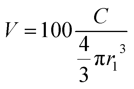 | (2) |
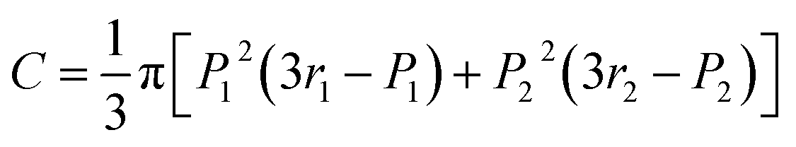 | (3) |
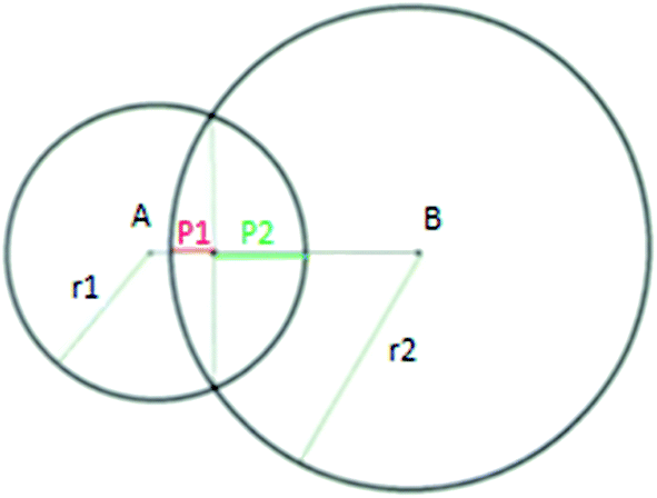 | ||
| Fig. 1 Calculation of overlapping area between two Hansen solubility spheres. | ||
Theoretically, V < 80% is necessary, but not sufficient, for the layering to occur.6,9,29 The HSP can also be used for the selection of solvents, as the solvents used for the formulation process have to dissolve both selected resins.5,6,34–36
The solubility parameters of the fluoropolymer and epoxy resins were determined in 54 solvents of known solubility at 20 °C at a concentration of 10% solids. The solutions were mixed for 24 hours and left to rest for extra 24 hours. Observations of solubility behavior were made 24 hours, 48 hours and 7 days after the dissolution of each resin in the considered solvents. HSPiP software, version 4.0.05 developed by Abbott and Yamamoto, was used for the calculation of the HSP parameters and of the overlap factor of the resins.
In the case of a thin film, it has been stated that the base coat component must spontaneously wet the substrate and that the total surface and interfacial surface tensions of the layer system must be as low as possible for the stratification to occur.7 Consequently, according to those theoretical considerations, the interfacial and surface tensions of the system have to follow three conditions (eqn (4–6)) for the selection of a suitable resin system:5
| γs − γs2 − γ12 − γ1 > 0 | (4) |
| γs1 − γs2 − γ12 ≥ 0 | (5) |
| γs1 − γ1 − γs2 + γ2 > 0 | (6) |
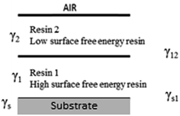 | ||
| Fig. 2 Interfacial and surface tensions in a two-component coating film. | ||
To calculate the interfacial tension between two materials 1 and 2, Wu established the following eqn (7).
 | (7) |
A GBX Digidrop goniometer was used for the calculation of the total surface tension γ, the dispersive (γd) and polar (γp) components following the previously described method of Wu.33 The contact angles formed with distilled water (γ = 72.8; γd = 21.8; γp = 51 mN m−1) and diiodomethane (γ = 50.8; γd = 50.8; γp = 0 mN m−1) (ASTM D 2578-67) at controlled temperature (25 °C) were determined.
2.4. Characterisations
The chemical composition was obtained by X-ray mappings at 13.0 kV, 25 μA. Detection of fluorine is quite difficult with X-ray analysis as the energy of fluorine (characteristic X-ray Kα = 0.677 keV) is very close to the one of carbon (Kα = 0.277 keV). As a consequence, chlorine was chosen to characteristic the fluoropolymer resin since it is also present in the fluoropolymer resin (the fluoro ethylene part contains a 3:1 fluorine/chlorine ratio).
Limiting oxygen index (LOI). The Limiting Oxygen Index (LOI) was measured using a Fire Testing Technology (FTT) instrument on specimens of 100 × 10 × 3 mm3 according to the standard “oxygen index” test (ISO 4589-2). This test allows measuring the minimum concentration of oxygen in a nitrogen/oxygen mixture required to just support combustion of a test sample under specified test conditions in a vertical position (the top of the test sample is ignited with a burner).
UL-94. UL-94 test is a vertical burning qualitative test and was performed according to IEC 60695-11-10 on 100 × 10 × 3 mm3 samples. It evaluates the tendency of a material to extinguish or to spread the flame after ignition of a material. Glowing and flaming combustion as well as dropping of flaming drops (with ignition of a cotton sample located under the barrel) are taken into account to classify the samples from V0 to non-classified (NC) where V0 is the best rating.
Mass loss calorimeter (MLC). A Fire Testing Technology (FTT) Mass Loss Calorimeter was used to perform measurements on samples following the procedure defined in ASTM E906. The equipment is identical to the one used in oxygen consumption cone calorimetry (ASTM E-1354-90), except that a thermopile in the chimney is used to obtain the heat release rate (HRR) rather than employing the oxygen consumption principle. Our procedure involved exposing specimens measuring 100 × 100 × 3 mm3 in horizontal orientation. Samples were wrapped in aluminum foil, exposing the upper surface to the conical heater. During the experiment carried out under a 50 kW m−2 heat flux corresponding to the common heat flux for a fully-developed fire (high external flux, large length scale, ambient temperature above auto-ignition temperature, low ventilation),38 the sample was placed on an insulating ceramic backing board at a distance of 35 mm from the heater.
The mass loss calorimeter is used to determine various fire retardant parameters including: heat release rate (HRR) as a function of time, time to ignition (TTI), time of flameout (TFO), total heat release (THR), peak of heat release rate (pHRR), mass loss rate (MLR) and specific mass loss rate (SMLR). The specific mass loss rate is calculated as the ratio between the MLR and the surface of the sample exposed to the MLC external irradiance level (i.e. 88.4 cm2 – ISO 5660 standard).39,40 In this study, the fire retardant parameters of coated polycarbonate were evaluated and compared to those of raw polycarbonate. Experiments were performed three times to ensure repeatability of results. The cone data reported in this article are an average of the three replicated experiments. The values were found to be reproducible within ±10% (relative standard deviation).
Temperature and UV ageing (UV). Accelerated ageing under UV-rays was performed by exposing the samples to both temperature and UV. Ageing was carried out in a weathering chamber from Q-lab (QUV/se: UV, condensation and control irradiance SOLAR EYE). The selected weathering conditions are derived from the ISO 4892-3 standard.41 The device is equipped with 8 UV lamps (UVA 340) with 0.89 W m−2 irradiance. Cycles of 4 hours under UV irradiation at 60 °C, followed by 4 hours dark at 50 °C were applied. The specimens (plates and barrels) were attached to the test panel and exposed to these consecutive cycles without interruption. Barrels were returned every week to ensure a uniform exposition on each side of the sample.
Temperature/relative humidity ageing (T/RH). Accelerated ageing T/RH were performed in a humidity chamber (HCP 108 supplied by Memmert). The temperature was kept constant at 60 °C while the humidity was set at 75% relative humidity.
Color change measurements. In order to evaluate the color change during ageing, L*a*b* measurements were performed on the plates before and after ageing. Color changes and reflectance were recorded using a Datacolor CHECK 3 portable spectrophotometer from Datacolor Industry. In the CIE (“Commission Internationale de l'Eclairage”, or International Commission on Illumination) L*a*b* system, L* represent the lightness of color (L* = 0 for the absolute black, L* = 100 for absolute white), the a* value indicates the color position between red and green (a* is green at one extremity (a* > 0) and red at the other (a* < 0)) and the b* value represents the color position on a yellow/blue scale (b* > 0 indicate blue and b* < 0 indicates yellow). a* and b* values are close to zero for neutral colors (white and gray) and increase in magnitude for more saturated or intense color (pure color). The difference of color between two samples (ΔE) can be calculated following eqn (10), with ΔL* representing the lightness difference and Δa* and Δb* the differences in a* and b* values respectively between the two samples.
 | (8) |
3. Results and discussion
3.1. Prediction of stratification
First, the Hansen solubility approach and the model based on surface and interfacial energies were applied to the selected systems to predict the stratification. One pure solvent and three solvent mixtures were selected: xylene, BuAc:xylene (1:1), MIBK:xylene (1:1) and MIBK:xylene:1-methoxy-2-propanol (50:30:20). The solubility of the epoxy and of the fluoropolymer resins were obtained experimentally following the Hansen approach to determine their degree of compatibility which permits the prediction of stratification. On the other hand, the surface and interfacial tensions were determined and the validity of the three conditions (eqn (5–7)) previously defined to obtain self-stratifying coating was verified.
| Resins | δd (J cm−3)1/2 | δp (J cm−3)1/2 | δh (J cm−3)1/2 | r |
|---|---|---|---|---|
| Epoxy | 19.55 | 19.40 | 4.33 | 19.90 |
| Fluoropolymer | 19.37 | 3.42 | 13.62 | 13.50 |
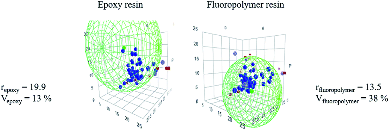 | ||
| Fig. 3 Hansen solubility spheres of epoxy and fluoropolymer resins, their radius r and overlap factor V (%). | ||
Theoretically, if both factors are below 80%, incompatibility is expected and thus self-stratification may occur.
From Fig. 3, as the radius of the solubility sphere of the fluoropolymer resin is lower than the one of the epoxy (13.5 compared to 19.9), it means that it has the lowest probability to interact with the other solubility sphere in the Hansen space. 38% represents the percentage by volume of the fluoropolymer resin solubility sphere that is occupied by the sphere of the epoxy resin, whereas only 13% of the epoxy sphere is occupied by the solubility sphere of the fluoropolymer resin. The overlapping area of the two solubility spheres C (calculated from eqn (3)) is equal to 42%, suggesting that the two polymers are theoretically incompatible. This result is in accordance with various studies based on blends of fluoropolymer (particularly Lumiflon LF200 grade) and different grades of epoxy resins (overlap factor below 80%).9
To conclude, the HSP of the epoxy and fluoropolymer resins meets the requirement for the stratification of the system.
The second approach to predict the self-stratification was then investigated. It is important to notice that the model based on the Hansen approach only considers the two selected polymers in its calculation, whereas the model based on surface and interfacial tensions takes into account the resins, the solvent or solvent blends, the substrate and also the curing agent in this case.
The three conditions for self-stratification (eqn (4–6)) of binary combinations were determined and the values are reported in Table 2. Results given in italics are not in accordance with the model.
| Conditions based on surface energy (mN m−1) | γs1 − γs2 − γ12 > 0 | γs1 − γ1 − γs2 + γ2 ≥ 0 | γs − γs2 − γ12 − γ1 > 0 |
|---|---|---|---|
| Xylene | 1.27 | 14.12 | 8.39 |
| BuAc:xylene (1:1) |
−0.06 | 0.40 | 10.58 |
| MIBK:xylene (1:1) |
1.35 | 36.35 | 9.24 |
| MIBK:xylene:1-methoxy-2-propanol (50:30:20) |
−0.52 | −3.72 | 4.04 |
According to the model, if xylene or a blend of MIBK:xylene (1:1) are used to formulate the coating, a self-stratified coating should be obtained. Two of three conditions (in bold) are satisfied for a blend of BuAc:xylene (1:1) whereas and only one condition is fulfilled for a blend of MIBK:xylene:1-methoxy-2-propanol (50:30:20). Thus, layering is predicted for the system in which xylene or a blend of MIBK:xylene are used. This is not the case for the other systems.
In order to confirm of not the prediction of both models, the coatings were then prepared and fully characterized.
3.2. Stratification of binary blends
Binary blends (epoxy and fluoropolymer resins) were formulated and applied on PC. Table 3 gathers the results obtained for the different coatings in terms of visual appearance, thickness, adhesion and stratification pattern (observed using SEM cross-sections).| Solvent | Appearance of the coating | Thickness (μm ± 5) | Cross hatch testing | Stratification pattern |
|---|---|---|---|---|
| Xylene | Rough, uniform, opaque | 60 | 5B | I |
| MIBK:xylene (1:1) |
Rough, uniform, opaque | 35 | 5B | I |
| BuAc:xylene (1:1) |
Rough, uniform, opaque, glossy | 65 | 5B | I |
| MIBK:xylene:1-methoxy-2-propanol (50:30:20) |
Uniform, glossy, opaque | 85 | 2B | I |
All unpigmented formulations lead to a type I stratification pattern (Table 3) but the visual appearance and the adhesion properties depend on the used solvent. With pure xylene and a MIBK:xylene blend, the coatings look similar (rough, uniform and opaque) and the best adhesion is obtained (5B). On the contrary, the use of BuAc:xylene and MIBK:xylene:1-methoxy-2-propanol solvent blends increases the gloss retention of the coating, even if adhesion properties are different: the best adhesion level is obtained with BuAc:xylene (5B), compared to a 2B rating obtained for the ternary solvent mixture.
Regarding the SEM micrographs, when a MIBK:xylene solvent blend is used, the stratification is clearly evidenced: two uniform layers are obtained, with a well-defined interlayer (Fig. 4a). Similar layering behaviors are obtained with the other solvent media (SEM micrographs are not presented). Then, to determine the composition of the two layers, EDX cross section mappings were carried out (Fig. 4b). According to those considerations, the chlorine X-ray mappings allow demonstrating that the upper layer is mostly composed of the fluoropolymer resin, and that the base layer, at the interface with the substrate, should be consequently mainly composed of the epoxy resin. The X-ray mappings are similar whatever the solvent used.
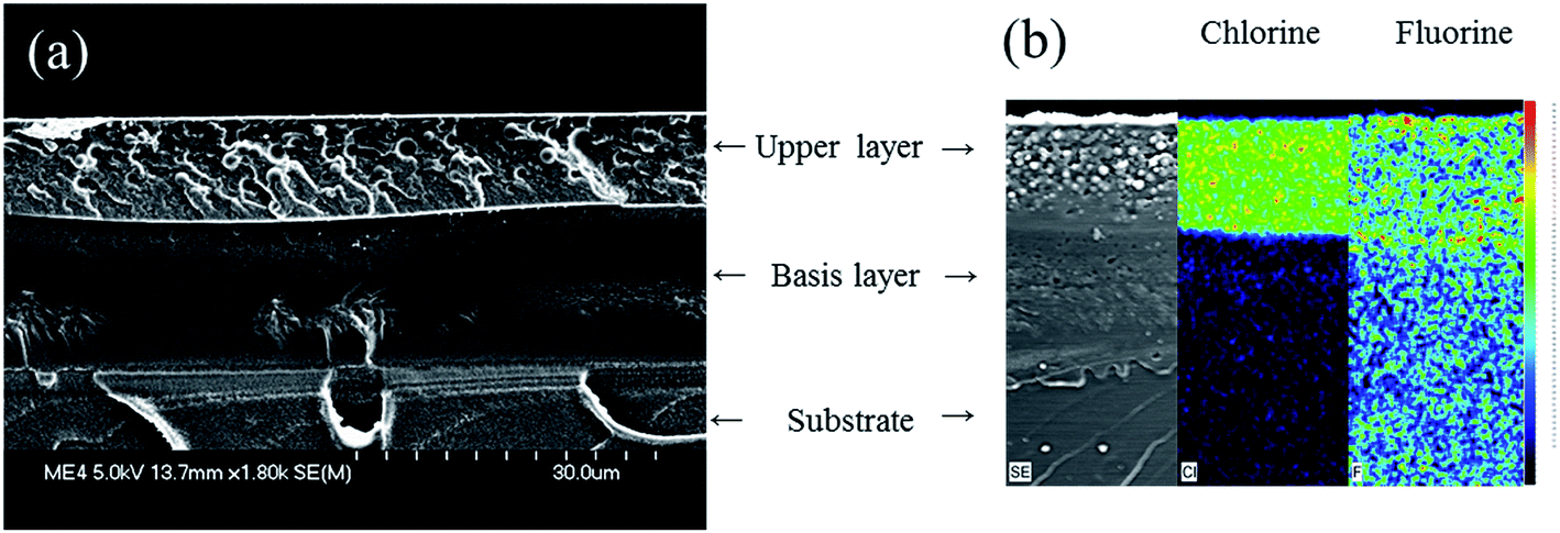 | ||
| Fig. 4 (a) SEM micrograph and (b) EDX X-ray mappings of chlorine and fluorine on a cross-section of an epoxy/fluoropolymer based coating prepared with in MIBK:xylene (1:1) as solvent. | ||
Thus, experimental characterizations revealed that, whatever the solvent used with the epoxy/fluoropolymer system, a type I stratification pattern is obtained. Visual appearance and adhesion are not really affected, except with the MIBK:xylene:1-methoxy-2-propanol solvent blend. These results allow making comparisons between the predictions given by the two theoretical models and the experimental results.
Contact angle measurements and infrared spectra of the resins (with and without solvents) and of the upper layer of the stratified films were also recorded to support the results (see ESI, Fig. S2 and Table S2†). However, neither the preparation of free standing films nor the delamination of the coatings from the PC were possible. Consequently, no comparison with the bottom layer of the film could be done. In addition, residual solvent was still remaining (>10 wt%) which makes the comparison of contact angle data not reliable enough to draw precise conclusions.
The Hansen approach, which predicted the incompatibility between the epoxy and fluoropolymer resins, is in accordance with the experimental observations. At the opposite, the model based on interfacial energy and surface tension predicted stratification for systems based on pure xylene and based on MIBK:xylene blend, which is in good agreement with experimental data. However, for the other solvent blends, even if the model do not predict the self-stratification, layering is observed experimentally. It can be noticed that the system for which two out of three conditions were not satisfied using this approach corresponds to the worst adhesion (2B) compared to the other systems (5B). Finally, for the BuAc:xylene solvent blend, the unsatisfied condition was very close to 0 and a great adhesion was obtained (5B).
The incorporation of filler in coating may affect the self-stratification. That is the reason why the next part of this study is dedicated to study the influence of the incorporation of red iron oxide on the stratification behavior.
3.3. Influence of Fe2O3 incorporation on stratification
According to the state of the art, in a self-stratifying coating, when fillers are dispersed in an epoxy medium, they remain in this phase during the formation of the film.9 The incorporation of red iron oxide in the epoxy/fluoropolymer systems previously described was thus considered. The pigment was first incorporated in the epoxy resin. SEM micrographs and EDX mappings are given in Fig. 5 and 6 respectively. Filler location, visual appearance of the solid films, thicknesses, adhesion rating and the resulting stratification patterns are detailed in Table 4.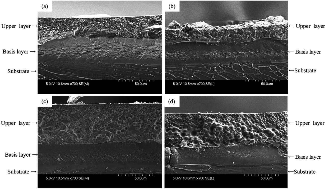 | ||
| Fig. 5 SEM micrographs of cross-sections of the epoxy/fluoropolymer based coating using (a) xylene, (b) BuAc:xylene (1:1), (c) MIBK:xylene (1:1), (d) MIBK:xylene:1-methoxy-2-propanol (50:30:20) as solvent. | ||
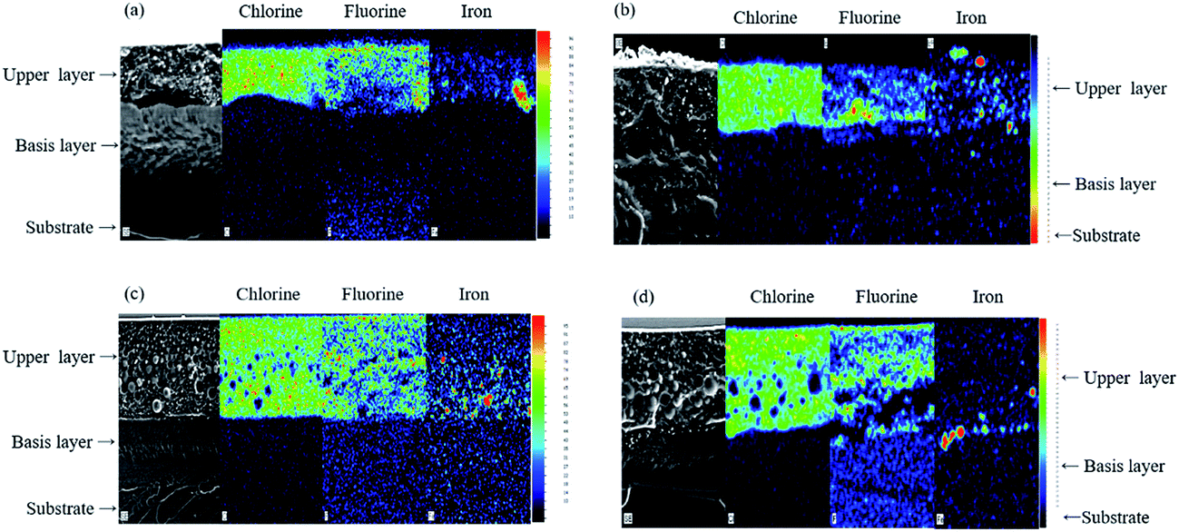 | ||
| Fig. 6 EDS X-ray mappings of chlorine, fluorine and iron on cross-sections of epoxy/fluoropolymer based coating in (a) xylene, (b) BuAc:xylene (1:1), (c) MIBK:xylene (1:1), (d) MIBK:xylene:1-methoxy-2-propanol (50:30:20). | ||
| Solvent | Pigment location after film formation | Appearance of the coating | Thickness (μm ± 5) | Cross hatch testing | Stratification pattern |
|---|---|---|---|---|---|
| Xylene | Fluoropolymer layer | Smooth, good pigment dispersion | 70 | 4B | I |
| MIBK:xylene (1:1) |
Fluoropolymer layer | Rough, medium pigment dispersion, small bubbles | 85 | 4B | I |
| BuAc:xylene (1:1) |
Fluoropolymer layer | Slightly rough, good pigment dispersion | 60 | 4B | I |
| MIBK:xylene:1-methoxy-2-propanol (50:30:20) |
Interphase epoxy/fluoropolymer layers | Rough, bad pigment dispersion | 75 | 1B | I |
The SEM micrographs and X-ray mappings of the cross-section confirm the self-stratification of the epoxy/fluoropolymer systems whatever the solvent or solvent blend used even when filler is added in the formulation. For all formulations, a type I stratification is obtained (Fig. 5a–d) and the fluoropolymer layer still appears to be the top layer, as it was already the case for unfilled formulations. Thus, in our study, iron oxide has no significant influence on the self-layering process. While it is clear that it does not impact the layering process, its affinity toward the resins and the dispersion quality however differ according to the selected solvent or solvent blend. Indeed, when xylene, blends of BuAc:xylene or MIBK:xylene are used, iron oxide is located in the fluoropolymer layer (Fig. 6a–c), even if it was initially dispersed in the epoxy medium. This means that, contrary to what is mentioned in the state of the art, iron oxide does not remain in its primary dispersion phase, but is located in the phase for which it has the highest affinity (here the fluoropolymer).
Considering the ternary blend (Fig. 5d and 6d), the filler is located at the interface between the two resins, pigments dispersion is not optimal and aggregates are noticeable. This result could be explained assuming that migration of red iron oxide during the film formation is not rapid enough compared to the fast evaporation rate of the solvent blend. In fact, according to the boiling temperature of the pure solvents, the MIBK:xylene:1-methoxy-2-propanol blend (respectively 116, 139 and 120 °C) has the lowest boiling temperature among the different solvents used. Since the solvent evaporates easily, the viscosity increases rapidly and the filler can not migrate in the upper phase. Moreover, the use of the ternary solvent blend leads to poor adhesion: 2B is obtained compared to 4B for the other formulations. The poor adhesion of the coating when such a blend of solvents is used was already observed for the unfilled system.
Considering the MIBK:xylene blend, which has the second lowest boiling temperature, even if iron oxide has migrated toward the fluoropolymer phase, the distribution is not homogeneous and aggregates are still observed in the lower part of the fluoropolymer phase (Fig. 6c). It means that the evaporation rate of the MIBK:xylene blend was not too high to prevent the migration of iron oxide in the fluoropolymer phase but was nonetheless too high to allow a good distribution in the whole layer. All these results prove that the choice of solvent is of primary importance: stratification is based on demixing, for which time and mobility are needed. Very high evaporation rates result in frustrated mixed coating and affect the quality of the resulting coating. A good compromise has to be found when selecting the solvent as it affects the formation of the film, the pigment dispersion and the adhesion properties.
To conclude about systems filled with red iron oxide, it was shown that this filler does not influence the layering behavior of the epoxy/fluoropolymer system, whatever the solvent used. However, adhesion properties, visual appearance of the film and filler dispersion are affected by the evaporation rate of the solvent or solvent blend. The coating designed with a blend of BuAc:xylene and/or with pure xylene combine the best adhesion and visual appearance.
In the following part, the unfilled and filled systems based on BuAc:xylene solvent blend were selected and applied on PC substrate to evaluate the flame retardant properties of the coated materials and compared to those of raw polycarbonate.
3.4. Flame retardant (FR) properties
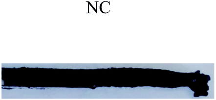
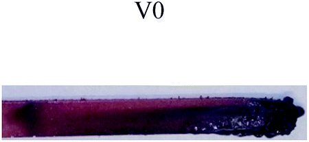
The FR properties of raw PC and PC coated with formulations containing or not red iron oxide were evaluated and compared. LOI, UL-94 and MLC tests were considered.| PC | Coated PC (no Fe2O3) | Coated PC (with Fe2O3) | |
|---|---|---|---|
| LOI (vol% O2) |  |
 |
 |
| UL-94 rating (3 mm thick samples) | 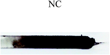 |
 |
 |
PC is a combustible self-charring polymer and thus reaches a quite high intrinsic LOI value (27 vol%) compared to other common thermoplastics.42 Dripping occurs during the test and is responsible for the value obtained: the fall of flaming drops leads to the self-extinction of the sample. For PC coated with the formulation without iron oxide, LOI value is slightly decreased compared to pure PC (25 vol% versus 27 vol% respectively). In that case, the dripping is more pronounced compared to the raw PC, as both the coating and the PC burn. Although the charring behavior is much more important when the coating is present, it does not prevent the flaming and dripping. In addition, the ignition of the coated sample is quicker, as the coating probably ignites earlier than the PC.
On the contrary, an increase in the LOI value from 25 to 32 vol% is observed when iron oxide is incorporated into the coating. A visual change in the fire behavior of coated PC is also noticeable, and no dripping is observed with the filled formulation. Ignition of the sample also takes more time. The UL-94 test confirms the tendency observed with LOI: whereas PC and coated PC (without Fe2O3) are non-classified (NC) and drip, samples containing iron oxide lead to improved flame retardant properties (Table 5). V0 rating is achieved and no dripping is observed: self-extinguishment occurs less than 6 seconds after ignition. The resulting char is mainly formed at the beginning of the test during the application of the flame. The presence of iron oxide prevents the flame propagation and the dripping during the test, thus enhancing the flame retardant properties of polycarbonate. From the most relevant papers, it is established that metal oxide particles promote the formation of a crosslinked network in the solid phase, particularly when combined with phosphorus compound,43 that may prevent the release of small molecules such as volatiles (thermal barrier effect). In particular, iron containing compounds may have a catalytic action, acting as synergists and smoke suppressants in some thermoplastic polymer formulations.17,44
To try to evidence the catalytic effect of iron oxide, thermogravimetric analyses (TGA) and difference weight loss calculations were performed on the dried fluoropolymer containing or not iron oxide (see ESI, Table S3 and Fig. S4†). It was shown that iron oxide catalyzes the thermal degradation of the fluoropolymer resin during combustion. The mechanism of action may be similar to that reported for ethylene tetrafluoroethylene, with which it was already demonstrated that iron and transition metal salts can accelerate the degradation of such polymer through dehydrofluorination and oligomers formation.45 The dehydrofluorination catalysts promote double bonds aromatic formation that may undergo crosslinking and accelerate the formation of char.
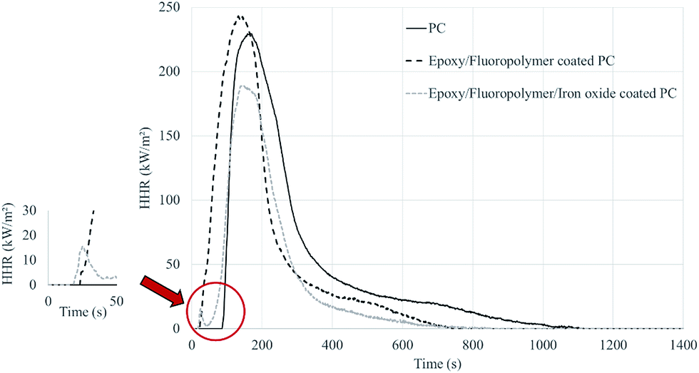 | ||
| Fig. 7 HRR curves obtained for PC and coated PC with unfilled and filled formulations. | ||
| PC | Coated PC (no Fe2O3) | Coated PC (with Fe2O3) | |
|---|---|---|---|
| a Percentage are calculated according the difference with the virgin PC. | |||
| Time to ignition (s) | 92 ± 6 | 26 ± 2 | 20 ± 3 |
| pHRR (kW m−2) | 231 ± 6 | 250 ± 2 (+8%)a | 191 ± 23 (−17%) |
| THR (MJ m−2) | 52 ± 1 | 46 ± 3 (−12%) | 29 ± 4 (−44%) |
| TFO (s) | 1077 ± 47 | 735 ± 30 | 735 ± 67 |
| SMLR (g m−2 s−1) | 3.1 ± 0.1 | 4.8 ± 0.3 | 4.1 ± 0.1 |
PC is a char forming polymer. After ignition, it melts and forms a char which swells until it reaches a height of about eight centimeters. Char then degrades and only ashes remain at the end of the test.
The behavior of coated PC is different, whatever the coated formulation. Before ignition, PC swells under the coating, which gradually delaminates from the corners of the plate (see ESI, Fig. S3,† the black upper part represents the burned coating after cone testing whereas the melt structure underneath corresponds to the substrate). Despite the coating, PC chars and sometimes causes the coating to almost touch the spark plug before the ignition takes place.
For coated PC samples without Fe2O3. For coated PC samples without Fe2O3, a slight increase of the pHRR (+8%) is observed compared to pure PC. Moreover, the TTI is reduced (26 s with the coated PC compared to 92 s with uncoated PC) (Table 6). One hypothesis is that the coating is less thermally stable than the PC under radiative heat flux. Indeed, it was already reported that shorter TTI can be due to a reduction in the thermal stability: since ignition is controlled by the supply of fuel gases, less thermally stable specimens tend to ignite earlier. In our case, the epoxy/fluoropolymer protective layer would thus be less thermally stable than the PC itself. To validate this statement, thermogravimetric analyses were performed on PC and on the dried fluoropolymer coating to compare their thermal stability (see ESI, Table S4 and Fig. S5†). Results show that the fluoropolymer coating is less thermally stable (onset temperature of degradation of 235 °C compare to 420 °C for PC) under pyrolytic conditions.
When iron oxide particles are incorporated into the coating. When iron oxide particles are incorporated into the coating, an improvement in the fire behavior is noticeable: a decrease of both pHRR (−17%) and THR (−44%) compared to pure PC is observed. The ignition of the samples occurs in the corners, i.e. in the area where the coating has delaminated, whereas ignition usually occurs in the center of the sample for specimens without fillers. In addition, the effect of iron oxide is well noticeable by the shoulder which appears after the ignition of the coating (between 20 and 50 seconds, Fig. 7): the flame have difficulties in persisting compared to the epoxy/fluoropolymer coating with which the HRR raises directly after the ignition. This again suggests that the coating that includes Fe2O3 is a good fire barrier, which confirms the observations made during UL-94 and LOI testing.
3.5. Weathering testing and FR properties after accelerated ageing
When designing coating to flame retard polymer, one important issue is the ageing of such coating. That is the reason why it will be investigated in the last part of this paper. The effects of the temperature, relative humidity and UV radiation on raw and coated PC and on their FR properties will be detailed.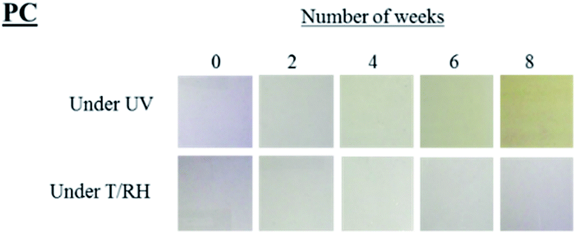 | ||
| Fig. 8 Visual appearance of the PC plates after UV and T/RH exposure. | ||
| Polycarbonate | |||||
|---|---|---|---|---|---|
| Under UV | |||||
| Time (week) | 0 | 2 | 4 | 6 | 8 |
| L* | 87.5 | 87.4 | 87.7 | 85.0 | 87.8 |
| a* | −0.8 | −0.7 | −1.4 | −2.2 | −2.7 |
| b* | −2.8 | −1.3 | 2.2 | 8.1 | 11.9 |
| ΔE* | — | 1.6 | 5.1 | 11.3 | 15.1 |
| UL-94 | NC | NC | NC | NC | NC |
| LOI (vol%) | 28 | 28 | 27 | 26 | 25 |
|
|||||
| Under T/RH | |||||
| Time (week) | 0 | 2 | 4 | 6 | 8 |
| L* | 87.5 | 87.3 | 87.8 | 87.6 | 87.8 |
| a* | −0.8 | −0.0 | −0.1 | −0.1 | −0.1 |
| b* | −2.8 | −3.8 | −4.0 | −3.8 | −3.9 |
| ΔE* | — | 1.3 | 1.4 | 1.2 | 1.4 |
| UL-94 | NC | NC | NC | NC | NC |
| LOI (vol%) | 28 | 28 | 27 | 26 | 26 |
Without filler. The coated PC with the epoxy/fluoropolymer self-stratified system leads to very promising results after 8 weeks of exposure under T/RH conditions: color changes are negligible (ΔE* < 5.7) and no change in the visual appearance (blistering, cracks…) occurs (Fig. 9, Table 8). Under UV conditions however, changes occur at a fast rate: yellowing is noticed even after 2 weeks of exposure (b* raised from 0.0 to 18.6) but remains constant after that time (19.4 < ΔE* < 23.0). The comparison with the data of raw PC shows that yellowing is even more pronounced when the coating is applied. This yellowing could be reasonably attributed to the epoxy resin which is well known for having poor resistance to UV.51 Indeed, a few hours under UV exposure cause its chalking and yellowing due to photo-degradation (similar to that of PC). Moreover, no blistering nor removal of paint are noticed during the test: the best rating (5B) is still obtained after 8 weeks of weathering. Finally, no change in the fire retardant properties at LOI and UL94 tests compared to the non-aged samples are registered whatever the weathering conditions.
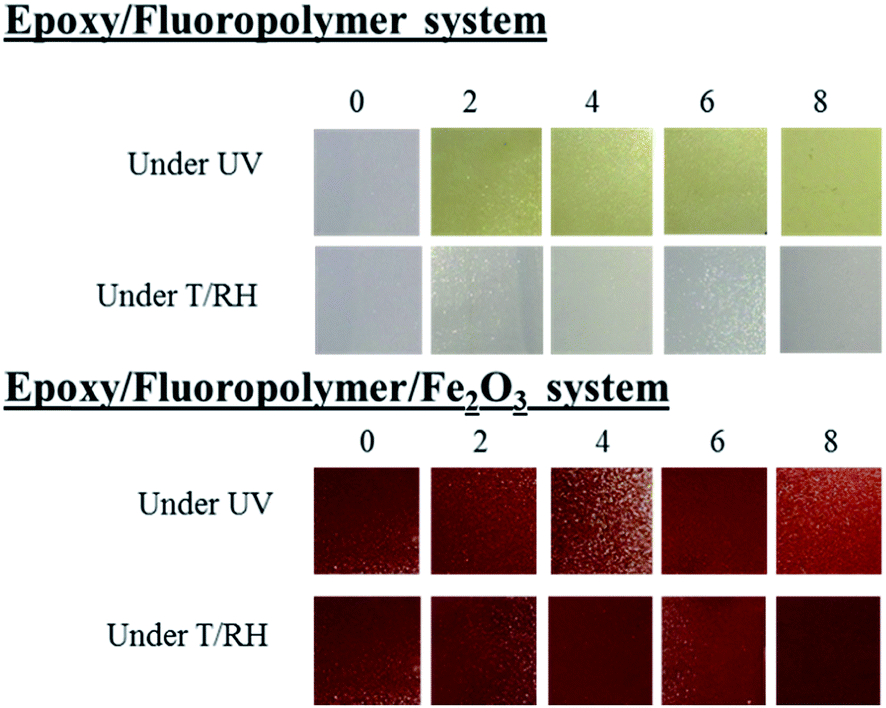 | ||
| Fig. 9 Visual appearance of the plates after UV and T/RH exposure. | ||
| Coated PC with epoxy/fluoropolymer system | |||||
|---|---|---|---|---|---|
| Under UV | |||||
| Time (week) | 0 | 2 | 4 | 6 | 8 |
| L* | 70.2 | 75.6 | 71.0 | 79.0 | 82.4 |
| a* | −1.0 | −0.8 | −0.4 | −1.2 | −2.2 |
| b* | 0.0 | 18.6 | 20.7 | 17.6 | 19.4 |
| ΔE* | — | 19.4 | 20.8 | 19.7 | 23.0 |
| UL-94 | NC | ||||
| LOI (vol%) | 25 | ||||
| Adhesion | 5B | ||||
|
|||||
| Under T/RH | |||||
| Time (week) | 0 | 2 | 4 | 6 | 8 |
| L* | 70.2 | 72.0 | 74.8 | 69.6 | 73.9 |
| a* | −1.0 | 0.7 | 0.9 | 0.0 | 0.7 |
| b* | 0.0 | 1.7 | 2.6 | 0.7 | 2.8 |
| ΔE* | — | 3.0 | 5.6 | 1.3 | 4.9 |
| UL-94 | NC | ||||
| LOI (vol%) | 25 | ||||
| Adhesion | 5B | ||||
| Coated PC with epoxy/fluoropolymer/Fe2O3 system | |||||
|---|---|---|---|---|---|
| Under UV | |||||
| Time (week) | 0 | 2 | 4 | 6 | 8 |
| L* | 37.9 | 39.5 | 38.2 | 38.7 | 38.4 |
| a* | 28.1 | 29.8 | 29.1 | 30.4 | 30.2 |
| b* | 19.3 | 23.4 | 22.3 | 23.4 | 23.5 |
| ΔE* | — | 4.8 | 3.2 | 4.8 | 4.7 |
| UL-94 | V0 | ||||
| LOI (vol%) | 32 | ||||
| Adhesion | 4B | ||||
|
|||||
| Under T/RH | |||||
| Time (week) | 0 | 2 | 4 | 6 | 8 |
| L* | 37.9 | 39.8 | 41.4 | 40.7 | 40.7 |
| a* | 28.1 | 28.8 | 31.1 | 30.1 | 30.7 |
| b* | 19.3 | 21.1 | 24.3 | 22.9 | 23.7 |
| ΔE* | — | 2.7 | 6.8 | 5.0 | 5.8 |
| UL-94 | V0 | ||||
| LOI (vol%) | 32 | ||||
| Adhesion | 4B | ||||
With Fe2O3. Under both T/RH and T/UV exposure, no change in the visual appearance of the coating nor by returning the back of the plate is noticed, and the adhesion rating (4B) remains constant. The incorporation of iron oxide allows avoiding the yellowing of the coating (Δb* < 5 and ΔE* < 4.8, Fig. 9, Table 8) and prevents the UV rays from reaching the substrate (no yellowing of the back of the plate is noticeable). By the fire performances are also maintained: both the LOI value and the UL-94 classification are comparable (32 vol% and V0 rating) whatever the weathering conditions and exposure time.
To conclude, T/RH weathering tests on the coated PC are very conclusive: no influence is registered after 8 weeks of exposure, and the coating prevents the decrease of the fire performances of the PC itself. No modification in the adhesion nor in the quality of the films is observed both under T/RH and UV. Under UV, the coating also allows maintaining the initial properties of the specimens. However, the unfilled coating does not prevent from the penetration of UV which is responsible for the yellowing of the substrate. Finally, the epoxy resin, also prone to the yellowing under UV radiation, causes the increase of the yellowing of the whole coated system. The incorporation of iron oxide into the coating allows overcoming this issue by creating a barrier to the UV both for the epoxy part of the coating and for the substrate.
4. Conclusion
This paper reports an innovative approach to fire retard polycarbonate, by producing unpigmented and pigmented laminated epoxy/fluoropolymer coatings. The top layer of the one pot coating was found to be composed of the fluoropolymer resin, and the base layer of the crosslinked epoxy resin. The solvents have proven to hugely affect the quality of the resulting film, and have to be chosen very carefully. Indeed, they can impact both adhesion properties and pigment dispersion thus visual appearance of the coating in a negative manner.Incorporation of red iron oxide in the epoxy phase has no negative effect on the layering behavior. Moreover, we have shown that the filler has a higher affinity with the fluoropolymer resin, and thus does not remain in the phase where it was initially dispersed (i.e. the epoxy resin). It was also shown that the evaporation rate of solvents influences the migration of fillers toward the fluoropolymer medium. When a blend of MIBK:xylene:1-methoxy-2-propanol (50:30:20) is used, fillers have not enough time to migrate toward the topcoat layer and are thus trapped at the interface between the two resins. This poor pigment dispersion is detrimental to the film aspect and to the adhesion properties.
On the other hand, the incorporation of a low amount (10 wt%) of iron oxide particles in the coating leads to an outstanding improvement of the fire performances when such coating is applied on PC. A 32 vol% LOI value and a V0 ranking at the UL-94 test were achieved for the pigmented system. Moreover, the filled coating exhibits good fire performances at MLC: 17% and 44% decrease compared to pure PC in terms of pHRR and THR respectively. Iron oxide was already reported to catalyze the thermal degradation of fluoropolymer resins during combustion, probably through the formation of aromatic double bonds that may undergo crosslinking and accelerate the formation of char. This char formation mainly prevent from the dripping and the propagation of the flame by forming a protective barrier. However further characterizations are required to fully understand the mode of action of the iron oxide in the self-stratified composition. Finally, a great stability over ageing under T/RH is obtained when both the unfilled and filled coatings are applied on PC. Under UV, the yellowing of the non-pigmented coated PC is however accelerated but the filled coating protects the underneath substrate from UV rays attack.
To conclude, the use of metal oxide as only and sufficient flame retardant is a very specific exception. Bulk flame retarded PC is not expected to be replaced by coated PC. However, this novel approach represents a proof of concept to flame retard durably polycarbonate in a cheap and fast manner, simultaneously maintaining the mechanical properties of PC. Efforts have now to be put on the development of transparent self-stratifying coatings with similar flame retardant as well as weathering resistant properties.
Conflicts of interest
There are no conflicts to declare.Acknowledgements
The authors would like to acknowledge the ANR (Agence Nationale de la Recherche) for funding the STIC project (ANR-14-CE27-0010). We are also thankful to the MATIKEM competitiveness cluster for supporting the project and to Dr Ahmed Addad for skillful assistance and discussion in microscopic field.References
- M. Le Bras, S. Bourbigot, R. Delobel and L. N. Gordon, Fire Retardancy of Polymers – The Use of Intumescence, The Royal Society of Chemistry, Cambridge, UK, 1998 Search PubMed.
- M. Jimenez, S. Duquesne and S. Bourbigot, Polym. Adv. Technol., 2012, 23, 130–135 CrossRef CAS.
- S. Duquesne, M. Jimenez and S. Bourbigot, J. Appl. Polym. Sci., 2014, 131, 39566 CrossRef.
- V. V. Verkholantsev, Prog. Org. Coat., 1985, 13, 71–96 CrossRef CAS.
- A. Toussaint, Prog. Org. Coat., 1996, 28, 183–195 CrossRef CAS.
- P. Vink and T. L. Bots, Prog. Org. Coat., 1996, 28, 173–181 CrossRef CAS.
- C. Carr and E. Wallstöm, Prog. Org. Coat., 1996, 28, 161–171 CrossRef CAS.
- E. Langer, H. Kuczyńska, E. Kamińska-Tarnawska and J. Łukaszczyk, Prog. Org. Coat., 2011, 71, 162–166 CrossRef CAS.
- S. Benjamin, C. Carr and D. J. Walbridge, Prog. Org. Coat., 1996, 28, 197–207 CrossRef CAS.
- R. Berkau, M. Gailberger, T. Gruber, K. Holdik, G. Meichsner and F. Mezger, US Pat., 7186772 B2, 2007.
- V. V. Verkholantsev, Eur. Coat. J., 2005, 20 CAS.
- M. McHenry and D. Laughlin, Acta Mater., 2000, 48, 223–238 CrossRef CAS.
- B. Pan, H. Qiu, B. Pan, G. Nie, L. Xiao, L. Lv, W. Zhang, Q. Zhang and S. Zheng, Water Res., 2010, 44, 815–824 CrossRef CAS PubMed.
- P. Carty, E. Metcalfe and S. White, Polymer, 1992, 33, 2704–2708 CrossRef CAS.
- G. A. Olah, Freidel Crafts and Related Reactions, Wiley, New York, NY, 1963 Search PubMed.
- H. Marsh, D. Crawford and D. W. Taylor, Carbon, 1983, 21, 81–87 CrossRef CAS.
- E. Gallo, U. Braun, B. Schartel, P. Russo and D. Acierno, Polym. Degrad. Stab., 2009, 94, 1245–1253 CrossRef CAS.
- R. L. Markezich, in Plastics Additives: An A–Z reference, ed. G. Pritchard, Springer Netherlands, Dordrecht, 1998, pp. 327–338 Search PubMed.
- P. Carty and B. M. Adger, Appl. Organomet. Chem., 1990, 4, 127–131 CrossRef CAS.
- P. Carty, E. Metcalfe and T. J. Saben, Fire Saf. J., 1991, 17, 45–56 CrossRef CAS.
- W. P. Whelan, J. Fire Retard. Chem., 1979, 6, 206–219 CAS.
- E. D. Weil and N. G. Patel, Polym. Degrad. Stab., 2003, 82, 291–296 CrossRef CAS.
- A. Laachachi, M. Cochez, M. Ferriol, J. M. Lopez-Cuesta and E. Leroy, Mater. Lett., 2005, 59, 36–39 CrossRef CAS.
- S. Krishnan, R. L. Price and R. J. White, US Pat., 4650823 A, 1987.
- K. J. Nangrani, R. Wenger and P. G. Daugherty, Plast. Compd., 1988, 11, 27–31 CAS.
- M. M. Hirschler, Polymer, 1984, 25, 405–411 CrossRef CAS.
- L. Truffault, Synthèse et caractérisation de nanoparticules à base d’oxydes de cérium et de fer pour la filtration des UV dans les produits solaires, University of Orléans, 2010 Search PubMed.
- P. Xu, G. M. Zeng, D. L. Huang, C. L. Feng, S. Hu, M. H. Zhao, C. Lai, Z. Wei, C. Huang, G. X. Xie and Z. F. Liu, Sci. Total Environ., 2012, 424, 1–10 CrossRef CAS PubMed.
- C. M. Hansen, The 3D solubility parameter and solvent diffusion coefficient, Aarhuus Stiftsbogtrykkerie A/S, Copenhagen, 1967 Search PubMed.
- A. Beaugendre, S. Degoutin, S. Bellayer, C. Pierlot, S. Duquesne, M. Casetta and M. Jimenez, Prog. Org. Coat., 2017, 103, 101–110 CrossRef CAS.
- V. V. Verkholantsev and M. Flavian, Prog. Org. Coat., 1996, 29, 239–246 CrossRef CAS.
- D. J. Walbridge, Prog. Org. Coat., 1996, 28, 155–159 CrossRef CAS.
- V. V. Verkholantsev, Prog. Org. Coat., 1995, 26, 31–52 CrossRef CAS.
- I. Hopkinson and M. Myatt, Macromolecules, 2002, 35, 5153–5160 CrossRef CAS.
- E. Langer, H. Kuczyńska, E. Kamińska-Tarnawska, J. Łukaszczyk and G. Kamińska-Bach, Prog. Org. Coat., 2009, 66, 228–234 CrossRef CAS.
- A. Abbasian, S. R. Ghaffarian and N. Mohammadi, Iran. Polym. J., 2004, 13, 61–68 CAS.
- W. Funke, J. Oil Colour Chem. Assoc., 1976, 59, 398–403 CAS.
- B. Schartel and T. R. Hull, Fire Mater., 2007, 31, 327–354 CrossRef CAS.
- J. Luche, T. Rogaume, F. Richard and E. Guillaume, Fire Saf. J., 2011, 46, 451–461 CrossRef CAS.
- ISO 5 660, Reaction to fire tests – heat release, smoke production and mass loss rate – Part 1, 2002 Search PubMed.
- ISO 4892-3, Methods of exposure to laboratory sources – Part 3: Fluorescent UV lamps, 2013 Search PubMed.
- SpecialChem SA, Fire Resistance (LOI), http://omnexus.specialchem.com/polymer-properties/properties/fire-resistance-loi, 2017, accessed 3 March2007.
- E. Gallo, B. Schartel, D. Acierno and P. Russo, Eur. Polym. J., 2011, 47, 1390–1401 CrossRef CAS.
- P. Carty and S. White, Fire Mater., 1994, 18, 151–166 CrossRef CAS.
- J. G. Drobny, Technology of fluoropolymers, CRC Press, Boca Raton, FL, USA, 2nd edn, 2008 Search PubMed.
- C. E. Hoyle, H. Sha and G. L. Nelson, J. Polym. Sci., Part A: Polym. Chem., 1992, 30, 1525–1533 CrossRef CAS.
- N. Nagai, H. Okumura, T. Imai and I. Nishiyama, Polym. Degrad. Stab., 2003, 81, 491–496 CrossRef CAS.
- A. L. Anrady, N. D. Searle and L. F. E. Crewdson, Polym. Degrad. Stab., 1992, 35, 237–247 Search PubMed.
- M. Diepens and P. Gijsman, Polym. Degrad. Stab., 2009, 94, 34–38 CrossRef CAS.
- A. Rivaton, Polym. Degrad. Stab., 1995, 49, 163–179 CrossRef CAS.
- N. Rajagopalan and A. S. Khanna, Int. J. Sci. Res. Pub., 2013, 3, 1–4 Search PubMed.
Footnote |
| † Electronic supplementary information (ESI) available. See DOI: 10.1039/c7ra08028j |
| This journal is © The Royal Society of Chemistry 2017 |