 Open Access Article
Facet-dependent magnesiation behavior of α-Sn as an anode for magnesium ion batteries
Wei Jin and
Zhiguo Wang *
*
School of Physical Electronics, Center for Public Security Technology Research, University of Electronic Science and Technology of China, Chengdu, 610054, P. R. China. E-mail: zgwang@uestc.edu.cn
First published on 15th September 2017
Abstract
The adsorption and magnesiation behavior of Mg onto α-Sn and Mg2Sn through (100), (110) and (111) surfaces were investigated by using first-principles calculations. It was found that the Mg atom prefers to be adsorbed on the surface rather than diffuse into the sub-surface of Sn. The diffusion energy barrier is higher for Mg diffusing from the surface to the subsurface compared with the internal diffusion. Mg diffuses much faster along the <100> direction than along the <110> and <111> directions. The diffusion process from the surface to the subsurface is a rate-limiting step for Mg intercalation into Sn. The surface magnesiation is also a rate-limiting step for Mg intercalation into Mg2Sn though (100) and (110) surfaces, whereas the surface magnesiation of the Mg2Sn (111) surface is easier than the (100) and (110) surfaces. Surface modification is necessary to improve the magnesiation behavior of Sn as an anode for MIBs, especially when the anode materials are reduced to the nanoscale.
1. Introduction
Magnesium ion batteries (MIBs) have attracted much attention in recent years1–7 due to their advantages compared with current commercial lithium ion batteries, such as high safety, high specific capacity, and low price. To further improve the overall battery performance of MIBs, a variety of materials have been studied to be used as anodes and cathodes for MIBs.8–10 Because of the incompatibility between Mg metal and conventional electrolyte, the development of the anode materials is slower than that of the cathode materials.11 Among all the anode candidates, tin (Sn)12,13 has been regarded as a promising anode for MIBs owing to its high capacity and compatibility with the conventional electrolyte. It was found that the Sn can endure much higher strain and capacity retention by reducing their size to nanoscale.14,15 Many studies had been focus on the understanding of Mg diffusion process within the Sn anodes.13,16 However, Mg ions transport in the Sn surface exposed to the electrolyte is of great importance as the first step of the Mg insertion into the anode. The surface magnesiation can hardly be observed by an experimental setup; density functional theory (DFT) calculations can provide an atomistic understanding of the magnesiation procedure and predict the electrochemical properties of surface magnesiation.17,18 Kaghazchi et al.18 have studied the lithiation of Li into Sn(100) surface and found that Li was more stable at interstitial sites between the topmost surface-layers of Sn(100) than at the surface sites and bulk sites using DFT. Jung et al.19 investigated the intercalation of a Li atom into the surface and subsurface layers of Ge and Sn using DFT calculations. Their simulation results suggested that the rate-limiting step in Sn was the subsurface diffusion in both the Sn(100) and Sn(111) surfaces. They also found that Li diffused faster by at least two orders of magnitude along the [100] crystal orientation than along the [111] crystal orientation.17Although Sn has been studied as anode for MIBs,12,13 yet few studies have been performed on Mg magnesiation into Sn surfaces. As the surface lithiation is the rate-limiting step when Sn used as anode for lithium ion batteries, in this work we studied Mg magnesiation into Sn(100), Sn(110), Sn(111), Mg2Sn(100), Mg2Sn(110), and Mg2Sn(111) surfaces using DFT calculations to understand the electrochemical behavior of the Sn as the anode materials for the MIBs.
2. Computational methods
All the calculations were carried out using the DFT as implemented within the SIESTA code.20 The generalized gradient approximation (GGA) with Perdew–Burke–Ernzerhof (PBE) function was used to describe the electron exchange–correlation term.21,22 The interactions between the core and valence electrons were described by nonlocal norm-conserving pseudo-potentials.23 The valence electron wave functions were expanded using double-ζ basis functions. For calculating the self-consistent Hamiltonian matrix elements, the charge density was projected on a real space grid with a cutoff of 150 Ry. The calculated bulk bond length of Sn–Sn was 2.89 Å for α-Sn, which was in good agreement with experimental value of 2.81 Å (ref. 24) and previous DFT calculated value of 2.88 Å.19The surfaces of α-Sn were modeled using asymmetric slabs which composed of fourteen layers Sn atoms. One side of the slabs was saturated with hydrogen atoms. The bottom four Sn atomic layers and the hydrogen layer were fixed to model the bulk Sn, and the remaining layers and the adsorbed Mg atom were allowed to relax freely. The slab thickness are 22.4, 31.8, and 25.5 Å for slabs with (100), (110) and (111) surfaces, respectively, which has been previously tested to be reliable25 for investigating adsorption and diffusion for Li in Sn,18,19 Ge19 and Si17,26 surfaces. The surfaces of the Mg2Sn were modeled with slab thickness of 22.8, 32.3, and 25.3 Å for (100), (110) and (111) facets, respectively. The use of such asymmetric slabs was corrected by the dipole correction scheme of Neugebauer and Scheffler.27 A vacuum spacing between the slabs and its image exceeds 20 Å to avoid the periodic image interactions.
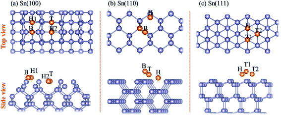
Because the unreconstructed Sn(100)-(1 × 1) surface has been proved to be unstable,18 we used the (4 × 2) surface unit cell to simulate the Sn(100) surface which is the ground state of Sn(100) consisting of buckled rows of Sn dimers, as shown in Fig. 1a. The relaxed Sn(110) and Sn(111) surfaces were shown in Fig. 1b and c, respectively. The adsorption energy (Ead) of Mg on Sn surfaces was calculated using eqn (1):
 | (1) |
3. Results and discussion
3.1 Adsorption and magnesiation Mg into Sn(100) surface
There are four possible adsorption sites for Mg on Sn(100)-c (4 × 2) surface due to the symmetry of the geometric structure, shown in Fig. 1a. The H1 is the pedestal site, and B is the dimer bridge site. The cave (H2) site is located at the bottom of the trough and the valley bridge (T) site is on top of the third-layer Sn atom.28 According to the definition of adsorption energy in eqn (1), a negative value means a favorable exothermic reaction between the substrate and Mg. The larger the negative value is, the more favorable of the reactions is. The calculated adsorption energies are listed in Table 1. Among all the adsorption sites, the H2 site is with the largest negative values, which means that the Mg prefers to be adsorbed at the H2 site. The H1 site is less stable than H2 site by 0.15 eV. The geometry optimizations for Mg adsorption starting from the B site eventually led to the stable H1 site. Besides, the T site is with adsorption energy of −0.53 eV, which is less stable adsorption site for Mg.| Sn(100) | Sn(110) | Sn(111) | |||
|---|---|---|---|---|---|
| Adsorption site | Ead/eV | Adsorption site | Ead/eV | Adsorption site | Ead/eV |
| H1 | −1.20 | H | −4.39 | H | −1.62 |
| H2 | −1.35 | B | −1.39 | T1 | −0.81 |
| B | −1.20 | T | −1.39 | T2 | −1.46 |
| T | −0.53 | ||||
The energetically favorable adsorption site, H2, on Sn(100) was taken to be the initial site for the magnesiation of Mg into the Sn crystal through Sn(100) surface. Based on the adsorption energies listed in Table 1, the diffusion pathway H2 → S1 → S2 → S3 → S4 → S5 was investigated, which is the energetic favorable diffusion pathway for Mg magnesiation into Sn through (100) surface. A similar diffusion behavior was found for the lithiation of Si(100),17,26 Sn(100)18 and Ge (100)19 surfaces. We used Sn (n = 1, 2, 3, 4, 5) to represent the adsorption sites of Mg at the nth layer of Sn away from the surface. As shown in Fig. 2, the Mg atom is energetically favorable at the tetrahedral site with the four nearest Sn atoms. Mg diffuses from on stable tetrahedral site to a nearest one by passing through a hexagonal site. The diffusion energy profile of Mg through the pathway H2 → S1 → S2 → S3 → S4 → S5 was shown in Fig. 2. The energy for Mg at the H2 and Sn site increases as the Mg magnesiation into the inside of Sn. The closer the adsorbed site to the Sn(100) surface, the lower the energy is, which is due to more effective stress release near the surface.29 The diffusion energy barriers for Mg magnesiation into Sn through the (100) surface can be read from Fig. 2. The diffusion energy barrier is 1.05 eV for Mg diffuses from H2 to S1 site, and which are 0.84, 0.66, 0.65 and 0.63 eV for Mg diffuses to S2, S3, S4 and S5, respectively. It is can be seen that the surface magnesiation of Mg is with the highest diffusion energy barrier, whereas the inside diffusion with small one, which also shows less dependence on the position. So the surface magnesiation (H2 → S1) becomes the rate-limiting step during Mg intercalated into Sn through the (100) surface.
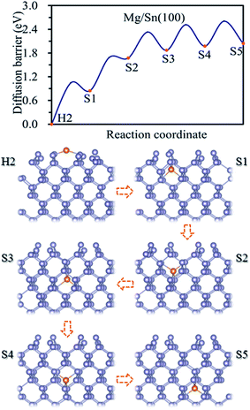 | ||
| Fig. 2 Diffusion energy profile for Mg magnesiation into the surface and subsurface sites of Sn(100) and the atomic geometries at local minimum points in the profile. | ||
3.2 Adsorption and magnesiation Mg into Sn(110) surface
Three adsorption sites, i.e. H, B and T sites were considered for the adsorption of Mg on Sn(110) surface, as shown in Fig. 1b. The H site is above the center of triangle structure composed of three Sn atoms on the surface, B site is on top of a Sn–Sn bond, and T site is above the top of one Sn atom. The calculated adsorption energies were listed in Table 1. The H site is the energetically stable one with an adsorption energy of −4.39 eV. It was found that the T site is not stable for Mg adsorption, and the Mg atom moves from the T site to the adjacent H site after relaxation. The adsorption energy is −1.39 eV for the Mg adsorbed at B site, which is the metastable adsorption site.The magnesiation of Mg into Sn through (110) surface were studied by investigating the diffusion of Mg along H → S1 → S2 → S3 → S4 → S5 diffusion path. The energetically stable sites for the intercalated Mg atom are the interstitial tetrahedral sites. The diffusion of Mg inside the Sn is through jumping from one tetrahedral site to an adjacent one by passing through a hexagonal site. The diffusion energy profile and diffusion paths for Mg magnesiation into Sn through (110) surface are shown in Fig. 3. The diffusion energy barrier for Mg diffusing along the H → S1 path is 1.58 eV, which is 0.44 eV higher than that for Mg along S1 → S2 path. The diffusion energy barriers are 1.09 eV, 0.69 and 0.74 eV for Mg diffuses along S2 → S3, S3 → S4 and S4 → S5 paths, respectively. It is like the diffusion of Mg through the (100) surface, and the H → S1 path is the rate-limiting step upon Mg intercalated into Sn through the (110) surface.
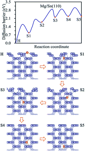 | ||
| Fig. 3 Diffusion energy profile for Mg magnesiation into the surface and subsurface sites of Sn(110) and the atomic geometries at local minimum points in the profile. | ||
3.3 Adsorption and magnesiation Mg into Sn(111) surface
Three possible adsorption sites, i.e. H, T1 and T2 sites, were considered for the adsorption of Mg on the Sn(111) surface as shown in Fig. 1c. The H is above the center of hexagon structure composed of six non-plane Sn atoms. T1 and T2 sites are above the top of topmost and sub-high surface Sn atoms, respectively. The adsorption energies for Mg at H, T1, and T2 sites are listed in Table 1. The Mg prefers to occupy the H site on the Sn(111) surface with an adsorption energy of −1.62 eV. T2 site is less stable adsorption site, which is with an adsorption energy of 0.16 eV higher than the H site. The T1 site is not favorable adsorption site for Mg with the adsorption energy of −0.81 eV.The magnesiation of Mg into Sn through the (111) surface was studied by considering the diffusion of Mg along the H → S1 → S2 → S3 → S4 → S5 path, and the diffusion energy profile was shown in Fig. 4. A similar diffusion behavior was found for Mg magnesiation into Sn through the (111) surface as through the (100) and (110) surfaces. The diffusion energy barrier is much higher for Mg diffuses from the surface to the subsurface of Sn, and the diffusion energy barrier is 1.27 eV for Mg along the H → S1 path. The diffusion barrier decreases as Mg diffuses inside the Sn. The diffusion energy barriers are 0.56 and 0.54 eV for Mg diffuses along S1 → S2 and S3 → S4 path, respectively. And they are 1.21 and 0.91 for Mg diffuses along S2 → S3 and S4 → S5 path, respectively. So the H → S1 path is the rate-limiting step upon Mg intercalated into Sn through the (111) surface. It is noticed that the diffusion of Mg inside the Sn through the (111) crystal facet with small and large diffusion energy barriers repeatedly. As shown in Fig. 4, the diffusion energy barriers of Mg diffuses are 0.56 eV (small) for S1 → S2, 1.21 eV (large) for S2 → S3, 0.54 eV (small) for S3 → S4, and 0.91 eV (large) for S4 → S5. The same diffusion behavior has been observed for Li diffusion into Si17 and Sn19 through the (111) surface. The diffusion of Mg inside the Sn is through jumping from one tetrahedral site to an adjacent one by passing through a hexagonal site. As the hexagon is perpendicular to the (111) surface, it is easy for the relaxation of atoms, which induces a small diffusion barrier. Whereas the hexagon is parallel to the (111) surface, it is difficult for the relaxation of atoms, which induces a large diffusion energy barrier. So a small and large diffusion energy barriers repeatedly when Mg diffuses along the S1 → S2 → S3 → S4 → S5 path.
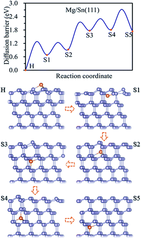 | ||
| Fig. 4 Diffusion energy profile for Mg magnesiation into the surface and subsurface sites of Sn(111) and the atomic geometries at local minimum points in the profile. | ||
3.4 Magnesiation of Mg2Sn(100), Mg2Sn(110) and Mg2Sn(111) surfaces
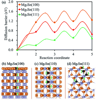
The crystalline Sn transforms to crystalline Mg2Sn upon the insertion of Mg ions, and re-formation of crystalline Sn for the de-magnesiated crystalline Mg2Sn,12 we further studied the surface magnesiation behavior of (100), (110), and (111) surfaces for crystalline Mg2Sn through a vacancy mechanism. Fig. 5a shows the diffusion energy profile for the magnesiation of Mg2Sn(100), Mg2Sn(110) and Mg2Sn(111) surfaces, and the corresponding diffusion paths (1 → 2 → 3 → 4 → 5 path) are shown in Fig. 5b, c, and d, respectively. Mg atom migrates from the Mg layer to the adjacent Mg layer by passing through an interstitial site located in the Sn layer through the Mg2Sn(100) surface. And the diffusion barriers are 1.15, 0.38, 0.48, and 0.47 eV for Mg diffuses from the outmost surface to the inside Mg layer along the 1 → 2 → 3 → 4 → 5 diffusion path through the Mg2Sn(100) surface. As Mg diffuses from one Mg–Sn layer to the adjacent Mg–Sn layer through Mg2Sn(110) surface, it needs to overcome energy barriers of 0.75, 0.42, 0.44, and 0.34 eV. The diffusion energy barriers are 0.20, 0.25, 0.36, and 0.42 eV for Mg diffuses into Mg2Sn through (111) surface. It can be seen from Fig. 5a that the surface diffusion is a rate-limiting step upon Mg intercalated into Mg2Sn through (100) and (110) surfaces, whereas the surface magnesiation of Mg2Sn(111) surface is easier than (100) and (110) surfaces.From the above results, it can be seen that the diffusion energy barrier is higher for Mg diffuses from the surface to subsurface compared with the inside diffusion as Mg intercalated into Sn though (100), (110) and (111) surfaces and into Mg2Sn through (100) and (110) surfaces. When Mg was intercalated into the Sn, the diffusion process from the surface to the subsurface is the rate-limiting step. Comparing the diffusion behavior of Mg into Sn through (100), (110) and (111) surfaces, the one from the (100) surface is easier than (110) and (111) surfaces. The intercalation of Mg into Mg2Sn through (111) surface is easier than through (100) and (110) surfaces. The surface magnesiation should be considered for Sn as anode for MIBs, especially when anode materials are decreased to nanoscale, and the surface electrochemical reaction is a key factor that affects battery performance. Surface modification such as metal doping30 could be used to reduce the surface magnesiation barrier.
4. Conclusion
In conclusion, Mg magnesiation into α-Sn and Mg2Sn through (100), (110) and (111) surfaces was investigated using density functional theory. The diffusion energies barriers are in the range 0.63–1.05, 0.68–1.58 and 0.54–1.27 eV for Mg diffuses in Sn along the <100>, <110> and <111> directions, respectively. Mg diffuses faster along the <100> direction than along <110> and <111> directions. The diffusion energy barriers are 1.05, 1.58 and 1.27 eV for Mg diffuses from the surface to subsurface by penetrating Sn(100), Sn(110) and Sn(111) surfaces, respectively, which are larger than the value of Mg diffuses inside Sn. The surface magnesiation is also the rate-limiting step upon Mg intercalated into Mg2Sn though (100) and (110) surfaces. The Mg diffusion from the surface to subsurface becomes the rate-limiting step for Sn used as anode for MIBs. Surface modification to improve the magnesiation behavior should be considered for Sn as anode for MIBs, especially anode materials are decreased to nanoscale.Conflicts of interest
There are no conflicts of interest to declare.Acknowledgements
This work was financially supported by the National Natural Science Foundation of China (11474047) and the Fundamental Research Funds for the Central Universities (ZYGX2016J202). This work was carried out at National Supercomputer Center in Tianjin, and the calculations were performed on TianHe-1(A).References
- D. Aurbach, Y. Gofer, A. Schechter, O. Chusid, H. Gizbar, Y. Cohen, M. Moshkovich and R. Turgeman, J. Power Sources, 2001, 97, 269–273 CrossRef.
- Y. G. D. Aurbach, Z. Lu, A. Schechter, O. Chusid, H. Gizbar, Y. Cohen, V. Ashkenazi, M. Moshkovich, R. Turgeman and E. Levi, J. Power Sources, 2001, 97, 28–32 CrossRef.
- M. M. Huie, D. C. Bock, E. S. Takeuchi, A. C. Marschilok and K. J. Takeuchi, Coord. Chem. Rev., 2015, 287, 15–27 CrossRef CAS.
- J. S. Kim, W. S. Chang, R. H. Kim, D. Y. Kim, D. W. Han, K. H. Lee, S. S. Lee and S. G. Doo, J. Power Sources, 2015, 273, 210–215 CrossRef CAS.
- E. Levi, Y. Gofer and D. Aurbach, Chem. Mater., 2010, 22, 860–868 CrossRef CAS.
- H. D. Yoo, I. Shterenberg, Y. Gofer, G. Gershinsky, N. Pour and D. Aurbach, Energy Environ. Sci., 2013, 6, 2265–2279 CAS.
- S. Rasul, S. Suzuki, S. Yamaguchi and M. Miyayama, Electrochim. Acta, 2013, 110, 247–252 CrossRef CAS.
- Y. L. Liang, R. J. Feng, S. Q. Yang, H. Ma, J. Liang and J. Chen, Adv. Mater., 2011, 23, 640–644 CrossRef CAS PubMed.
- C. Ling, R. Zhang, T. S. Arthur and F. Mizuno, Chem. Mater., 2015, 27, 5799–5807 CrossRef CAS.
- W. Jin, Z. Wang and Y. Q. Fu, J. Mater. Sci., 2016, 51, 7355–7360 CrossRef CAS.
- D. L. Aurbach, Z. Lu, A. Schechter, Y. Gofer, H. Gizbar, R. Turgeman, Y. Cohen, M. Moshkovich and E. Levi, Nature, 2000, 407, 724–727 CrossRef CAS PubMed.
- N. Singh, T. S. Arthur, C. Ling, M. Matsui and F. Mizuno, Chem. Commun., 2013, 49, 149–151 RSC.
- Z. Wang, Q. Su, J. Shi, H. Deng, G. Q. Yin, J. Guan, M. P. Wu, Y. L. Zhou, H. L. Lou and Y. Q. Fu, ACS Appl. Mater. Interfaces, 2014, 6, 6786–6789 CAS.
- Y. H. Xu, Q. Liu, Y. J. Zhu, Y. H. Liu, A. Langrock, M. R. Zachariah and C. S. Wang, Nano Lett., 2013, 13, 470–474 CrossRef CAS PubMed.
- J. Chen and F. Y. Cheng, Acc. Chem. Res., 2009, 42, 713–723 CrossRef CAS PubMed.
- O. I. Malyi, T. L. Tan and S. Manzhos, J. Power Sources, 2013, 233, 341–345 CrossRef CAS.
- S. C. Jung and Y. K. Han, Phys. Chem. Chem. Phys., 2011, 13, 21282–21287 RSC.
- P. Kaghazchi, J. Chem. Phys., 2013, 138, 054706 CrossRef PubMed.
- S. C. Jung and Y. K. Han, Phys. Chem. Chem. Phys., 2013, 15, 13586–13592 RSC.
- T. Slusarski, B. Brzostowski, D. Tomecka and G. Kamieniarz, Acta Phys. Pol., A, 2010, 118, 967–968 CrossRef CAS.
- G. Kresse and J. Furthmuller, Comput. Mater. Sci., 1996, 6, 15–50 CrossRef CAS.
- G. Kresse and D. Joubert, Phys. Rev. B: Condens. Matter Mater. Phys., 1999, 59, 1758–1775 CrossRef CAS.
- N. Troullier and J. L. Martins, Phys. Rev. B: Condens. Matter Mater. Phys., 1991, 43, 8861–8869 CrossRef.
- C. Kittel, Introduction to Solid State Physics, New York, 2005 Search PubMed.
- V. Fiorentini and M. Methfessel, J. Phys.: Condens. Matter, 1996, 8, 6525–6529 CrossRef CAS.
- B. Peng, F. Cheng, Z. Tao and J. Chen, J. Chem. Phys., 2010, 133, 034701 CrossRef PubMed.
- J. Neugebauer and M. Scheffler, Phys. Rev. B: Condens. Matter Mater. Phys., 1992, 46, 16067–16080 CrossRef CAS.
- Y. Morikawa, K. Kobayashi and K. Terakura, Surf. Sci., 1993, 283, 377–382 CrossRef CAS.
- T. L. Chan and J. R. Chelikowsky, Nano Lett., 2010, 10, 821–825 CrossRef CAS PubMed.
- B. R. Long, M. K. Y. Chan, J. P. Greeley and A. A. Gewirth, J. Phys. Chem. C, 2011, 115, 18916–18921 CAS.
| This journal is © The Royal Society of Chemistry 2017 |

