DOI:
10.1039/C7RA07727K
(Paper)
RSC Adv., 2017,
7, 42339-42344
Microaxicave colour analysis system for fluoride concentration using a smartphone†
Received
14th July 2017
, Accepted 27th August 2017
First published on 1st September 2017
Abstract
People in northern China use underground water as their major water source. The fluoride in the water is threatening the health of the people. We demonstrate a fluoride concentration measurement method using a smartphone and microaxicave grating. The hue–value relation of the image captured by the smartphone and the results of a commercial spectrophotometer show great consistency, which indicates that the resolution of fluoride concentration of our system approaches 80 μg L−1. We also use a rigorous coupled-wave analysis (RCWA) method, to calculate the diffractive efficiency of the microaxicave and it shows better performance than some commercial gratings in diffractive efficiency. Our fluoride detection system does not need any additional power or light supply and has a volume of 264 cm3 and a weight of 140 g, which can bring great convenience to fluoride detection in rural areas.
Introduction
Fluoride is an essential ion in the human body. A moderate intake of fluoride can prevent dental caries.1 However, excess doses of fluoride may cause serious harm to the human body such as skeletal abnormalities and lesions of the endocrine glands.2,3 In order to prevent these potential detriments to the human body, the World Health Organization (WHO) sets the guideline concentration to be 1.5 mg L−1,4 while the maximum allowable concentration in drinking water is 1.0 mg L−1 in most parts of China and 1.2 mg L−1 in remote rural areas.5 Fluorine is the 13th most abundant element in the earth's crust (625 mg kg−1) and exists in trace amounts in almost all groundwater throughout the world.6 In the rural areas of northern China, e.g. Tianjin and Hebei province, the fluoride concentration in groundwater may exceed 3 mg L−1; as the groundwater is the major source of drinking water, the daily intake of fluoride may exceed the allowable level and consequently cause huge health problems in the long term.7 The detection of fluoride concentration is becoming an urgent issue in these areas of China.
The conventional ways to measure fluoride concentration are fluorine selective electrode8 and fluorine reagents spectrophotometry.9 They both are time consuming and involve large experimental equipment and trained technicians, which may not always available in the rural areas. Some rapid fluoride identification instruments are reported these years.10,11 These instruments need additional light and power source, which may bring inconvenience in on-site measurement.
According to Pew Research Centre, 58% of Chinese people are using smartphone and the percentage is increasing every year.12 Modern smartphones are equipped with CPU, GPU and memory of great performance. Furthermore, many sensors are integrated in the smartphone, such as complementary metal oxide semiconductor (CMOS), ambient light sensor and compass and etcetera. By using these sensors, researchers are able to design plenty of equipment in many fields such as spectroscopy,13–15 fluorescence spectroscopy,16–18 microscopy,19,20 pH sensing,21 surface plasmon resonance detection,22,23 phase detection.24 These progresses in material detection justified that smartphone-based detection devices are portable, low-cost and powerful. Camera sensors of a smartphone can capture the information of all visible wavelengths. Smartphone itself is portable and popular in all scenario.
Dhillon et al.25 summarized the recent progress of fluoride detection. Of all the detection methods, colorimetric probes based on a specific reaction are more selective and stable in fluoride detection. Moreover, measurements toward the optical physical change of the sample is efficient and convenient, which fits the situation of rural area. Fluorescent or colorimetric chemosensors based on polymers were developed due to their simplicity of use, signal amplification, easy fabrication into devices, and combination of different outputs.26 Liu et al.27 synthesized a new chemosensor displaying high selectivity and sensitivity to F− at 610 nm. Deka et al.28 developed a high-resolution ligand for fluoride detection at 536 nm. Solé et al.29 synthesized a bidentate borane as colorimetric fluoride ion sensor at 363 nm. Recently, fluoride concentration detectors using a mobile phone are reported. Levin et al.30 analyse the colour of the dyed fluoride solution and Hussain et al. present a fluoride sensor using the ambient light sensor of the smartphone. These smartphone-based devices are compact and low-cost. These devices take advantages of the great function of smartphone, which makes them efficient in fluoride detection. However, they just focus on the intensity of the light at a certain wavelength or a specific dyed colour. Progress in chemistry has produced many new high-resolution fluoride sensors in different wavelengths mentioned above. A fluoride detector considering all the visible colours is necessary to match that progress in chemistry.
We designed and built a fluoride concentration detection system to analyse the light intensity of dyed fluoride solution in all hue values. A quartz microaxicave fabricated with grey-scale direct laser writing and inductively coupled plasma etching32 disperses the incident light to chromatic rings of different intensity and position. Firstly, we records the pattern with the CMOS camera of the smartphone. Then we process the image in hue-saturation-value (HSV) colour space to generate value–hue relation curves, from which we find that the peak of the curves decreases linearly as the concentration of fluoride enhances from 80 μg L−1 to 640 μg L−1. Our system concerning all hue values is of the advantages of small size, mass and high resolution. With the popularity of smartphone, and the built-in mobile network system, our detection system will make onsite distributed fluoride detection easier in northern China.
Methods
A spectrometer simulation and structure
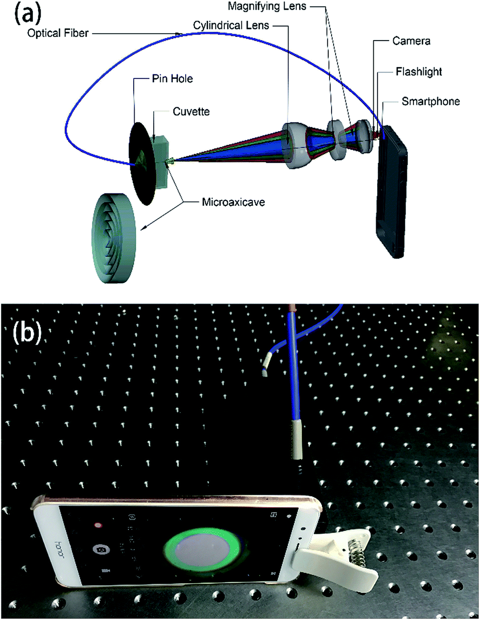
The schematic design of the system is shown in Fig. 1. Light signal from the flashlight of a smartphone (Huawei Honor V9) passes through a pinhole of diameter 1.0 mm using an optical fibre. The light signal coming out of the pinhole passes through a quartz cuvette (path length 10 mm) and a plasma-etched microaxicave to generate circular diffraction pattern and then collimated by a plano-convex lens of focal length 30 mm. In order to match the size of the camera sensor, we magnify the collimated light to match the sensor size of the camera to the smartphone by a set of magnifying lens of focal lens 4 mm. Finally, we use the CMOS camera of the smartphone to capture the diffractive pattern. Before taking the picture of the diffractive pattern, the ISO, shutter speed, focal length and the exposure value are locked after putting an empty cuvette into our system. The final system, which is shown in Fig. 1(b), measures 40 mm × 40 mm × 165 mm in size and 140 g in weight.
 |
| | Fig. 1 (a) Layout of the microaxicave portable spectrometer system, the downside of (a) is the amplified sketch of microaxicave. (b) Snapshot of the portable spectrometer system. | |
Microaxicave analysis
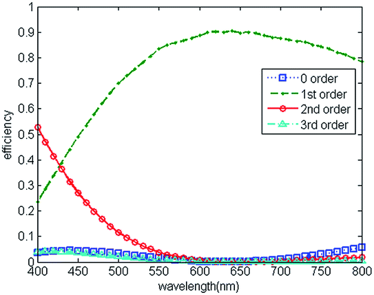
Blazed grating is commonly used in lab-used spectrometers,33 the diffraction efficiencies at blaze wavelength (around 500 nm) of blazed reflection gratings are typically around 75% and drop to 40% at 800 nm.34 Since the wavelengths of visible light range from 390–780 nm, we modify the structure parameters of microaxicave to obtain the highest diffraction efficiency at 632.8 nm.32 Compared with a blazed grating, the microaxicave is better in depressing the zero-order diffracting energy and focusing more incident energy to the first-order diffraction. Fig. 2 shows the RCWA results of the diffraction efficiency of microaxicave in the visible range,35,36 and Fig. 3 shows the diffraction pattern in our system. The microaxicave is optimized for the central wavelength of 632.8 nm. The first order diffraction efficiency is higher than 70% from 520 nm to 800 nm, while the second order diffraction efficiency is lower than 10% in this range, allowing higher light intensity passing through the microaxicave. Contrary to the linear pattern of the traditional grating, the diffractive pattern of the microaxicave is circular rings shown in Fig. 3.
 |
| | Fig. 2 Diffraction efficiency of microaxicave optimized for 632.8 nm calculated by RCWA. | |
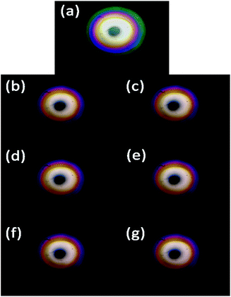 |
| | Fig. 3 Diffraction pattern of microaxicave captured by the camera of smartphone of the solution with (a) water and the dyed solution of fluoride concentration at (b) 0 μg L−1, (c) 80 μg L−1, (d) 160 μg L−1, (e) 320 μg L−1, (f) 480 μg L−1, (g) 640 μg L−1. | |
Sample preparation
We use the fluoride chromogenic reagent following the standardization enacted by the ministry of environmental protection of China9 to dye the fluoride aqueous solution (the specific preparation steps are listed in the ESI materials†). All chemicals except sodium fluoride, which is guaranteed grade, used in our work are of analytical grade and were used as received without further purification. The dye reagents were prepared following the same standardization.9 We dilute 0, 1, 2, 4, 6, 8 ml 2 μg L−1 standard fluoride solution (the specific preparation steps are listed in the ESI materials†) of the to 10 ml with deionized water and add 10 ml fluoride chromogenic reagent and dilute to 25 ml with deionized water in 25 ml volumetric flask to produce 0, 80, 160, 320, 480, 640 μg L−1 fluoride solution (Fig. 4) and orderly fill the cuvette to capture their diffraction pattern. In addition, we show the captured image by smartphone in Fig. 3 respectively. Because the fluoride dye reagent reacts with the fluoride ions in the solution and forms a blue complex compound, the colour of the dyed fluoride solution turns blue with the increase of the concentration of fluoride ions.
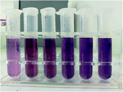 |
| | Fig. 4 The snapshot of the dyed solution from the left to right is 0 μg L−1, 80 μg L−1, 160 μg L−1, 240 μg L−1, 480 μg L−1 and 640 μg L−1. | |
Diffraction pattern processing
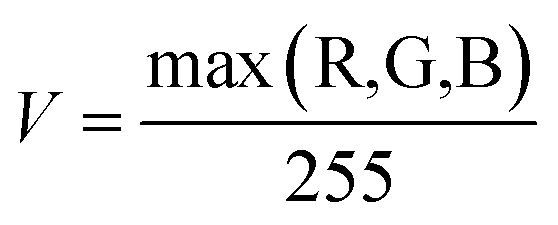
Tailed to the circular diffraction pattern of the microaxicave and character of the fluoride-dyed solution, we compiled an algorithm with MATLAB to extract the spectrum information of the sample by directly processing the circular diffractive pattern captured by smartphone camera. We know that the principle of our chromogenic reagent and some novel ways of measuring the concentration of fluoride are to dye the fluoride solution.27–29,37 We have to make colour become an independent parameter to measure the concentration. Therefore, we convert the image from RGB colour space to HSV colour space to analyse the colour change of the fluoride concentration. In HSV colour space, hue (H) represents the degree to which a stimulus can be described as red, green, blue, and yellow.38 We use hue to represent the sample's colour character. Saturation (S) represents the colourfulness of a stimulus relative to its own brightness. Value (V) represents the brightness of the colour. We convert the RGB colour space to HSV colour space by the following equations:| |
 | (1) |
if H is less than 0 then add 1 to H.
If max(R,G,B) − min(R,G,B) = 0 then H = 0.
| |
 | (2) |
| |
 | (3) |
where R, G and B stand for red channel, green channel and blue channel respectively. The value of
H,
S and
V is normalized to unity.
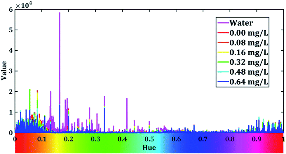
Then, we calculate the sum of V channel value across all the pixels of the captured image with different H value. After that, we draw V–H relation curves of different samples, and show them in Fig. 5.
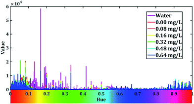 |
| | Fig. 5 V–H relation curves calculate by summing the intensity of all the pixels of V-channel in different hues. The rainbow ribbon on the hue axis represents the colour of this hue value assuming S and V equal to 1. | |
From Fig. 5, we can see that the intensity of the value is higher when the hue is around 0.2 when the cuvette is filled with water. The peak of water curve appears at 0.166. When we add the dyed solution to the cuvette, the value of hues decreases in 0.15 to 0.55 and different concentration of fluoride seems to have different peaks. This indicates our dyed fluoride solution have great ability to absorb light of yellow and green colours and it fit well with the fact that the dyed solution seems blue-purple in Fig. 4. In order to prevent the stray light effect, we apply a Gaussian low-pass filter to Fig. 5 to increase the signal to noise ratio (SNR). The low-pass filter is dimed as:
| |
 | (4) |
where
D0 is the cut-off frequency,
D denotes the distance between the point (
u,
v) and the cut-off frequency
D0. The process procedure is followed by:
| |
v(h) = ![[scr F, script letter F]](https://www.rsc.org/images/entities/i_char_e141.gif) −1((v0(h)) × E(u)) −1((v0(h)) × E(u))
| (5) |
where
v0 is the original
V–
H curve and
v is the filtered curve, and
and
−1 represent Fourier and inverse Fourier transform respectively.
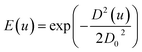
After the low-pass filter modify, hue–value relation figure is showed in Fig. 6.
 |
| | Fig. 6 V–H relation curves after a Gaussian low-pass filter when the cut-off frequency is 20. | |
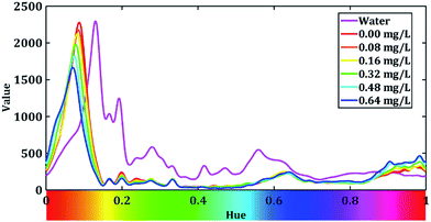
We can see that a peak present when the value of hue is around 0.1. Therefore, we zoom in the range of hue from 0 to 0.2 and the curves are shown in Fig. 7.
 |
| | Fig. 7 V–H relation curves of different fluoride concentration. | |
Results and discussion
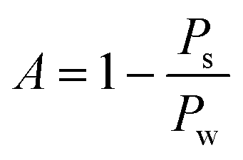
Fig. 7 shows that the peaks of our H–V curves present around 0.07 and the absorption peak the blue complex compound is around 620 nm.9 From the rainbow ribbon on the hue axis we can see that when hue equals to 0.07, the colour of it is close to the colour of the light whose wavelength is 620 nm. Fig. 7 also shows that the peak of the V–H decrease with the increase in the fluoride concentration. We extract the peak value of each H–V curves and dim the absorption rate of fluoride in our system as:| |
 | (6) |
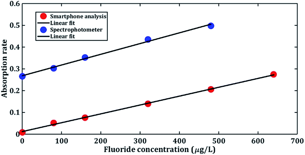
where A is the absorption rate, Ps is the peak value of the sample, Pw is the peak value of the water. Then we use linearly least square method to fit the absorption of each samples and show the results in Fig. 8. The coefficient of determination of the linear fitting is 0.9984, which means the absorption rate we dimed has a linear relation with the concentration of fluoride with the range 0.08 to 0.64 mg L−1. In addition, we use a UV spectrophotometer (UV5100B) following the rule of Chinese standard fluoride measurement method to test the fluoride concentration,9 the experimental result and the linear fitting are shown in Fig. 8 respectively. The coefficient of determination of this fitting is 0.9951.
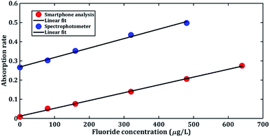 |
| | Fig. 8 The absorption rate of fluoride concentration using smartphone analysis and spectrometer. | |
From Fig. 8 we can see that the absorption rate measured by our system show great consistency with the spectrophotometer result indicating our system is able to measure the fluoride concentration of an 80 μg L−1 resolution. This fits the lower determination limit of the standardization of fluoride detection of China,9 proving that our system can be utilized to detect fluoride concentration of water samples in rural northern China. Chemosensors such as the BODIPY-based sensor27 can detect 0–60 μM. But the UV-vis spectrophotometer is not available for on-site detection. In addition, the coefficient of determination of our system ranges from 0–640 μg L−1 is higher than the coefficient of the smartphone-based fluoride detection sensors ranges from 0–100 μg L−1,31 which indicates that our system is stable and has a good linearity. In our work, we have composed the microaxicave dispersion element to a portable low-cost and low-weight smartphone accessory for fluoride detection. Combing with the flashlight, camera and computing ability of the smartphone, this system can be used to detect and quantify the fluoride concentration without additional power or light supply in any working environment. In addition, the hue–value computing method is suitable for all visible wavelengths, which permits our system operating in different chemosensors.
Conclusions
In summary, we build a small-sized, portable, on-site fluoride concentration detection system, which can measures the fluoride concentration with a resolution of 80 μg L−1, by using the flashlight of a cell phone as the light source, microaxicave grating as the dispersive device and the smartphone's CMOS sensor to collect the diffractive pattern. Tailored to the diffraction pattern of the microaxicave and the colour character of the chromogenic reagent, we draw hue-value relation curves from the diffractive pattern and dim an absorption rate of our system. We find that the absorption rate we dimmed increasing linearly with the increase in the fluoride concentration and show the same gradient with the absorption rate curve measured by spectrophotometer. This fluoride concentration detection system uses no electricity or light source rather than a smartphone. The northern China has few people and suffers a lot on the fluoride in the underground water. We believe that with great communication ability of smartphone, our system can make distributed detection and contribute to the detection of fluoride concentration in the northern China.
Conflicts of interest
There are no conflicts to declare.
Notes and references
- J. t. Cate, Eur. J. Oral Sci., 1997, 105, 461–465 CrossRef CAS PubMed.
- D. L. Ozsvath, Rev. Environ. Sci. Bio/Technol., 2009, 8, 59–79 CrossRef CAS.
- S. Roy and G. Dass, Resour. Environ., 2013, 3, 53–58 Search PubMed.
- T. Thompson, J. Fawell, S. Kunikane, D. Jackson, S. Appleyard, P. Callan, J. Bartram and P. Kingston, Chemical safety of drinking-water: assessing priorities for risk management, 2007 Search PubMed.
- Standards for drinking water quality, M. o. Health and S. Administration Report GB 5749, China, 2006.
- M. Amini, K. Mueller, K. C. Abbaspour, T. Rosenberg, M. Afyuni, K. N. Møller, M. Sarr and C. A. Johnson, Environ. Sci. Technol., 2008, 42, 3662–3668 CrossRef CAS PubMed.
- Y. Wang, L. X. Sheng, K. Li and H. Y. Sun, Journal of Water Resources & Water Engineering, 2008, 19, 10–14 Search PubMed.
- J. E. Harwood, Water Res., 1969, 3, 273–280 CrossRef CAS.
- Water quality—Determination of Fluoride—Fluorine reagents spectrophotometry, M. o. e. protection Report HJ 488, China, 2009.
- A. B. Pillai, B. Varghese and K. N. Madhusoodanan, Environ. Sci. Technol., 2012, 46, 404–409 CrossRef PubMed.
- W. Q. Yang and Y. Q. Guan, Chem. Reagents, 2014, 36, 446–448 CAS.
- J. Poushter, Smartphone Ownership and Internet Usage Continues to Climb in Emerging Economies, http://www.pewglobal.org/files/2016/02/pew_research_center_global_technology_report_final_february_22__2016.pdf, accessed 30. 6. 2017.
- Y. Wang, X. Liu, P. Chen, N. T. Tran, J. Zhang, W. S. Chia, S. Boujday and B. Liedberg, Analyst, 2016, 141, 3233–3238 RSC.
- C. Zhang, G. Cheng, P. Edwards, M.-D. Zhou, S. Zheng and Z. Liu, Lab Chip, 2016, 16, 246–250 RSC.
- M. A. Hossain, J. Canning, K. Cook and A. Jamalipour, Opt. Lett., 2016, 41, 2237–2240 CrossRef PubMed.
- M. A. Hossain, J. Canning, S. Ast, K. Cook, P. J. Rutledge and A. Jamalipour, Opt. Lett., 2015, 40, 1737–1740 CrossRef PubMed.
- A. J. Das, W. Akshat, K. Ishan and R. Ramesh, Sci. Rep., 2016, 6, 32504 CrossRef CAS PubMed.
- Q. Wei, H. Qi, W. Luo, D. Tseng, S. J. Ki, Z. Wan, Z. n. Göröcs, L. A. Bentolila, T.-T. Wu and R. Sun, ACS Nano, 2013, 7, 9147–9155 CrossRef CAS PubMed.
- D. Tseng, O. Mudanyali, C. Oztoprak, S. O. Isikman, I. Sencan, O. Yaglidere and A. Ozcan, Lab Chip, 2010, 10, 1787–1792 RSC.
- M. Kühnemund, Q. Wei, E. Darai, Y. Wang, I. Hernández-Neuta, Z. Yang, D. Tseng, A. Ahlford, L. Mathot and T. Sjöblom, Nat. Commun., 2017, 8, 13913 CrossRef PubMed.
- S. Dutta, D. Sarma, A. Patel and P. Nath, IEEE Photonics Technol. Lett., 2015, 27, 2363–2366 CrossRef CAS.
- P. Preechaburana, M. C. Gonzalez, A. Suska and D. Filippini, Angew. Chem., 2012, 124, 11753–11756 CrossRef.
- S. Dutta, K. Saikia and P. Nath, RSC Adv., 2016, 6, 21871–21880 RSC.
- I. Hussain and P. Nath, Appl. Opt., 2015, 54, 5739–5742 CrossRef CAS PubMed.
- A. Dhillon, M. Nair and D. Kumar, Anal. Methods, 2016, 8, 5338–5352 RSC.
- H. N. Kim, Z. Guo, W. Zhu, J. Yoon and H. Tian, Chem. Soc. Rev., 2011, 40, 79–93 RSC.
- J. Liu, X. He, J. Zhang, T. He, L. Huang, J. Shen, D. Li, H. Qiu and S. Yin, Sens. Actuators, B, 2015, 208, 538–545 CrossRef CAS.
- B. Deka and R. J. Sarma, Sens. Actuators, B, 2014, 197, 321–325 CrossRef CAS.
- S. Solé and F. P. Gabbaï, Chem. Commun., 2004, 1284–1285 RSC.
- S. Levin, S. Krishnan, S. Rajkumar, N. Halery and P. Balkunde, Sci. Total Environ., 2016, 551, 101–107 CrossRef PubMed.
- I. Hussain, K. U. Ahamad and P. Nath, Anal. Chem., 2016, 89, 767–775 CrossRef PubMed.
- D. Kuang and Z. Fang, Opt. Lett., 2010, 35, 2158–2160 CrossRef PubMed.
- C. Palmer and E. G. Loewen, Diffraction grating handbook, Newport Corporation New York, 2005 Search PubMed.
- Optometrics, 600g/mm Ruled 500 nm Blaze, http://www.optometrics.com//App_Themes/optometrics/pdfs/gratings/600g_mm_Ruled_500_nm_Blaze.pdf, accessed 25. 11. 2016.
- M. G. Moharam, T. K. Gaylord and J. R. Leger, J. Opt. Soc. Am. A, 1995, 12, 1026 CrossRef.
- G. M. Morris and P. Lalanne, J. Opt. Soc. Am. A, 1996, 13, 779–784 CrossRef.
- R. Badugu, J. R. Lakowicz and C. D. Geddes, J. Fluoresc., 2004, 14, 693–703 CrossRef CAS PubMed.
- M. D. Fairchild, Color Appearance Models, John wiley & sons, inc, 2013 Search PubMed.
Footnote |
| † Electronic supplementary information (ESI) available. See DOI: 10.1039/c7ra07727k |
|
| This journal is © The Royal Society of Chemistry 2017 |
Click here to see how this site uses Cookies. View our privacy policy here. 
 Open Access Article
 This Open Access Article is licensed under a
  a,
Dengfeng Kuang
a,
Dengfeng Kuang