 Open Access Article
Creative Commons Attribution 3.0 Unported Licence
Preparation and microwave absorbing property of carbon fiber/polyurethane radar absorbing coating
Zhao-hui Liua,
Rui Tao *a,
Ping Luoa,
Xin Shua and
Guo-dong Banb
aDept. of Chemistry & Material Engineering, Logistic Engineering University of PLA, Chongqing, 401311, China. E-mail: itaorui@163.com
bUnit 75752 of PLA, Guangdong 517000, China
First published on 28th September 2017
Abstract
To broaden the effective absorbing bandwidth of radar absorbing coating, carbon fiber/polyurethane radar absorbing coating (CFPURAC) is prepared with carbon fiber as filler and polyurethane as matrix, and then multi-layer CFPURAC is prepared with polyurethane coating as wave-transmitting material to match CFPURAC. Scanning electron microscope (SEM) and metallography microscope are employed to characterize the microstructure of filler and coating separately. Vector network analyzer (VNA) is adopted to test the radar wave reflectivity of coating. The results indicate that the absorbing property of coating is influenced by length and content of carbon fiber in the coating, and matching order and matching thickness of various absorbing layers to a great extent. In the optimum matching proposal, the effective absorbing bandwidth of coating is up to 13.1 GHz, and an effective absorption can be achieved within the range of 4.9 GHz to 18 GHz.
1. Introduction
As an important way to realize radar stealth technique, radar absorbing coating is of good effect, simple process, easy design and low cost, making it a critical technology to improve the stealth performance of equipment and a significant role in radar stealth technique.1,2 Recently all sorts of novel aircrafts and ships make use of radar absorbing coating extensively to enhance their anti-reconnaissance ability.3The application of short carbon fiber to absorbing coating as filling brings about many merits such as light weight, high strength and small addition, and figures out an important way how to develop radar absorbing coating.4–6 Nevertheless, carbon fiber is characterized with a bigger electrical conductivity, so its addition to coating should not be too high. Otherwise continuous conductive network is likely to form and reflect most of electromagnetic wave, and therefore the absorbing property of carbon fiber is refrained. In the majority of current studies, the absorbing property of carbon fiber is enhanced by activating treatment of carbon fiber,7,8 or modifying treatment of carbon fiber with nanometer iron powder,9 nickalloy,10 carbonyl iron powder11 and other materials while there are fewer studies on multi-layer matching radar absorbing coating which is prepared with carbon fiber radar absorbing coating as matrix.
In this paper, radar absorbing coating is prepared with radar short carbon fiber as absorbent and waterborne polyurethane as matrix resin, and then wave-transmitting layers are matched to systematically analyze the impact of the content, the length, and the matching thickness of carbon fiber on coating absorbing property.
2. Experiment
2.1. Materials
Polyurethane (PU) was Bayhydrol2648 waterborne polyurethane supplied by Yuanhe Chemical Co., Ltd. Shanghai China (nonvolatile content: 34–36%; density: 1.07g ml−1). Carbon fiber (CF) was the LS–CF–S carbon fiber purchased from Liso Composite Material Technology Co., Ltd. Shanghai China (tensile strength: 4900 MPa; tensile modulus: 230 GPa; elongation: 2.1%; density: 1.80 g cm3). Thickening agent was RM-8W thickening agent bought from Hongrun Chemical Co., Ltd., Guangzhou, China (nonvolatile content: 20.8–21.8%; density: 1.04g ml−1). Defoaming agent was BYK011 waterborne defoaming agent purchased from Sunny Chemicals Ltd., H. K., China (nonvolatile content: 29%; density: 0.8 g ml−1).2.2. Sample preparation
PU and CF were prepared by a fixed mass proportion. Then the 0.5 wt% thickening agent was added into the PU which was later processed with a disperser (SF smart dispersing sand mill) at the speed of 300 RPM for 10 min. After the thickening, the filler was put into the resin that was also dispersed at the same speed for 30 min. When uniformly dispersed, the mixture was placed into a mold by a fixed thickness. The curing process first proceeded at room temperature for 12 hours, then in oven by 50 °C for 24 hours.2.3. Testing
The microscopic morphology of CF was characterized with a scanning electron microscope (HITACHI-S3700N SEM, Hitachi Co., Ltd., Tokyo, Japan). The SEM was operated at an accelerating voltage of 15 kV.The phase analyses of CF was observed with a diffraction analyzer (DX-2700 X-ray, Fangyuan Instrument Co., Ltd., Dandong, China) with a working voltage of 35 kV and a working current of 25 mA. The step width was 0.02°.
The vector network analyzer (PNA E8363B vector network analyzer, Agilent Technologies Inc., California, USA) was used through NRL-arc method to test the reflectivity of electromagnetic wave (EM wave) in the 2–18 GHz frequency range at room temperature.
3. Results and conclusions
3.1. Microscopic morphology analysis
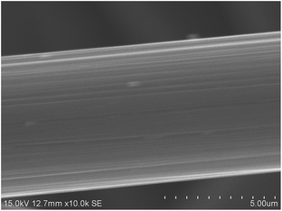
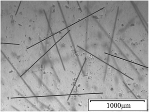
Fig. 1 indicates that the SEM image of CF. According to the image, the CF has a filamentous structure with an average diameter of 7 μm, and there are several small grooves on the surface which are beneficial to the combination of CF and matrix resin.Fig. 2 indicates that the metallurgical microscope image of CFPURAC. According to the image, the length of CFs exist certain difference for sake of the different gradient of CF in CFPURAC, but the CFs are randomly distributed in the matrix resin along different directions without obvious entanglement and reunion, and the spacing between CFs is relatively even.
3.2. XRD measurements of CF
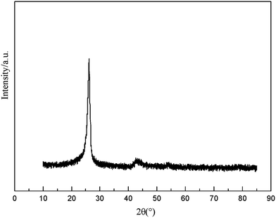
The XRD spectra of CF was shown in Fig. 3. An obvious peak appeared in 25°, which corresponded to the (002) crystal plane of the graphite structure, while the (110) crystal plane (44°) and (112) crystal plane (83°) of the graphite structure is not obvious, which indicated that the CF is a non-graphitized carbonaceous structure.3.3. Analysis of complex permittivity
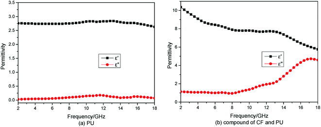
Fig. 4 shows the complex permittivity of PU and the compound of CF and PU. Fig. 4(a) presents that the real part of complex permittivity (ε′) of PU was no more than 2.8 which means the reflection of PU on microwave is weaker, and the imaginary part of complex permittivity (ε′′) of PU was close to 0, indicating the PU almost does not consume microwaves. Fig. 4(a) presents that the real part and the imaginary part of complex permittivity both increased after CF was added to PU, as the frequency goes up from 2 GHz to 18 GHz, the real part of complex permittivity dropped from 10.3 to 5.8 and the imaginary part of complex permittivity rose from 1.1 to 4.6, which indicates the compound of CF and PU have the frequency response effect.3.4. Absorbing property of double-layer CFPURAC
Single-layer CFPURAC just contains a small number of short CF, leading to smaller permittivity and dielectric loss tangent, so the absorbing property is very weak while it is used alone. According to general matching law and transmission line theory, after the matching of single-layer absorbing coating and wave-transmitting material, reflection factor of complex coating can be expressed as:12
 | (1) |
 | (2) |
In eqn (1) and (2), Zin means equivalent input impedance of complex coating; Z0 means input impedance of free space; Z1 means characteristic impedance of CF coating; Z2 means transmission line characteristic impedance; d1 means thickness of single-layer absorbing coating; d2 means thickness of wave-transmitting material; γ1, γ2 means propagation constant, which can be expressed: γ = α + jβ. α and β represent attenuation factor and phase factor individually:
 | (3) |
 | (4) |
In eqn (3) and (4),  and
and  stand for dielectric loss tangent and magnetic loss tangent separately, and d = λ/4 = π/2β = π/2β1 + π/2β2 under the optimum matching condition.13
Eqn (1)–(4) indicate that matching PUCFAC with wave-transmitting material can effectively improve the absorbing property of coating.
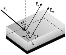
According to the radar absorbing coating's reflecting and absorbing model, when the microwave (Ei) reached the coating's front surface, part of the microwave (Er) would be reflected back into the air by the surface, the other part (Et) would penetrate into the coating. After going through consumption process by the coating, the leftover microwave (Ee) would be reflected back into the air. If the consumed microwave is assumed to be El, then the entire process will be like Fig. 5.
The energy relations in Fig. 5 are Ei = Er + Et and Et = El + Ee. If Er and Ee have equal or very nearly equal amplitudes and opposite phase, we see the destructive interference with Er and Ee. For double-layer CFPURAC, the amplitude of Er and Ee can be controlled by adjusting the content and length of CF, while the phase difference between Er and Eecan be controlled by adjusting the matching thickness at a certain frequency, to attain destructive interference and achieve good microwave absorption.
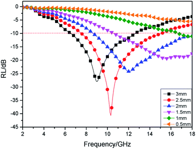
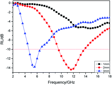
Fig. 7 is reflectivity of double-layer CFPURAC (CF content: 0.03 wt% and length: 3 mm) with different matching thickness (the thickness of PUC). During the transmission of microwave in the coating, the effective thickness becomes smaller with a lower frequency and a longer wave length. Accordingly, any change of effective thickness will cause the variance of matching conditions of interface impedance. As the frequency varies, there exists a peak for absorbing property.14 Seen from Fig. 6, while the matching layer thickness increased from 0.5 mm to 3 mm gradually, the maximum absorption peak of complex coating moved from high frequency to low frequency bit by bit. In the S-band (2–4 GHz) and C-band (4–8 GHz), with the increase of matching thickness, coating reflectivity dropt gradually; when the matching thickness was same, reflectivity kept decreasing with the ascending of frequency. In the X-band (8–12 GHz), the sudden change of coating reflectivity curve took place with the change of matching thickness. While the matching thickness was 2.5 mm, reflectivity came to the minimum peak value, which was −41 dB and reflectivity <−10 dB within the whole X-band. In the Ku-band (12–18 GHz), reflectivity fell first and then ascended with a minimum peak value of −24.3 dB, while the matching thickness increased. Once the matching thickness was 1.5 mm or 2 mm, reflectivity within the whole Ku-band was <–10 dB. In 2–18 GHz, the minimum peak value reached the minimum (−41 dB) while the matching thickness was 2.5 mm, the effective absorbing bandwidth (reflectivity < −10 dB) reached the maximum (8.6–18 GHz) while the matching thickness was 2.5 mm.
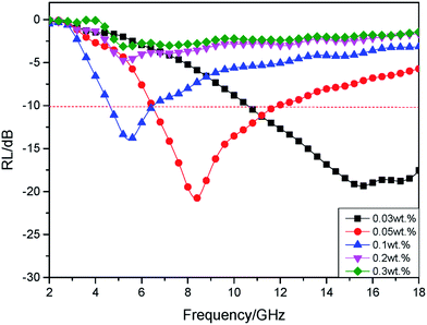
Table 1 shows absorbing properties of double-layer CFPURAC with different CF contents (CF length is 3 mm). Seen from the data in the table, although absorbing properties went through big changes under different matching thicknesses, the maximum absorbing peak frequency tended to decrease and the effective absorbing band moved to low frequency when CF content went up. Once CF content was over 0.2 wt%, the effective absorbing properties cannot be achieved, regardless of matching thickness. The increase of CF content results in a larger electron concentration around CF and a smaller gap between CFs. And then part of high-energy electrons could transcend surface potential barrier and generate electric current, which cause the increase of permittivity and the decrease of input impedance, making double-layer CFPURAC has a better matching performance at a low frequency. However, when CF content is excessive, permittivity keeps growing so as to cause the failure of impedance matching within 2 to 18 GHz.16,17
| Matched thickness (mm) | Content of CF | Lowest reflectivity (dB) | Frequency of maximum absorption (GHz) | Effective absorption frequency (GHz) |
|---|---|---|---|---|
| 1 | 0.03 wt% | 5.5 | 17.5 | — |
| 0.05 wt% | 7.8 | 15.7 | — | |
| 0.1 wt% | 5.2 | 11.2 | — | |
| 0.2 wt% | 3.3 | 7.5 | — | |
| 0.3 wt% | 2.7 | 7.2 | — | |
| 2 | 0.03 wt% | 19.4 | 15.5 | 10.5–18 |
| 0.05 wt% | 20.8 | 8.3 | 6.5–11.9 | |
| 0.1 wt% | 14 | 5.5 | 4.6–6.5 | |
| 0.2 wt% | 4.7 | 5.3 | — | |
| 0.3 wt% | 3.1 | 5.2 | — | |
| 3 | 0.03 wt% | 41 | 10.3 | 7.5–15 |
| 0.05 wt% | 22 | 6.7 | 5.4–9 | |
| 0.1 wt% | 13.2 | 5 | 4.5–5.7 | |
| 0.2 wt% | 3.9 | 4.8 | — | |
| 0.3 wt% | 2.6 | 4.7 | — |
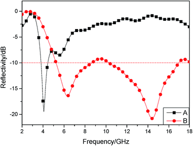
Table 2 shows absorbing properties of double-layer CFPURAC with different CF lengths (matching thickness is 2 mm) under a certain fiber content. See from the date in the table, while CF length increased, the maximum absorbing peak and the effective absorbing band moved to low frequency. Once CF content was less than 0.1 wt%, coating absorbing property was enhanced increasingly with the increase of CF length, but coating gained the effective absorbing property only when CF length was up to 3 mm; when CF content was between 0.1 wt% and 0.2 wt%, absorbing property first increased and then dropt with the increase of CF length, and the best absorbing property was observed once CF length gets to 2 mm; in the case that CF content exceeded 0.2 wt%, absorbing property dropt gradually with the increase of CF length, and double-layer CFPURAC already had a better absorbing property with CF which was 1 mm long. When CF content is lower, for shorter CF, there is an excessively short distance for induced current incurred by microwave to flow along fiber, which cannot act on microwave effectively. By enlarging the length of CF, fiber draw ratio is increased and the ability of fiber to form the conductive network in matrix resin is enhanced. When CF content is higher, mutual contact of fibers in a smaller area increases the flow distance of induced current, but if fiber is too long at this point, it is likely to form a continuous conductive network inside coating and cause difficulties to microwave absorption.18
| Content of CF (mm) | Length of CF (mm) | Lowest reflectivity (dB) | Frequency of maximum absorption (GHz) | Effective absorption frequency (GHz) |
|---|---|---|---|---|
| 0.03 wt% | 1 | −1.4 | 18 | — |
| 2 | −4.7 | 18 | — | |
| 3 | −19.4 | 15.5 | 10.6–18 | |
| 0.05 wt% | 1 | −2.9 | 18 | — |
| 2 | −11.9 | 12.6 | 11.6–14.8 | |
| 3 | −20.1 | 8.3 | 6.4–11.9 | |
| 0.1 wt% | 1 | −8.3 | 18 | — |
| 2 | −14.4 | 11.7 | 9.6–13.8 | |
| 3 | −13.9 | 5.4 | 4.6–6.5 | |
| 0.2 wt% | 1 | −13.9 | 14 | 12.1–16.1 |
| 2 | −39.8 | 6.5 | 5.6–8.3 | |
| 3 | −4.8 | 5.3 | — | |
| 0.3 wt% | 1 | −38.4 | 11.4 | 9.8–13.9 |
| 2 | −14.5 | 5.7 | 4.9–7.3 | |
| 3 | −3.2 | 5.4 | — |
3.5. Absorbing property of four-layer CFPURAC
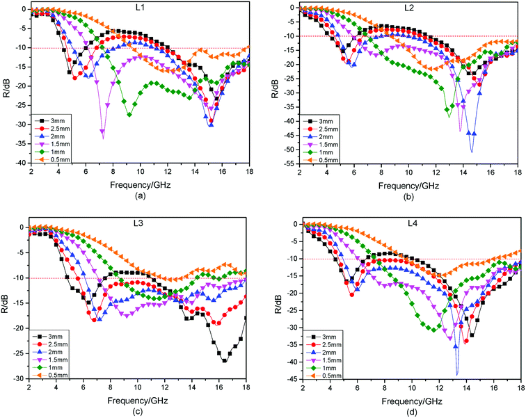
According to the analysis of 2.3, compared with single-layer PUCFAC, double-layer PUCFAC has a much better absorbing property, but in general, the effective absorbing bandwidth is narrower. Therefore, double-layer PUCFAC is sorted as high frequency absorbing layer and low frequency absorbing layer. Four-layer CFPURAC is prepared by matching high frequency absorbing layer with low frequency absorbing layer to broaden the effective absorbing bandwidth of coating. Table 3 and Table 4 individually present CF length and content of selected high frequency absorbing layer and low frequency absorbing layer.| Serial Number | H1 | H2 | H3 | H4 |
|---|---|---|---|---|
| CF Length | 1 mm | 1 mm | 2 mm | 2 mm |
| CF Content | 0.1 wt% | 0.2 wt% | 0.05 wt% | 0.1 wt% |
| Serial Number | L1 | L2 | L3 | L4 |
|---|---|---|---|---|
| CF Length | 2 mm | 2 mm | 3 mm | 3 mm |
| CF Content | 0.2 wt% | 0.3 wt% | 0.05 wt% | 0.1 wt% |
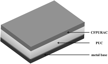
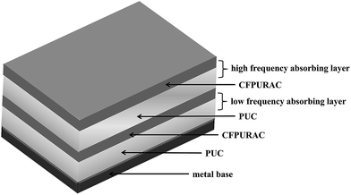
It is learnt for analysis above that four-layer CFPURAC has a better overall absorbing property while high frequency absorbing layer is upper and low frequency absorbing layer is lower, and the matching diagram of four-layer CFPURAC is showed in Fig. 11, and the thickness of CFPURACs are 0.5 mm.
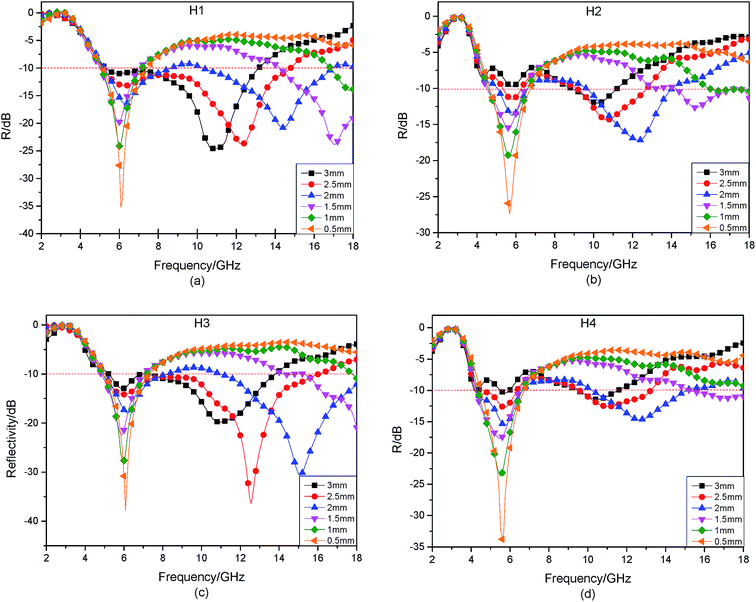
Fig. 12(a) indicates that coating absorbing property is the best when using H1 as high frequency absorbing layer, which has a matching thickness of 2 mm. And reflectivity is lower than −10 dB at both 5.3 to 8.6 GHz and 10.3 to 16.9 GHz. The effective absorbing bandwidth reaches 9.9 GHz. Fig. 12(b) shows that coating absorbing property is the best when using H2 as high frequency absorbing layer, which has a matching thickness of 2 mm. And reflectivity is lower than −10 dB at both 5.2 to 6.5 GHz and 9.8 to 13.9 GHz. The effective absorbing bandwidth reaches 5.4 GHz. Fig. 12(c) presents that coating absorbing property is the best when using H3 as high frequency absorbing layer, which has a matching thickness of 2 mm. And reflectivity is lower than −10 dB at both 5 to 8.2 GHz and 10 to 18 GHz. The effective absorbing bandwidth reaches 11.2 GHz. Fig. 12(d) indicates that coating absorbing property is the best when using H4 as high frequency absorbing layer, which has a matching thickness of 2 mm. And reflectivity is lower than −10 dB at both 4.3 to 6.5 GHz and 10.2 to 15.1 GHz. The effective absorbing bandwidth reaches 7.1 GHz. Therefore, coating has the best overall absorbing property at 2 to 18 GHz while using H3 as high frequency absorbing layer, which has a matching thickness of 2 mm.
Fig. 13(a) indicates that coating absorbing property is the best when using L1 as low frequency absorbing layer, which has a matching thickness of 1.5 mm. And reflectivity is lower than −10 dB at 6.1 to 18 GHz. The effective absorbing bandwidth reaches 11.9 GHz. Fig. 13(b) shows that coating absorbing property is the best when using L2 as low frequency absorbing layer, which has a matching thickness of 1.5 mm. And reflectivity is lower than −10 dB at 5.9 to 18 GHz. The effective absorbing bandwidth reaches 12.1 GHz. Fig. 13(c) presents that coating absorbing property is the best when using L3 as low frequency absorbing layer, which has a matching thickness of 2.5 mm. And reflectivity is lower than −10 dB at 5.6 to 18 GHz. The effective absorbing bandwidth reaches 12.4 GHz. Fig. 13(d) indicates that coating absorbing property is the best when using L4 as low frequency absorbing layer, which has a matching thickness of 2.5 mm. And reflectivity is lower than −10 dB at 4.6 to 18 GHz. The effective absorbing bandwidth reaches 13.4 GHz. Therefore, coating has the best overall absorbing property at 2 to 18 GHz while using L4 as low frequency absorbing layer, which has a matching thickness of 2 mm. Then optimum matching proposal of four-layer matching CFPURAC is: H3 is used as high frequency absorbing layer with matching thickness of 2 mm; L4 is used as low frequency absorbing layer with matching thickness of 2 mm.
4. Conclusion
(1) Double-layer CFPURC is prepared with PUC as isolating layer to match CFPURC, in order to enhance absorbing property of CFPURC. By adjusting the length and the content of CF in the coating, the effective absorption of four-layer CFPURAC was achieved in the C-band, the X-band and the Ku-band.(2) Four-layer CFPURC is prepared based on double-layer CFPURC. High frequency absorbing layer is in a high position while low frequency absorbing layer is in a low position. Absorbing property of high frequency absorbing layer in a high position and low frequency absorbing layer in a low position is much better than that of high frequency absorbing layer in a low position and low frequency absorbing layer in a high position.
(3) The optimum matching proposal of four-layer CFPURC are, from top to bottom, CFPURAC with thickness of 0.5 mm and 0.05 wt% 2 mm CF, PUC with thickness of 2 mm, CFPURAC with thickness of 0.5 mm and 0.1 wt% 3 mm CF, PUC with thickness of 2 mm.
Conflicts of interest
There are no conflicts to declare.References
- G. S. Bae and Y. K. Che, Microw. Opt. Technol. Lett., 2014, 56(8), 1907–1910 CrossRef.
- Z. P. Deng, Z. H. Liu, G. Z. Zhou and H. Zhang, J. Funct. Biomater., 2012, 43, 335–338 CAS.
- D. G. Holtby, K. L. Ford, and B. Chambers, IET Radar Sonar & Navigation, 2011, vol. 5, 4, pp. 483–488 Search PubMed.
- M. Tehrani, A. Y. Boroujeni, T. B. Hartman, T. P. Haugh, S. W. Case and M. S. Al-Haik, Compos. Sci. Technol., 2013, 75(2), 42–48 CrossRef CAS.
- K. Zhang, G. Zhang, B. Liu, X. Wang, S. Long and J. Yang, Compos. Sci. Technol., 2014, 98(16), 57–63 CrossRef CAS.
- S. Rahmanian, A. R. Suraya, M. A. Shazed, R. Zahari and E. S. Zainudin, Mater. Des., 2014, 60, 34–40 CrossRef CAS.
- T. C. Zou, N. Q. Zhao and C. S. Shi, J. Funct. Mater. Devices, 2007, 13(1), 54 CAS.
- T. Zou, N. Zhao, C. Shi and J. Li, Bull. Mater. Sci., 2011, 34(1), 75–79 CrossRef CAS.
- Y. Wang, A. Shah, H. Huang, F. Xue, L. Zhang, X. Dong and L. Zhang, Chin. J. Mater. Res., 2015, 29(2), 81–87 CAS.
- Y. Liu and C. Qiang, Bull. Mater. Sci., 2015, 38(7), 1673–1678 CrossRef CAS.
- Z. Wang, K. Li, C. Wang and J. Xie, J. Chin. Ceram. Soc., 2011, 39(1), 69–74 CAS.
- F. C. Seman, and R. Cahill, Rf and Microwave Conference, IEEE, 2012, pp. 373–376 Search PubMed.
- M. Cao, R. Qin, C. Qiu and J. Zhu, Mater. Des., 2003, 24(5), 391–396 CrossRef.
- M. S. Cao, W. L. Song, Z. L. Hou, B. Wen and J. Yuan, Carbon, 2010, 48(3), 788–796 CrossRef CAS.
- G. Shen, Z. Xu and Y. Li, J. Magn. Magn. Mater., 2006, 301(2), 325–330 CrossRef CAS.
- W. L. Song, M. S. Cao, Z. L. Hou, X. Y. Fang, X. L. Shi and J. Yuan, Appl. Phys. Lett., 2009, 94(23), 233110 CrossRef.
- W. Liu, C. Wang, and Y. Qi, Saf EMC, 2011, pp. 13–14.
- B. Wen, M. S. Cao, Z. L. Hou, W. L. Song, L. Zhang, M. M. Lu and J. Yuan, Carbon, 2013, 65, 124–139 CrossRef CAS.
| This journal is © The Royal Society of Chemistry 2017 |

