
 Open Access Article
 This Open Access Article is licensed under a
 Creative Commons Attribution 3.0 Unported Licence
Towards understanding the salt-intercalation exfoliation of graphite into graphene
Shufen Wang ab,
Chao Wanga and
Xiang Ji*a
ab,
Chao Wanga and
Xiang Ji*a
aKey Laboratory of Neutronics and Radiation Safety, Institute of Nuclear Energy Safety Technology, Chinese Academy of Sciences, Hefei, Anhui 230031, China. E-mail: xiang.ji@fds.org.cn; Tel: +86-551-65592157
bUniversity of Science and Technology of China, Hefei, Anhui 230027, China
First published on 10th November 2017
Abstract
The preparation of graphene from graphite is critical for both theoretical studies and real-world applications. Herein, we present a systematic study to explore the fundamental factors that control the exfoliation of graphite into graphene in a salt-intercalation exfoliation system, using various inorganic salts as intercalators. The yields of the thin graphene sheets obtained, measured via UV-vis absorption spectrophotometry, suggest that both cations and anions significantly influence the exfoliation yields. X-ray photoelectron spectroscopy and energy dispersive spectroscopy analysis showed that both anions and cations become inserted into the space between conjugated graphite layers during the intercalation process. X-ray diffraction spectra revealed that the anion can enhance the salt-intercalation exfoliation by expanding the interlayer spacing. Compared to lithium chloride, both potassium chloride and lithium sulfate can significantly enhance the exfoliation yields of graphene. Optimizing the cation and anion species can improve the yield of graphene, because co-intercalation with both anions and cations occurs during the intercalation process in the solution of inorganic salts. Our work provides a guide for rationally designing the salt-intercalation exfoliation procedure to obtain higher yields of exfoliated 2D materials.
1 Introduction
Nanoporous graphene is a superior selective membrane for gas separation, and gaseous isotope separation using nanoporous graphene has been demonstrated in many theoretical studies.1–3 Sun et al. theoretically simulated the efficient separation of a He/H2/N2/CH4 mixture using nanoporous graphene membranes.4 Wang et al. performed path integral simulations to investigate the separation of H2 and HD with a porous carbon material and indicated that the optimal pore size is 5.6–5.7 Å.5 The above predictions indicate that nanoporous graphene is an excellent separation membrane for H/D/T isotopes and would find applications in tritium production, tritium-containing waste processes in future fusion power plants,6–11 and in dealing with nuclear accidents. Although the potential of isotope separation has been predicted, the mass manufacture of large-size graphene with appropriate pore size remains a great challenge. Recently, proton irradiation has been applied to generate vacancy defects on graphene, and the size and concentration of vacancy defects could be readily adjusted by changing the particle kinetic energy and the fluence.A key technology involved in the manufacture of porous graphene with proton irradiation is exfoliating the graphene from a substrate. The exfoliation method can be realized via liquid exfoliation.12–15
Liquid phase exfoliation, which is realized by the insertion of atoms, ions or molecules into the interlayer spaces of graphite, is a low-cost synthesis method and has been proven to be capable of producing large amounts of low-defect graphene from pristine graphite.16 However, this method involves the ultrasonic treatment of graphite in solvents such as N-methyl-2-pyrrolidone (NMP), N,N-dimethylformamide (DMF), and γ-butyrolactone (GBL).17–19 These solvents are expensive and require special care during handling, meaning that this method is not safe, user-friendly or environmentally friendly.20 Fortunately, many researchers have reported that the preparation of graphene can be achieved using an eco-friendly hydrothermal reaction with graphene oxide21,22 or graphite with inorganic salts as an intercalant. Park et al.16 prepared high-quality graphene flakes using molten ternary KCl–NaCl–ZnCl2 salt as an intercalator at a high temperature of ∼350 °C. Niu et al.23 reported the direct exfoliation of graphite into high-quality, large-size and few-layer graphene sheets using aqueous mixtures of graphite and inorganic salts such as NaCl and CuCl2. The obtained graphene sheets comprised 1–5 low-defect layers with a lateral size of 200 mm2. Zhang et al. obtained defect-free and non-oxide graphene by exfoliating graphite sheets using FeCl2 as an intercalant under hydrothermal conditions at 240 ± 60 °C. The yields of the single- or few-layer graphene obtained were up to 10%.24 All of the above studies give sufficient reason to believe that inorganic salt-assisted hydrothermal exfoliation is an efficient method for the preparation of large quantities of high-quality graphene from graphite. However, the detailed role of salt ions in the intercalation process has not been clearly elucidated, which hinders the rational design of highly-efficient intercalators.
Here, we present a study aimed at understanding the influence of cations and anions on the exfoliation efficiency of graphene, by comparing the graphene yields obtained when using different salts as intercalators. The exfoliation efficiency of the typical intercalator salt, lithium chloride, was first examined. By replacing the lithium ions with potassium ions, which have a larger ion size, the yields of the thin graphene sheets were improved. Next, lithium sulfate was used in the preparation process and the exfoliation was found to be further enhanced. Our results show that both cations and anions contribute to the graphite exfoliation, and the exfoliation efficiency can be optimized by tuning the size and species of the intercalating cations and anions.
2 Materials and methods
2.1 Experimental materials
Graphite powder (325 mesh) was purchased from Alfa Aesar. Sodium dodecyl benzene sulfonate (SDBS), lithium chloride (LiCl), potassium chloride (KCl), lithium sulfate (Li2SO4) and ethanol were purchased as pure from Sinopharm group Co. Ltd (China). Deionized water was used in all experiments.2.2 Exfoliation experiments
100 mg graphite, 2 g SDBS, 0.1 mol inorganic salt (LiCl, KCl or Li2SO4) and 100 mL deionized water were added into a three-necked flask. The mixture was stirred and kept boiling for 6 hours. Then, the residue was added into 100 mL ethanol for 2 hours of sonication. To remove the residual salts and surfactants, the residue was filtered through a vacuum funnel with a cellulose ester membrane (pore size of 0.025 μm) and washed three times with 100 mL deionized water. The solid residue was redispersed in deionized water or deposited on Si or Cu wafer for further characterization. Some samples were not sonicated for comparison, and the residual salts and surfactants were also removed by washing three times with deionized water.2.3 Characterization
The concentration of thin graphene sheets in the solution was characterized using UV-vis spectroscopy. The spectrum was recorded on a UV-spectrometer operating between 200 and 700 nm. Scanning electron microscopy (SEM) and energy dispersive spectroscopy (EDS) studies were performed on a field emission scanning electron microscope. Transmission electron microscopy (TEM) and high-resolution transmission electron microscopy (HRTEM) were carried out on a Hitachi-7650 transmission electron microscope with an accelerating voltage of 200 kV. X-ray diffraction (XRD) was carried out using a Bruker D8-Advance X-ray powder diffractometer with Cu Kα radiation (λ = 1.5418 Å). X-photoelectron spectroscopy (XPS) was performed using a Thermos Scientific K-alpha XPS system. Raman scattering experiments were performed using a Renishaw Raman Spectrometer with the excitation source at 532 nm. All Raman spectra were recorded using more than five spots under the same experimental conditions.2.4 DFT calculations
DFT calculations were performed using the spin-polarized density functional theory as implemented in the Abinit package.25,26 Electron exchange–correlation was processed within the generalized gradient approximation (GGA) in the Perdew–Burke–Ernzerhof (PBE) parametrization, and the projected augmented wave (PAW) method was used to describe the electron–ion interaction. The van der Waals interaction was described using the DFT-D2 method proposed by Grimme.273 Results and discussion
3.1 Effect of cations on the exfoliation efficiency
UV-vis spectrophotometry was employed to measure the thin graphene sheet yields of the exfoliation processes using different intercalating ion pairs. The as-produced graphene sheets were redispersed in EtOH to form a 5 mg L−1 suspension, and then the suspension was centrifuged at 5000 rpm for 5 min. The clear upper solution was collected as the graphene solution for UV-vis spectroscopy measurements. The UV-vis adsorption spectra of the graphene solutions prepared from pristine graphite, LiCl-intercalated graphite and KCl-intercalated graphite are shown in Fig. 1. The pronounced UV absorption peak at around 260 nm for the solutions28 of the LiCl-intercalated and KCl-intercalated graphite indicates the formation of free thin graphene sheets. Previous studies29 have established an approach to estimate the graphene concentration with the optical absorbance at 660 nm according to the Lambert–Beer law, A = αcL, where A is the absorption at 660 nm; α is 1390 mL mg−1 m−1 for graphene solutions; L is the length of cell (10 mm in our measurements); and c is the graphene concentration. It is obvious that compared to the typical intercalator LiCl, using KCl as an intercalator leads to a higher thin graphene sheet yield, which implies that replacing Li+ cations with K+ can improve the graphite exfoliation efficiency.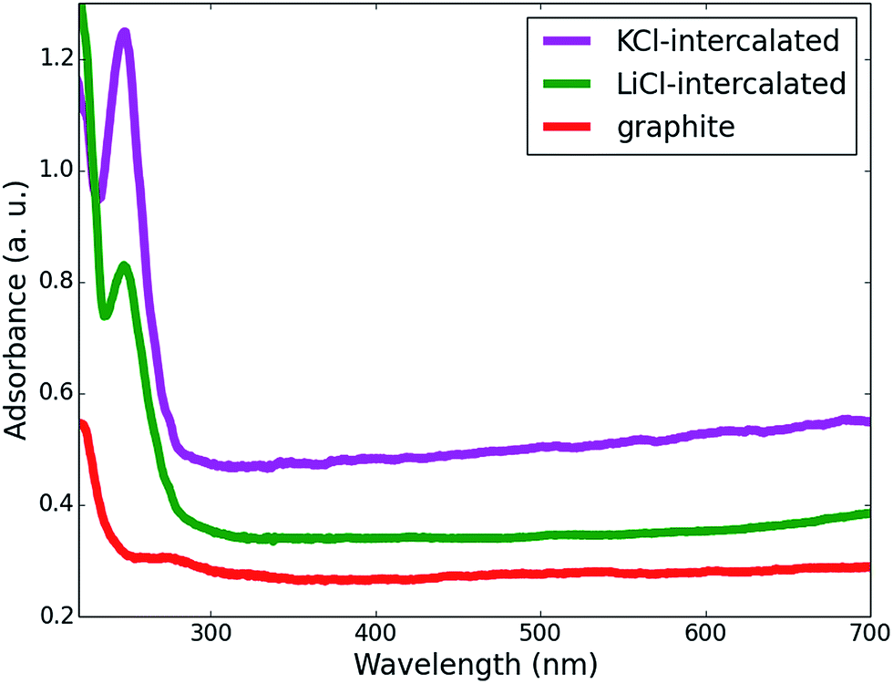 | ||
| Fig. 1 UV-vis absorption spectra of graphene-sheet dispersed in EtOH prepared from pristine, LiCl-intercalated and KCl-intercalated graphite. | ||
In order to further confirm the morphological features of the as-prepared graphene, TEM and HRTEM analyses were carried out and the results are shown in Fig. 2. The sample was prepared by dropping the clear upper solution obtained after centrifugation on the TEM grid. Transparent graphene nanosheets can be clearly seen in Fig. 2a and thinner graphene flakes are stacked together and exhibit a fold form. The HRTEM image in Fig. 2b demonstrates that the edge of the as-exfoliated graphene is composed of a few layers. The hexagonal electron diffraction pattern (Fig. 2b insert) of the TEM image indicates that the as-made graphene is highly crystalline.
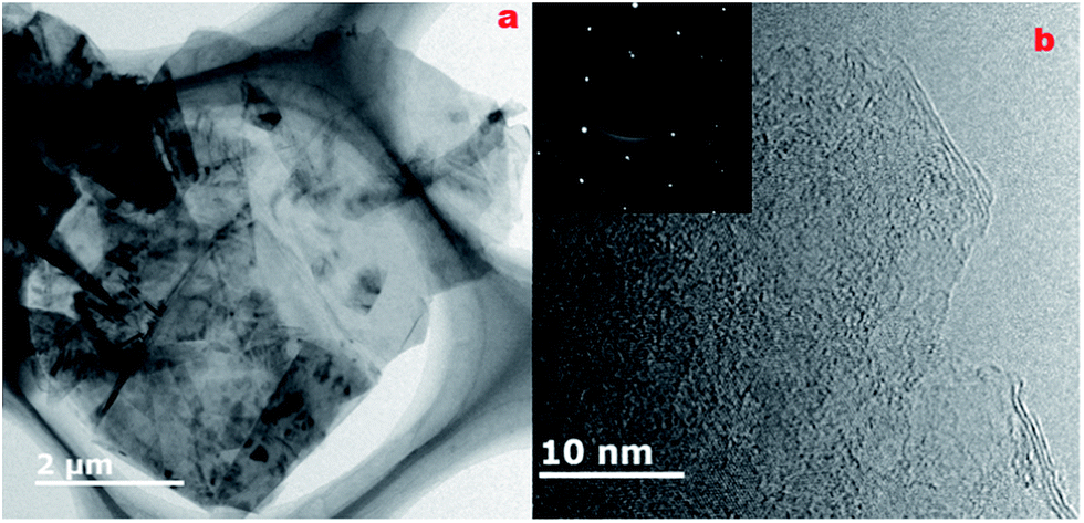 | ||
| Fig. 2 (a) TEM and (b) HRTEM images of graphene sheets obtained by LiCl-intercalation; the inset image is its electron diffraction pattern. | ||
The morphologies of the LiCl-intercalated and KCl-intercalated graphite sheets were further examined using SEM. Both the LiCl-intercalated (Fig. 3a) and KCl-intercalated graphite sheets (Fig. 3b) exhibit fine angles, and the fine-grained texture formed by the adjacent graphene is clearly visible. Moreover, some graphite fragments can be observed on the surface of the intercalated graphite samples. This seems to suggest that the interlayer spacing of the intercalated graphite is enlarged, which has also been concluded from the XRD results.
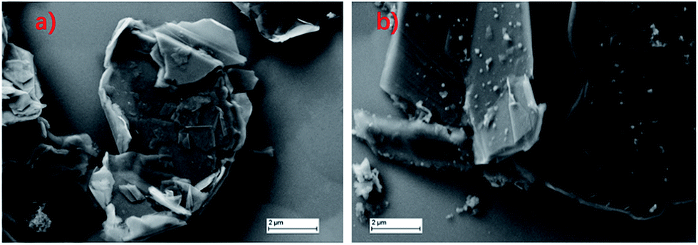 | ||
| Fig. 3 SEM image of (a) LiCl-intercalated and (b) KCl-intercalated graphite. | ||
X-ray diffraction (XRD) analysis is a powerful tool to detect structural relaxation during ion intercalation and can provide insight into the role of intercalators in exfoliation at the atomic level. The XRD patterns of pristine, LiCl-intercalated and KCl-intercalated graphite are shown in Fig. 4. For the three samples, two diffraction peaks can be observed at 26.6° and 55.0°. The peak located at 26.6° corresponds to the (002) plane and the peak at 55.0° can be assigned to the (004) plane. The (002) interplanar spacing is the distance between the neighboring layers in graphite. For both LiCl-intercalated and KCl-intercalated graphite, shifts towards lower angles were observed for the (002) peaks, suggesting an increased interlayer spacing and weakened π–π stacking interaction. For KCl-intercalated graphite, the significantly broadened (002) peak indicates structural disorder within the layers, which further weakens the π–π stacking interaction by pushing some carbon atoms out of the plane. This structural disorder may arise from the large ionic radius of K+.
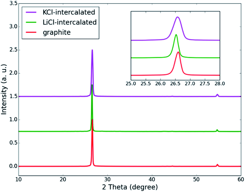 | ||
| Fig. 4 XRD patterns of inorganic salt-intercalated graphite obtained via KCl and LiCl intercalation. The inset image shows the shift of the (002) peak. | ||
Taking the structures of LiC8 and KC8 as examples, our DFT calculations (Fig. 5) indicate that when Li is inserted between the graphite layers, the distance between two layers slightly increases by 0.37 Å and this value is 1.30 Å for K. Hence, the local out-of-plane disorder induced by K intercalation is more significant than that of Li and the broadened (002) peak can be understood.
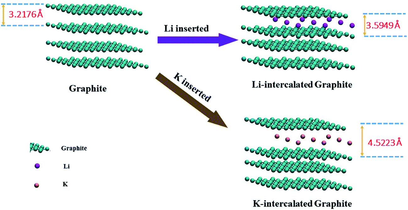 | ||
| Fig. 5 The change in the interlayer spacing of K- and Li-intercalated graphite obtained using DFT calculation. | ||
The C 1s XPS spectra of pristine, LiCl-intercalated and KCl-intercalated graphite are displayed in Fig. 6. The peak at the binding energy of about 285.0 eV corresponds to the sp2 carbon atoms. The peak located at 286.0 eV is related to C–O bonds.30 The low intensities of the peaks at 286.0 eV correspond to oxygen content values of 2.86%, 10.95% and 12.01%, in the graphite precursor, LiCl-intercalated graphite and KCl-intercalated graphite, respectively. These results are similar to the data reported in other publications31,32 and indicate that the oxidation of the prepared graphene sheets is very slight. Another peak in the binding energy range of 282.4–282.6 eV can be assigned to C–Li or C–K bonds.33 This peak confirms the role of Li and K ions in graphite exfoliation. The fact that the intensity of the peak attributed to C–K is much higher than that of C–Li may arise from the lower energy barrier for later K insertion, because the interlayer spacing is increased. As is well known, oxygen-containing functional groups in graphene sheets can relocalize the π-conjugated electrons by introducing sp3 carbon atoms, further compromising the electrical and thermal conductivity of graphene. Hence, superior electrical and thermal conductivity can be expected for graphene sheets produced via the preparation procedure with LiCl or KCl.
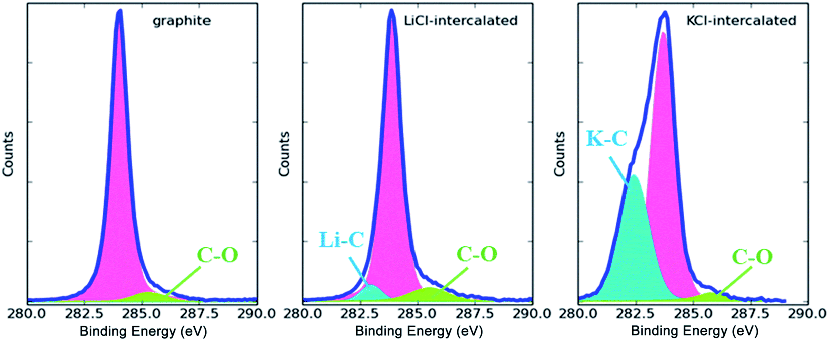 | ||
| Fig. 6 XPS spectra of pristine, LiCl-intercalated and KCl-intercalated graphite. | ||
Raman spectroscopy has been widely used in the structural investigation of carbon allotropes. In particular, it has been used to identify defects and ordered/disordered structures of graphene nanosheets, because it is a fast and non-destructive technique that provides direct insight into the electron–phonon interaction. Fig. 7 shows the Raman spectroscopy of the product powders in the range of 1000–300 cm−1. For graphene, typical features in the Raman spectra are the G peak located at ∼1580 cm−1 and the 2D peak at ∼2700 cm−1, which are assigned to the in-plane vibrations of sp2 carbon atoms and second-order zone boundary phonons, respectively. The D peak at 1336 cm−1 is stimulated by first-order zone boundary phonons, which result from the presence of defects or edge effects of graphene. For the products of LiCl and KCl intercalation, an increased intensity of the D peak is obvious, while the D peak is very weak for graphite. The ID/IG ratio is very small, which indicates few structural defects.34 In addition, compared with graphite, the band of the 2D peaks at 2680 cm−1 is symmetrical and its shoulder is disappeared, suggesting a transformation from the structure of pristine graphite to that of intercalated graphite. Raman spectroscopy allows for the monitoring of graphene.35 The shape of the 2D peak varies with the number of layers in the graphene flakes; a single narrow and sharp peak suggests a monolayer, a band with four component peaks indicates a bilayer, a broadened band is obtained for less than five layers, and finally, a graphite-type band with two component peaks indicates more than five layers. For more than five layers, the Raman spectrum becomes hardly distinguishable from that of bulk graphite.18 Compared to graphite, the slightly broader 2D peak observed in Fig. 7 for LiCl-intercalated graphite and KCl-intercalated graphite indicates the presence of graphene flakes of a few layers in both graphene samples. The position and shape of the 2D peak of the LiCl-intercalated graphite are similar to those of the KCl-intercalated graphite, suggesting that different ions only slightly affect the layer number of the as-prepared graphene sheets.
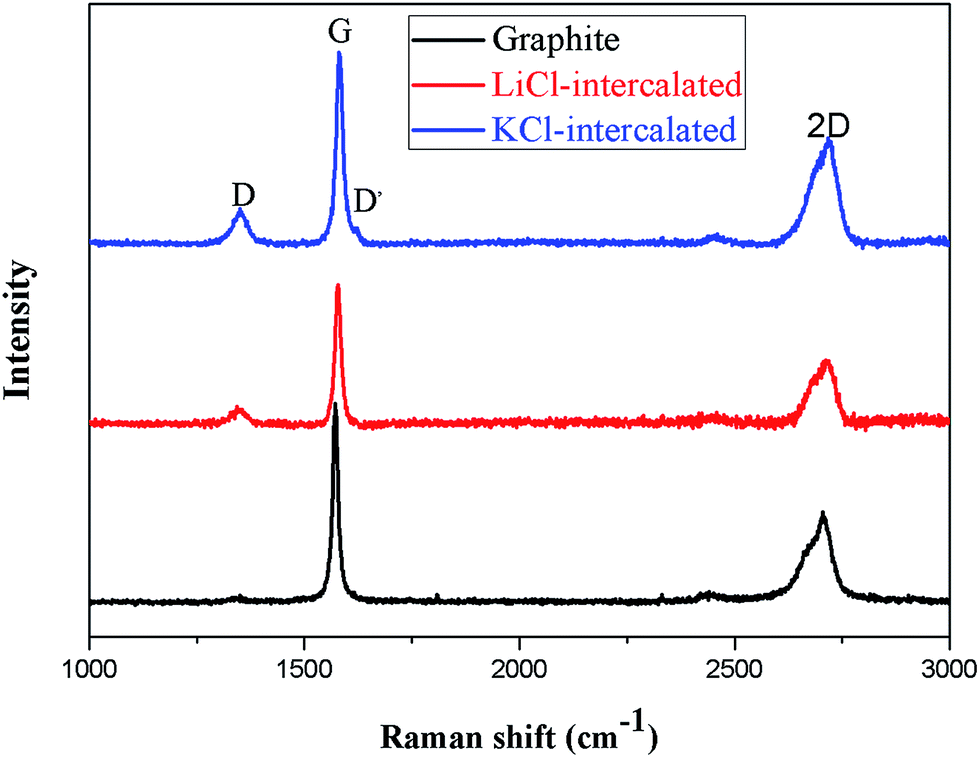 | ||
| Fig. 7 Raman spectra of inorganic salt-intercalated graphite obtained by KCl and LiCl intercalation. | ||
3.2 Effect of anions on the exfoliation efficiency
The exfoliation efficiencies of LiCl and Li2SO4 were then compared, to further elucidate the role of anions in the exfoliation process. To our surprise, the exfoliation efficiency was not invariant to the anion species. As Fig. 8a shows, Li2SO4 exhibited superior exfoliation efficiency compared to LiCl, and the yield of the thin graphene exfoliated by Li2SO4 was almost two times of that using LiCl. Although most previous research has focused on the role of cations such as Li+ in exfoliation, these results suggest that the anion also greatly contributes to the exfoliation process. Commonly, for Li-intercalated graphite, LiC6 represents the phase with the maximum amount of Li insertion into the graphite,36 so the amount of Li ions in the graphite is excessive in both the Li2SO4-intercalated and LiCl-intercalated systems in our experiments. Hence, the influence of the concentration of Li+ can be neglected. The microstructure of the synthesized graphene from Li2SO4 intercalation as presented in the TEM image (Fig. 8b) is close to that of LiCl-intercalated graphene.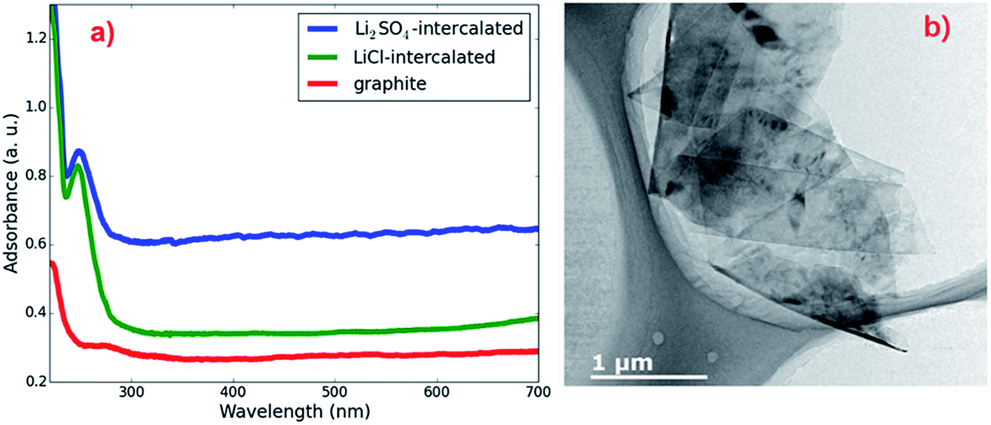 | ||
| Fig. 8 (a) UV-vis absorption spectra of graphene sheets obtained by Li2SO4 and LiCl intercalation dispersed in EtOH; (b) TEM image of graphene sheet obtained by Li2SO4 intercalation. | ||
In order to gain a better understanding of the effects of anion intercalation, we performed XRD measurements, and the results are shown in Fig. 9. The (002) peak of the product prepared with Li2SO4 is shifted to lower angles than that of the product prepared with LiCl, and a new diffraction peak emerges at 18°, corresponding to an interlayer distance of 4.94 Å. This result is close to the interlayer distance of SO42−-intercalated graphite, obtained via DFT calculations (Fig. 10). Therefore, the new diffraction peak may be attributed to the co-intercalation of both anions and cations into the graphite, which has previously been observed in graphite and a ternary KCl–NaCl–ZnCl2 eutectic salt system.16
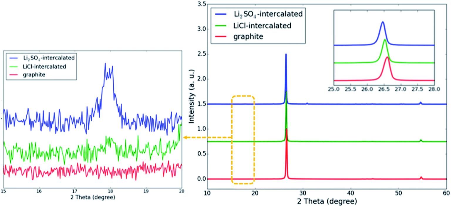 | ||
| Fig. 9 XRD patterns of inorganic salt-intercalated graphite obtained by Li2SO4 and LiCl intercalation. The inset image shows the shift of the (002) peak and the left image shows the diffraction peaks near 18°. | ||
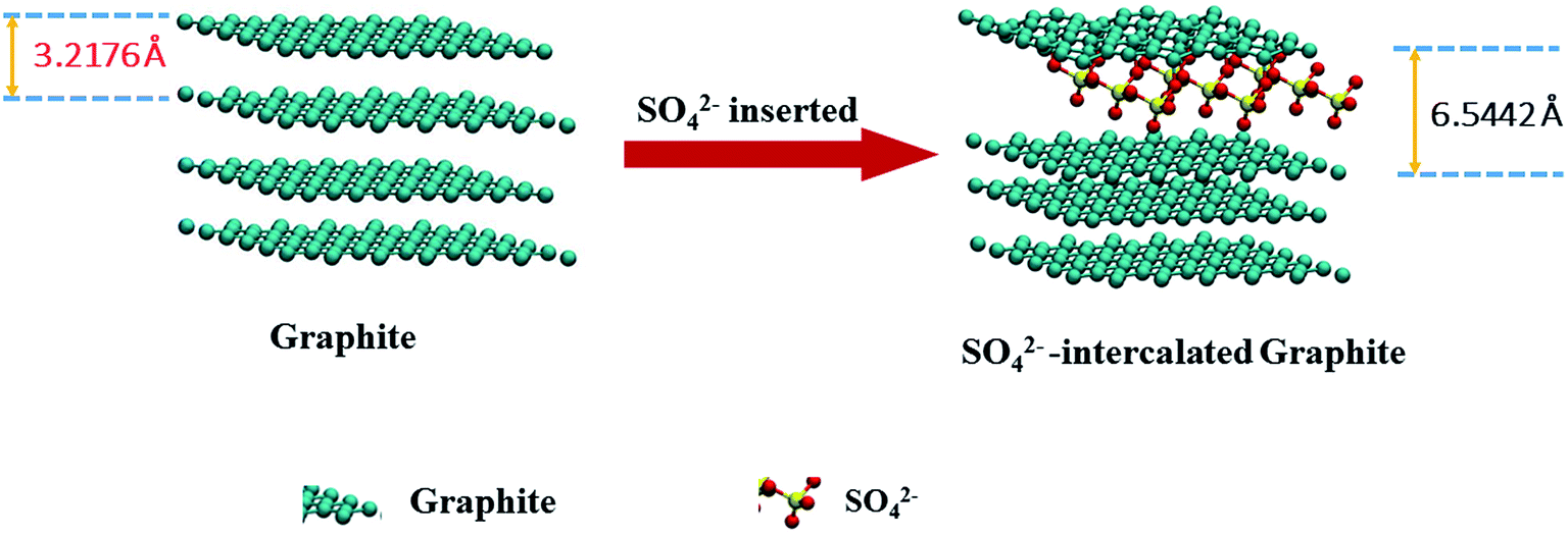 | ||
| Fig. 10 The change in the layer spacing of SO42−-intercalated graphite obtained by DFT calculations. | ||
The C 1s XPS spectra of pristine, LiCl-intercalated and Li2SO4-intercalated graphite are displayed in Fig. 11. Similar to the LiCl-intercalated graphite, the Li2SO4-intercalated graphite presents a low intensity peak at 286.0 eV, indicating a small degree of oxidation of the prepared graphene sheets. Meanwhile, the intensity of the C–Li peak for the Li2SO4-intercalated graphite in the binding energy range of 282.4–282.6 eV is closer to the sp2 carbon binding energy than that of the LiCl-intercalated graphite. This could result from the intercalation of SO4 further expanding the interlayer spacing, which weakens the interaction between the graphite sheets and Li+ ions. Since the radius of SO42− is much larger than that of Cl−, the interlayer distance of graphite is significantly larger, allowing more Li+ ions to insert themselves between the graphite layers.
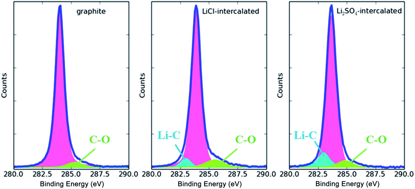 | ||
| Fig. 11 XPS spectra of pristine, LiCl-intercalated and Li2SO4-intercalated graphite. | ||
3.3 Roles of cations and anions in salt-intercalation exfoliation
On the basis of previous analysis, we propose the following mechanism for co-intercalation–exfoliation, as shown in Fig. 12. (i) The polarizable π electrons between the graphene layers of the graphite induce the aggregation of cations at the edges of the graphite, and then form the well-known [graphite anion−]Li+. (ii) Anions insert themselves into the interlayer spaces and expand the spacings between the graphite layers, thereby opening a channel for continuous ion insertion. The negative charge of the anions can be partially shielded by the cations, which decreases the energy barrier of anion insertion. (iii) More cations insert themselves within the graphite layer and form expanded graphite. (iv) The weakly bonded graphite layers are then separated by ultrasonication. Since the radius of Li2SO4 is much larger than that of LiCl, the interlayer distance at the edge is significantly larger, allowing more Li+ ions to become inserted into the graphite layers.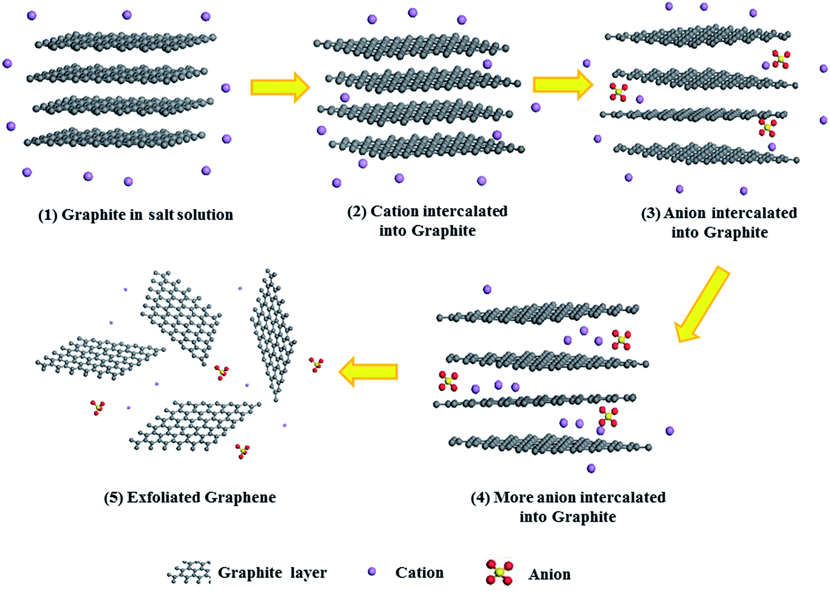 | ||
| Fig. 12 Schematic illustration of the mechanism of co-intercalation–exfoliation. | ||
To further confirm the above hypothesis, we devised contrast tests for the Li2SO4-intercalated graphite before and after ultrasonication. The EDS analysis and TEM images of the product before and after ultrasonication are shown in Fig. 13. For the product without ultrasonication (Fig. 13a), a peak for the main element C, a slight S signal peak and an O signal peak can be found, indicating that the anions are indeed intercalated into the graphite. In contrast, there are only two elements, C and Si, in the final powder after ultrasonication, as captured by EDS (Fig. 13b). Moreover, the TEM image of the sample after ultrasonication shows apparently overlapping sheets with significant wrinkles at the edges compared to the image of the sample before ultrasonication. These wrinkles may be attributed to the graphite layers becoming separated from one another in the ultrasonication process and then some SO42− ions inserted in the interlayers of the graphite becoming exposed and washed away by water. These observations support our hypothesis, and further research into the mechanism of the co-intercalation–exfoliation is in progress.
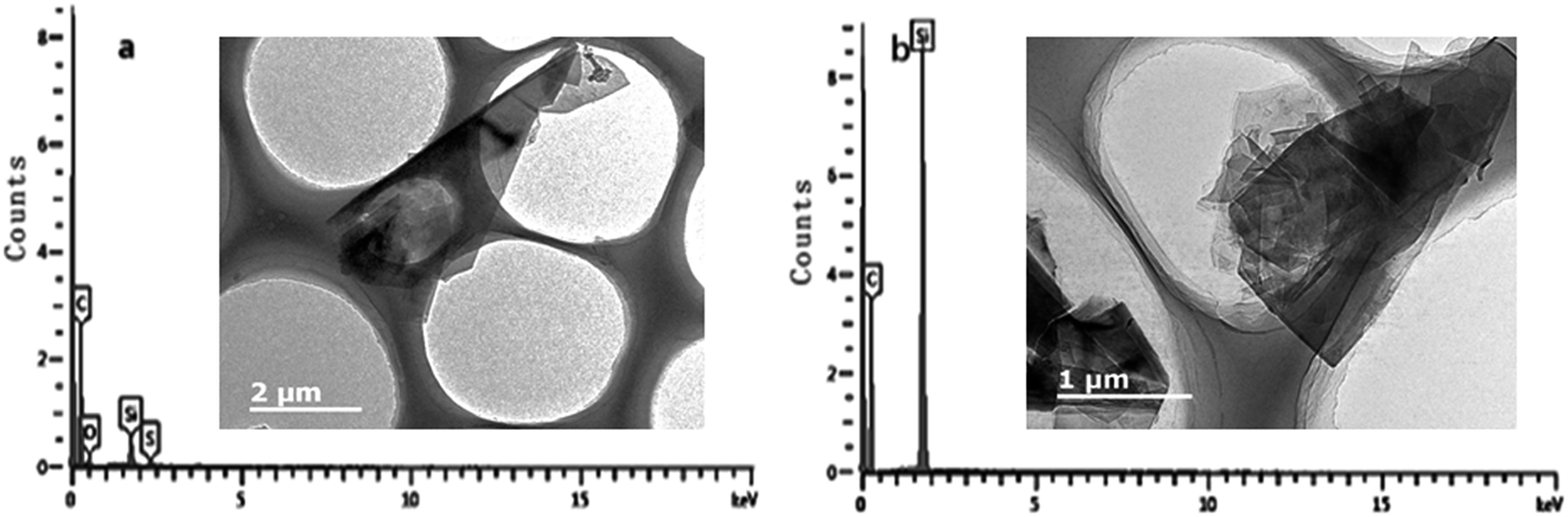 | ||
| Fig. 13 EDS analysis and TEM images of Li2SO4-intercalated graphite (a) before and (b) after ultrasonication. | ||
4 Conclusion
In summary, we present a comprehensive study to understand the contribution of cations and anions in the exfoliation of graphite into intercalated graphene for the improvement of graphene yields. Compared to LiCl, both KCl and Li2SO4 can significantly enhance the exfoliation yields of graphene. Our results suggest that while the cation is a critical factor for improving the exfoliation yields, anions such as Cl− and SO42− also contribute to the exfoliation of graphene. We propose that co-intercalation with both anions and cations occurs during the intercalation process in the solution of inorganic salts. By optimizing the species and concentration of both cations and anions, the yield of graphene can be improved. This work opens an avenue for the facile and effective exfoliation of graphite into graphene by inorganic salt intercalation, and offers a new scientific perspective for science and technology.Conflicts of interest
There are no conflicts to declare.Acknowledgements
This study was supported by grants from the National Natural Science Foundation of China (Grant No. 11604341 and 21403246). We thank valuable guidance from Prof. Lin Mingzhang. We further thank the great help from other members of FDS Team in this research.References
- A. M. Brockway and J. Schrier, Noble Gas Separation using PG-ESX(X= 1, 2, 3) Nanoporous Two-Dimensional Polymers, J. Phys. Chem. C, 2013, 117, 393–402 CAS.
- Y. Tao, et al., Tunable hydrogen separation in porous graphene membrane: first-principle and molecular dynamic simulation, ACS Appl. Mater. Interfaces, 2014, 6, 8048–8058 CAS.
- A. W. Hauser, J. Schrier and P. Schwerdtfeger, Helium Tunneling through Nitrogen-Functionalized Graphene Pores: Pressure- and Temperature-Driven Approaches to Isotope Separation, J. Phys. Chem. C, 2012, 116, 10819–10827 CAS.
- C. Sun, et al., Mechanisms of molecular permeation through nanoporous graphene membranes, Langmuir, 2014, 30, 675–682 CrossRef CAS PubMed.
- Y. Wang and S. K. Bhatia, Quantum Effect-Mediated Hydrogen Isotope Mixture Separation in Slit Pore Nanoporous Materials, J. Phys. Chem. C, 2009, 113, 14953–14962 CAS.
- Y. Wu, et al., Identification of safety gaps for fusion demonstration reactors, Nat. Energy, 2016, 1 Search PubMed.
- Y. Wu and F. D. S. Team, Conceptual design activities of FDS series fusion power plants in China, Fusion Eng. Des., 2006, 81, 2713–2718 CrossRef CAS.
- Y. Wu and F. D. S. Team, CAD-based interface programs for fusion neutron transport simulation, Fusion Eng. Des., 2009, 84, 1987–1992 CrossRef CAS.
- Y. Wu, CLEAR-S: an integrated non-nuclear test facility for China lead-based research reactor, Int. J. Energy Res., 2016, 40, 1951–1956 CrossRef.
- H. Zheng, et al., Photon Dose Calculation Method Based on Monte Carlo Finite-Size Pencil Beam Model in Accurate Radiotherapy, Comm. Comput. Phys., 2013, 14, 1415–1422 CrossRef.
- W. Yican, Development of High Intensity D-T fusion NEutron Generator (HINEG), Proceedings of the Reactor Physics Asia (RPHA15) Conference 16-18, 2015 Search PubMed.
- M. Lv, Y. Wang, Q. Wang, T. Wang and Y. Liang, Structural changes and tribological performance of thermosetting polyimide induced by proton and electron irradiation, Radiat. Phys. Chem., 2015, 107, 171–177 CrossRef CAS.
- G. Yang, B.-J. Kim, K. Kim, J. W. Han and J. Kim, Energy and dose dependence of proton-irradiation damage in graphene, RSC Adv., 2015, 5, 31861–31865 RSC.
- Z. Bai, L. Zhang and L. Liu, Bombarding Graphene with Oxygen Ions: Combining Effects of Incident Angle and Ion Energy To Control Defect Generation, J. Phys. Chem. C, 2015, 119, 26793–26802 CAS.
- K. R. Paton, et al., Scalable production of large quantities of defect-free few-layer graphene by shear exfoliation in liquids, Nat. Mater., 2014, 13, 624–630 CrossRef CAS PubMed.
- K. H. Park, et al., Exfoliation of non-oxidized graphene flakes for scalable conductive film, Nano Lett., 2012, 12, 2871–2876 CrossRef CAS PubMed.
- M. V. Bracamonte, G. I. Lacconi, S. E. Urreta and L. E. F. F. Torres, On the Nature of Defects in Liquid-Phase Exfoliated Graphene, J. Phys. Chem. C, 2014, 118, 15455–15459 CAS.
- E. C. Ou, et al., High concentration and stable few-layer graphene dispersions prepared by the exfoliation of graphite in different organic solvents, RSC Adv., 2013, 3, 9490–9499 RSC.
- K. Manna, H. N. Huang, W. T. Li, Y. H. Ho and W. H. Chiang, Toward Understanding the Efficient Exfoliation of Layered Materials by Water-Assisted Cosolvent Liquid-Phase Exfoliation, Chem. Mater., 2016, 28, 7586–7593 CrossRef CAS.
- M. Lotya, et al., Liquid Phase Production of Graphene by Exfoliation of Graphite in Surfactant/Water Solutions, J. Am. Chem. Soc., 2009, 131, 3611–3620 CrossRef CAS PubMed.
- E. C. Vermisoglou, et al., Effect of hydrothermal reaction time and alkaline conditions on the electrochemical properties of reduced graphene oxide, Appl. Surf. Sci., 2015, 358, 100–109 CrossRef CAS.
- H. Zhang, T. Kuila, N. H. Kim, D. S. Yu and J. H. Lee, Simultaneous reduction, exfoliation, and nitrogen doping of graphene oxide via a hydrothermal reaction for energy storage electrode materials, Carbon, 2014, 69, 66–78 CrossRef CAS.
- L. Niu, et al., Salt-assisted direct exfoliation of graphite into high-quality, large-size, few-layer graphene sheets, Nanoscale, 2013, 5, 7202–7208 RSC.
- X. R. Liu, et al., Simple, green and high-yield production of single- or few-layer graphene by hydrothermal exfoliation of graphite, Nanoscale, 2014, 6, 4598–4603 RSC.
- X. Gonze, et al., ABINIT: first-principles approach to material and nanosystem properties, Comput. Phys. Commun., 2009, 180, 2582–2615 CrossRef CAS.
- M. Torrent, F. Jollet, F. Bottin, G. Zérah and X. Gonze, Implementation of the projector augmented-wave method in the ABINIT code: application to the study of iron under pressure, Comput. Mater. Sci., 2008, 42, 337–351 CrossRef CAS.
- S. Grimme, Semiempirical GGA-type density functional constructed with a long-range dispersion correction, J. Comput. Chem., 2006, 27, 1787–1799 CrossRef CAS PubMed.
- S. R. Dhakate, et al., An approach to produce single and double layer graphene from re-exfoliation of expanded graphite, Carbon, 2011, 49, 1946–1954 CrossRef CAS.
- M. Lotya, P. J. King, U. Khan, S. De and J. N. Coleman, High-Concentration, Surfactant-Stabilized Graphene Dispersions, ACS Nano, 2010, 4, 3155–3162 CrossRef CAS PubMed.
- K. Parvez, et al., Exfoliation of Graphite into Graphene in Aqueous Solutions of Inorganic Salts, J. Am. Chem. Soc., 2014, 136, 6083–6091 CrossRef CAS PubMed.
- A. M. Dimiev, G. Ceriotti, A. Metzger, N. D. Kim and J. M. Tour, Chemical Mass Production of Graphene Nanoplatelets in Approximately 100% Yield, ACS Nano, 2016, 10, 274–279 CrossRef CAS PubMed.
- M.-Y. Cheng, et al., Defect-free graphene metal oxide composites: formed by lithium mediated exfoliation of graphite, J. Mater. Chem., 2012, 22, 14722 RSC.
- Y. S. Hu, W. H. Kong, L. Hong, X. J. Huang and L. Q. Chen, Experimental and theoretical studies on reduction mechanism of vinyl ethylene carbonate on graphite anode for lithium ion batteries, Electrochem. Commun., 2004, 6, 126–131 CrossRef CAS.
- J. Chen, et al., Eco-friendly exfoliation of graphite into pristine graphene with little defect by a facile physical treatment, Appl. Phys. Lett., 2016, 108, 073105 CrossRef.
- W. J. Zhao, P. H. Tan, J. Liu and A. C. Ferrari, Intercalation of Few-Layer Graphite Flakes with FeCl3: Raman Determination of Fermi Level, Layer by Layer Decoupling, and Stability, J. Am. Chem. Soc., 2011, 133, 5941–5946 CrossRef CAS PubMed.
- G. Yoon, et al., Factors Affecting the Exfoliation of Graphite Intercalation Compounds for Graphene Synthesis, Chem. Mater., 2015, 27, 2067–2073 CrossRef CAS.
| This journal is © The Royal Society of Chemistry 2017 |