
 Open Access Article
 This Open Access Article is licensed under a
 Creative Commons Attribution 3.0 Unported Licence
Identification of the functional states of human vitamin K epoxide reductase from molecular dynamics simulations†‡
N. Chatronabc,
B. Chalmonda,
A. Trouvéa,
E. Benoîtb,
H. Caruelc,
V. Lattardb and
L. Tchertanov *a
*a
aCentre de Mathématiques et de Leurs Applications (CMLA), ENS Cachan, CNRS, Université Paris-Saclay, 61 avenue du Président Wilson, Cachan, 94235 France. E-mail: Luba.Tchertanov@ens-cachan.fr
bUSC 1233 INRA-Vetagro Sup, Veterinary School of Lyon, Marcy l'Etoile, France
cLiphatech, Bonnel, 47480 Pont du Casse, France
First published on 9th November 2017
Abstract
In mammalians, the enzymatic activity of vitamin K epoxide reductase (VKORC1) requires a protein conformational reorganisation that includes several transient enzymatic states involving a dynamic electron transfer. Regarding the structurally non-characterised human enzyme (hVKORC1), this process remains poorly explained and the different redox states of the enzyme generated by its biochemical transformation are unknown. Here, we report a 3D model of the fully reduced hVKORC1 at the atomistic level. By exploring this model through molecular dynamics (MD) simulations, we established the most probable intermediate states of the enzyme which were used for generation of the putative functionally-related enzymatic states. Enzymatic functionality of each state was assigned by probing their recognition properties with respect to vitamin K in its quinone and hydroxyquinone forms. Two states were identified as contributing to the two-step vitamin K transformation. The state highly selective for native vitamin K was further validated through analyses of its free energy of binding with vitamin K agonists (VKAs) that showed a high correlation with the experimental inhibiting constants.
Introduction
The mammalian vitamin K epoxide reductase (VKOR) VKORC1 is an endoplasmic reticulum (ER)-resident transmembrane protein involved in γ-carboxylation of glutamate residues of vitamin K-dependent proteins (PVKD). These proteins include blood clotting factors, matrix Gla protein and osteocalcin,1,2 and their enzymatic modification by VKORC1 is mandatory for essential physiological processes, such as coagulation,3 calcium homeostasis,4 energy metabolism,5 signal transduction and cell development.6,7 Specifically, VKORC1 converts the inactive form of vitamin K (vitamin K 2,3-epoxide) into vitamin K quinone and its reduced active form, vitamin K hydroquinone, the cofactor used for PVKD activation.1 The active site of VKORC1 contains a highly conserved CXXC motif8 that is essential for vitamin K quinone reduction.9 Two other cysteine amino acids, which participate in the electron exchange between the active site and a thioredoxin-like domain in bacterial species, are also conserved among species.10–12 The function of the latter cysteine residues in human VKORC1 remain controversial1,13,14 as the regulation of human enzyme activity differs from that of the bacterial enzyme, i.e. in the absence of a thioredoxin domain, hVKORC1 should use an external partner as a redox source.15Deregulation of the catalytic activity of hVKORC1, usually prompted by naturally occurring mutations, is responsible for different diseases including haemorrhaging disorders16 and arterial calcifications,17 whereas hVKORC1 polymorphisms are associated with resistance to vitamin K agonists (VKAs).18 Analysis of hVKORC1 structure–function relationships may provide a better understanding of its activation process and guide therapeutic strategies aimed at neutralizing enzyme dysfunctions.
As for many membrane proteins, VKOR structure remains very much a matter of debate. In the absence of hVKORC1 structural data, homology models were built from the crystallographic structure of Synechococcus sp. VKOR, a bacterial homolog of hVKORC1, in which the 280-amino acid sequence is organised into five transmembrane helices.10 This homology modelling has produced divergent topologies of the human protein, including a three-helix (3-H TM) a four-helix (4-H TM) and a five-helix (5-H TM) transmembrane model12,19–22 (Fig. 1). The 3-H TM model suggested by Stafford23,24 was improved by adding a charged residue distribution that affects TM orientation.25,26 The 4-H TM topology model generated by a recent biophysical study of VKORC1 and VKORC1L1 could be more physiologically relevant27 but establishing a reliable 3D model for hVKORC1 remains a challenge.
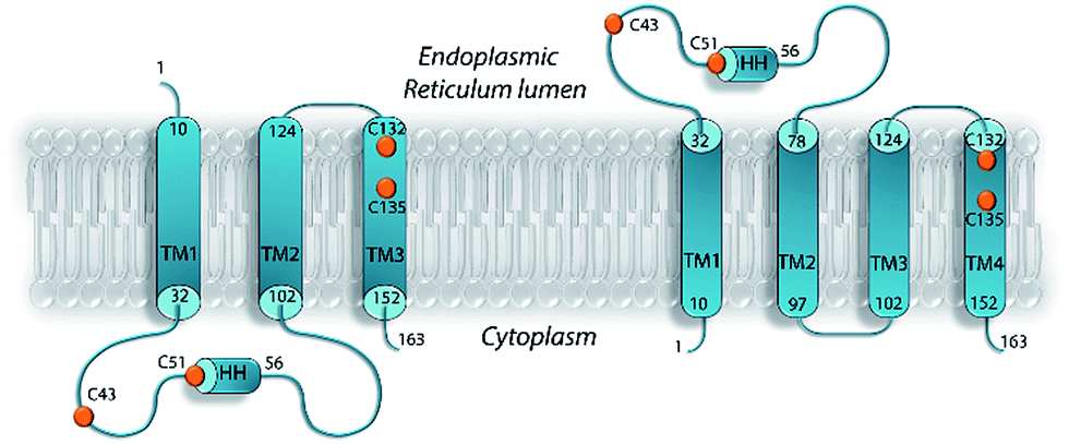 | ||
| Fig. 1 Proposed topological models for VKOR. A three-helix transmembrane domain (3-H TMD) model with the N- and C-terminus located in the endoplasmic reticulum (ER) lumen and in the cytoplasm respectively (left). A four-helix transmembrane domain (4-H TMD) model with the N- and C-terminus located in the cytoplasm (right). Positions of the first and the last residues of the transmembrane (TM) helices and a short helix (HH) are shown. The conserved cysteine residues are denoted as orange balls. | ||
VKORC1 contributes to vitamin K transformation within the endoplasmic reticulum.28 It has been proposed that the redox partner of VKORC1 is a protein disulphide isomerase or thioredoxin-like protein, namely TMX, TMX4, and ERp18.9,29
A thiol/disulphide-based mechanism of vitamin K reduction proposed in ref. 8 and 30 postulates a sequence of chemical transformations involving the four cysteine residues of hVKORC1 – C43, C51, C132 and C135 – in particular, their reversible protonation/deprotonation of the sulphur atom (S) followed by forming/breaking of the disulphide bonds. These events are associated with hVKORC1 conformational reorganisation leading to transition from the passive (inactive) to the active states through transient intermediate enzymatic products.31 There are different combinations of protonation states for each cysteine residue coded for the nine distinct forms of VKORC1 – the extreme sets in which all cysteine residues are either deprotonated and linked by S–S bonds (oxidised form) or protonated (SH, reduced form) and the intermediate sets formed by combination of protonated and deprotonated cysteine residues. The endoplasmic reticulum location of VKORC1 suggests that once integrated into a membrane, the protein folding is stabilized by the two disulphide bonds, maintaining a fully folded (inactive) enzyme state. This enzyme state can be activated by external factors, such as binding of thioredoxin(s) initiating a reduction in hVKORC1 protein by thiol–disulphide exchange.9,32 Because of electron-transfer, the covalently linked cysteine residues of hVKORC1 switch to enzymatically active items, specifying intermediate (or metastable) states of the protein that become capable of transforming vitamin K. In accordance with a multi-step procedure for vitamin K modification, the biochemical and structural data show four or five intermediate states.11 Such an abundance of enzymatic transformations and the approximate assignment of the cysteine residue's states/functions indicate that modelling of the activation process and definition of the enzymatically active and biologically relevant hVKORC1 states is a bona fide enigma.
Considering the questions addressed on VKORC1 topology and on the assignment of the biologically consistent states, the theoretical description of hVKORC1 structural features should be (i) maximally disassociated from the uncertain/contradictory literature data, and (ii) based on methods yielding pragmatic and sine qua non releases.
In the present work, we have designed an hVKORC1 3D atomistic model to be used in MD simulation. To avoid a priori assignment of the sulphur bridge, we performed this simulation on a fully reduced form of enzyme. We do not state that the protein dynamics of this model, which are described using the classical mechanics approximation, will reproduce exactly the functional states of protein that are mandatorily associated with proton exchange and disulphide bridge formation/disruption. However, the MD conformations generated over multiple short simulations (100 ns) and the extended trajectories (the microsecond time scale), could be sufficient to predict the functionally relevant enzymatic states of hVKORC1. We distinguished four conformations viewed as plausible mimics of the intermediate states of enzyme. The predicted conformations were further optimised and subjected to MD simulations producing the functionally related enzymatic states, which were assigned by probing their recognition properties with respect to vitamin K in its quinone and hydroxyquinone forms. Two states were identified as contributing to two-steps vitamin K transformation. The state highly selective for native vitamin K was further validated through analyses of its free energy of binding with the vitamin K agonists (VKAs) that showed a high correlation with the experimental inhibiting effect.
Results and discussion
1. Modelling of hVKORC1
After searching the Protein Data Bank (PDB),33 we retrieved four reports describing the structure of VKOR from Synechococcus sp. (bVKOR, 283 amino acids, aas) (ESI, Table S1‡). The alignment of the sequences revealed a bVKOR segment (13–181 aas) having the best identity/homology (25/36%) with hVKORC1 (163 aas) (ESI, Fig. S2A‡). Since the homology is weak between sequences, we first used a set of independent bioinformatics methods for prediction of the secondary structure composition in proteins. These methods are designed on distinct concepts and algorithms and they correctly forecasted all structural elements of the experimentally characterized bVKOR (4NV5, resolution of 2.80 Å)11 (ESI, Fig. S1‡), thus validating the accuracy of the prediction methods. These methods were applied to predict the secondary structure of the target sequence, hVKORC1. Apparently, the overall structure of hVKORC1 consisted of one short and four elongated helixes (ESI, Fig. S2B‡). Secondly, we built a homology model for hVKORC1 using 4NV5 as a template. The homology model denotes the four-helix structure of the VKORC1 transmembrane domain, which is consistent with the predicted secondary structure composition and the experimental data supporting the 4-H TM topology.27 In our model, the first and the second transmembrane helices, respectively TM1 and TM2, are linked by the extended loop (L½) with a small horizontal helix (HH) in the middle, while the other helices are linked by the short loops in a head-to-tail manner, as TM2–TM3 and TM3–TM4 (Fig. 2A). The four-helix compacted transmembrane bundle is stabilized by (i) the coil-coiled dimeric structural motif composed of a HxxHCxC heptad repeat (hydrophobic residues H, charged residues C and random residues x) – 24LYALHVK30 and 94LGCLRTR100 – from TM1 and TM2 respectively, and (ii) the mutual hydrophobic interactions between four TMs (ESI, Fig. S3‡).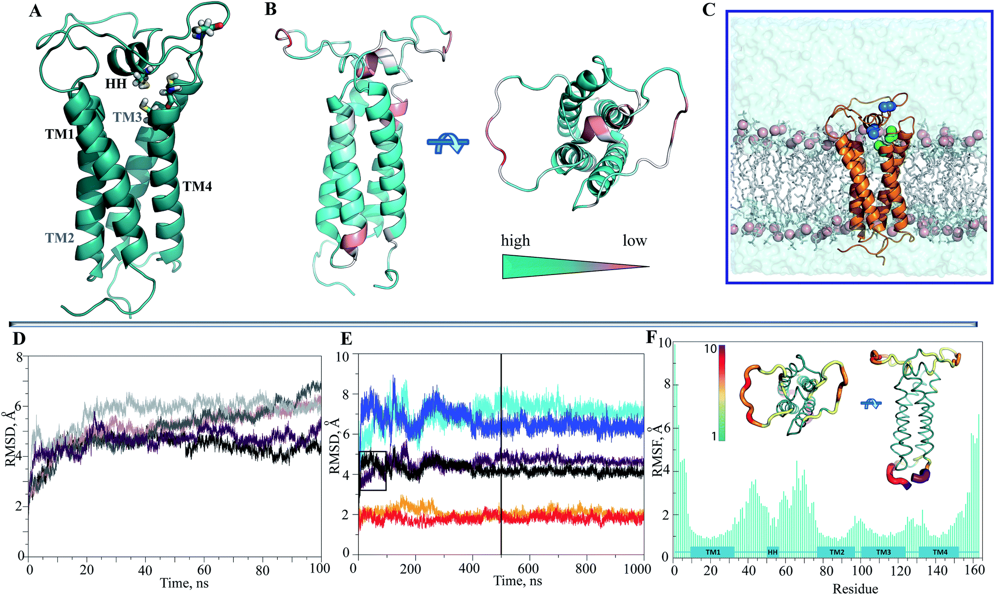 | ||
| Fig. 2 Modelling and molecular dynamics simulations of hVKORC1. (A) The homology model of hVKORC1 is pictured as cartoon. The cysteine residues (C43, C51, C132 and C135) are shown in sticks coloured by the atoms type. (B) The per domain quality estimation of the hVKORC1 model that shown in two orthogonal projections. The quality of prediction is specified by color ranged from deep teal (high) to light salmon (low). (C) The simulated system is composed of the hVKORC1 model embedded into membrane and completed with water molecules. (D) The RMSDs from the initial coordinates (t = 0 ns) are computed on the Cα atoms of 100 ns MD trajectories (replicas 1–5 are differed by color). (E) The RMSDs from the initial coordinates (t = 0 ns) computed from two extended trajectories, of 500 μs (1 → 1′ and 3 → 3′, delimited by vertical line) and of 1 μs (1 → 1′′ and 3 → 3′′) on the all Cα atoms (brown/black), on the Cα atoms from the TM helices (orange/red) and on the Cα atoms from the extended luminal loop (cyan/blue). A small rectangle borders the 100 ns part of trajectories 1′ and 3′. (F) The RMSFs are computed on the Cα atoms over the 1 μs simulation (3′′) of hVKORC1. In inserts: the average conformation of hVKORC1 (3′′) is presented as tubes in two perpendicular projections. The tube size is proportional to the by-residue atomic fluctuations computed on the Cα atoms. The high fluctuation regions are specified by color ranged from green, the most rigid, to violet, the most mobile. | ||
The two cysteine residues, C43 and C51, are positioned at L½ and the two others, C132 and C135, at helix TM4. The feasibility of the prediction was encouraging, with the per domain estimation indicating a low quality secondary structure prediction for only several residues at the extremity of TM1 and TM3, for the HH, and for the distal segments of L½ (Fig. 2B).
Assignment of the transmembrane fraction in template and target was achieved by the two-prediction consensus associated with the secondary structure and the membrane topology contents respectively (ESI, Fig. S1 and S2B‡).
In accordance with the 4-H TM topology, our in silico prediction showed that the extended loop L½ and the short TM3–TM4 linker were located in ER lumen, whereas the N- and C-terminals together with the loop linker TM2–TM3 were positioned in the cytoplasm. The transmembrane topology assignment was used for an appropriate embedding of the hVKORC1 structural model in phospholipid bilayers, mimicking the ER membrane (Fig. 2C). Instead of phosphatidylethanolamine (PE) used in a bilayer composition in the MD simulation of hVKORC1,34 we generated the membrane with phosphatidylcholine (PC) molecules, as this is most appropriate for reticulum content.35
2. Structure and dynamics of hVKORC1
Since the simulated system, which is composed of the hVKORC1 homology model embedded in the membrane and completed with water molecules (Fig. 2C), may be too large to expect statistical convergence within a 100 ns MD simulation, we first performed five repeats (replicas 1–5) to probe the conformational variability of protein using the random starting velocities. Such probing may be pertinent when scanning a large conformation diversity of the fully reduced model. The root mean square deviations (RMSDs), computed using the positions of Cα atoms relative to the initial structure (t = 0 ns) showed the poor stability of this model within the simulation time (Fig. 2D). Two randomly chosen MD simulations (1 and 3) were prolonged to 500 ns (1′ and 3′) and further to 1μs (1′′ and 3′′). It was supposed that the extended simulations of hVKORC1 would allow either the equilibrated state(s) of protein to be reached or the conformations mimicking the functional states of enzyme to be produced. In these extended trajectories (1′′/3′′) the RMSDs (all Cα atoms, brown/black) showed large variations (4.5–6.5 Å) until ∼300–400 ns and further, demonstrating their fine stability (Fig. 2E). The largest contribution to the ample RMSDs was gathered by the extended luminal loop, L½, (blue/cyan) while the transmembrane helices (orange/red) had no considerable impact.To quantify the extent to which the homology model represents a realistic and stable structure in the timescales studied, we assessed the protein secondary structure with DSSP.36 Analysis performed on the individual MD trajectories of different lengths and on the merged data, indicated well-defined, long-lived transmembrane helices (Fig. 3A, ESI, Fig. S4A‡), supporting a correctness of the four-helix model. However, L½ demonstrated some structural variability over MD simulations. In particular, the fold of sequence R33–N77 (L½) was interpreted as the two loops linked either by a short α-helix (70–90%) or by a 310-helix/turn. The tiny turns and the short α- or 310-helices observed in the L½ and in the loops linking each pair of transmembrane helices were only partially stable.
 | ||
| Fig. 3 Structural features of hVKORC1. (A) The secondary structure evolution over MD simulations (all trajectories were merged). The α-helix, 310 helix, β-bridge, turn and loop are shown in red, orange, light-green, blue and cyan, respectively, and referred to the predicted helices (top). (B–C) Drift of helices, monitored over the extended (1 μs) simulations, is shown for 3′′. Two centroids, assigned on the last four residues at the top and at the bottom of each helix, were defined. A sole centroid for HH was assign on seven residues. Coordinates of each centroid were computed for each MD simulation time step and presented as the lines connecting the two TM centroids, in 3D space (B) and as the points projected on the x–y plane (C) coloured from blue (t = 0) to cyan (t = 1 μs) for the top of TM helices; from black (t = 0) to green (t = 1 μs) for the bottom; and from red (t = 0) to yellow (t = 1 μs) for HH. (D) Drift of the two L½ sub-fragments, R33–S50 and S57–N77, respect to HH was monitored for each simulation separately. Centroids were defined on HH and on each sub-fragment of the L½, subdivided into the proximal and distal parts in respect to HH as shown at the left. Coordinates of each centroid (five in total) were computed for each MD simulation time and presented as the lines connecting the two sequent centroids projected on the y–z plane, and presented as the color-coded lines or points superimposed into the hVKORC1 conformation at t = 0 (grey). (E) Hydrophobic/hydrophilic (red/cyan) content of L½ is shown on the sequence and on the structure. | ||
The root mean square fluctuations (RMSFs) computed for each residue from either the short (100 ns) or the prolonged (1 μs) simulations were comparable (ESI, Fig. S5‡). As expected, the highest fluctuations were principally observed for the residues of L½, of the N- and C-terminals and also, but essentially less so, of the loop-linkers, TM2–TM3 and TM3–TM4 (Fig. 2F).
To identify the source of the high RMSD values, we first analysed the structural drift of the folded TM and HH helices, and secondly that of the coiled L½. Surprisingly, within the same TM helix the movement of residues at the extremities of the TM helices, either close to the cytoplasm or to the ER lumen, was not equivalent during the simulations. This difference was in the path direction and the absolute value of displacement, resulting in a bent TMs drift (Fig. 3B and C; ESI, Fig. S4B‡).
The small HH of L½ is well conserved over the simulations and to a first approximation may be viewed as the internally stable structural element in the studied time-scale that is able to move with respect to the membrane helices rather than change a structure fold per se. The HH is displaced largely in a plane defined by the apexes of the TMs and along their axes (Fig. 3C). This ample alteration of HH position may simultaneously depend on the TM helices drift and on the large movements of the two coiled sub-fragments of L½, encompassing R33–S50 and S57–N77 respectively (Fig. 3E). The drift of these sub-fragments showed that the luminal part of hVKORC1 was running from a ‘cave-like’ to a ‘plateau-like’ configuration (Fig. 3D), showing that the relative positions of the two loop sub-fragments and of the HH and TM helices varied from proximal to distant.
The slow motions of hVKORC1 were characterized by the principal component analysis (PCA). Ten PCA modes were sufficient to describe ∼80–90% of the total fluctuations of the hVKORC1 backbone (Fig. 4A). The two first modes illustrate large atomic motions of the residues from the loop L½, the loop-linkers TM2–TM3 and TM3–TM4, and the N- and C-terminals. Nevertheless, the direction of the motions and their amplitudes presented by each corresponding mode are not equivalent in distinct trajectories (Fig. 4B).
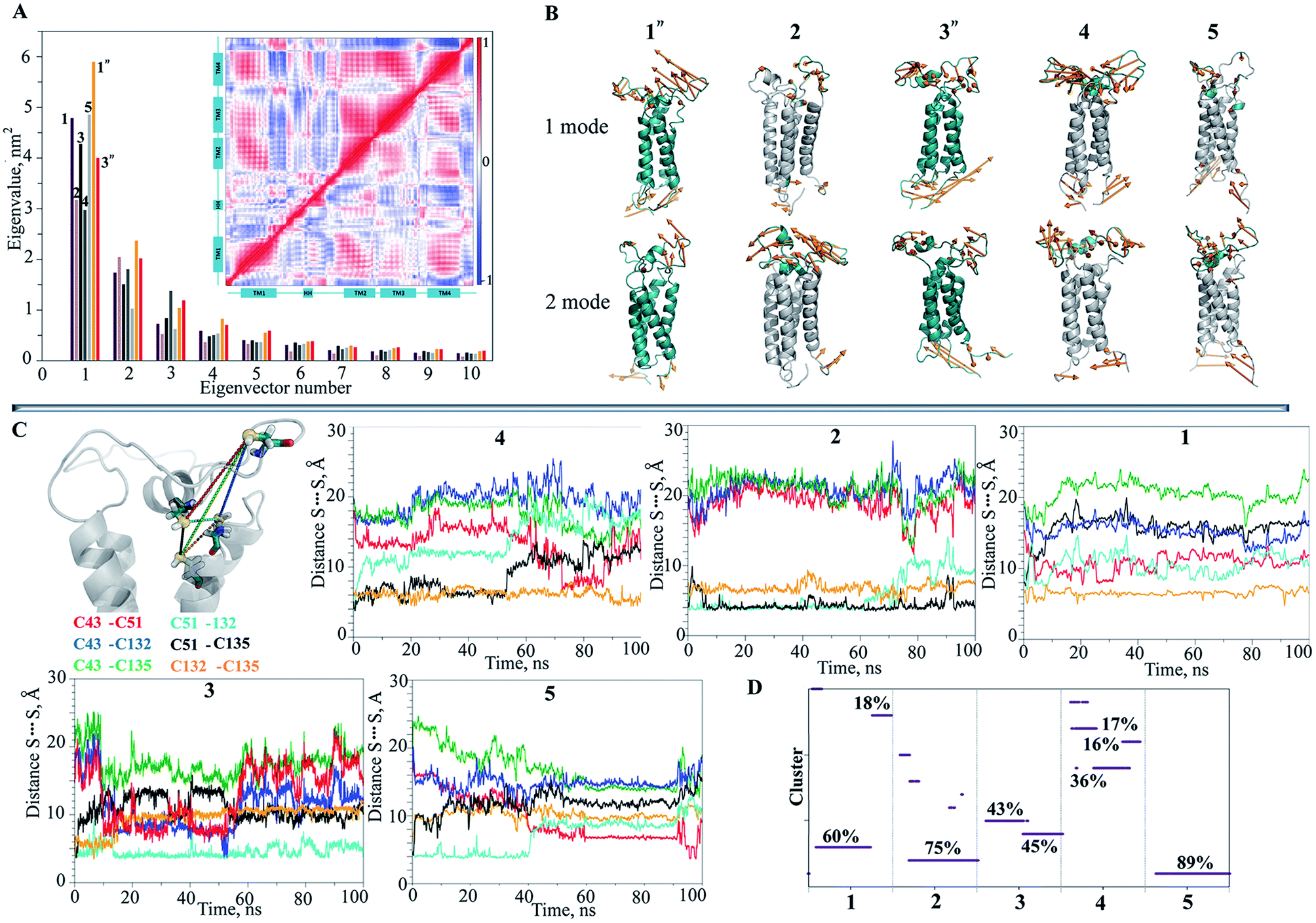 | ||
| Fig. 4 Structural and dynamical features of hVKORC1. (A) Principal component analysis (PCA) was performed on the backbone atoms from the 100 ns (brown, dark salmon, black, grey dark and grey light bar graph for replicas 1–5 respectively) and the 1 μs MD trajectories (orange and red for 1′′ and 3′′ respectively). In insert: inter-residue cross-correlations maps resulting from PCA of two extended (1 μs) trajectories, 1′′ (the upper half-matrix) and 3′′ (the lower half-matrix). Correlated and anti-correlated motions between atom pairs are presented as color gradient of red (positive) and blue (negative) respectively. (B) Slow motions (modes 1 and 2, computed for each trajectory) are illustrated as orange arrows on the cartoon representation of protein coloured in deep teal for extended simulations (1′′ and 3′′) and in grey for short simulations (2, 4 and 5) in which the most moving fragments are highlighted in deep teal. (C) Interatomic S⋯S distances between the sulphur atoms from cysteine residues in hVKORC1 (left) were monitored over each short (100 ns) MD simulations. The curves characterizing the S⋯S distances between different pairs of cysteine residues are differentiated by color: C43–C51 is in red, C43–C132 is in blue, C43–C135 is in green, C51–C132 is in turquoise, C51–C135 is in black and C132–C135 is in orange as showed on the first image, together with the axes labels. (D) The clusters of conformations defined with cutoff of 2.0 Å and their population (in %) calculated for each short (100 ns) simulation. | ||
Similar to the RMSF values, the PCA denotes the greatest mobility of L½ with respect to the other domains. The PCA cross-correlation patterns of the short and extended trajectories are generally comparable and demonstrate the highly coupled motions between distant structural subunits (insert in Fig. 4A; ESI, Fig. S6‡). The strong correlation of the TM helices motion, apparently, is associated with their drift, while the large dynamic flexibility of the extra-membrane loop L½ exposed to an aqueous environment demonstrates a rich conformational variability in the hVKORC1 model.
Since the distance between sulphur atoms (S⋯S) in the cysteine residues is the indicative metric that distinguishes conformations between favouring or frustrating the formation of a disulphide bond, S–S, the six distances between each pair of sulphur atoms were monitored over each MD trajectory (Fig. 4C). Despite the same initial structural model at t = 0, in which three S-atoms (from C51, C132 and C135) are adjacent (all interatomic S⋯S distances of 4–6 Å), and the sole S-atom (from C43) is largely distant (at 20 Å) in this S-cluster, the model evolution over the different MD trajectories was not equivalent. Each S⋯S distance is initially either short or large and then this varied significantly during the simulation with respect to the primary value. Delimiting the range of 4–6 Å as favourable for the establishment of the S–S bond, and considering an occurrence of such a contact during the simulations, we suggest that the pairs C43–C51, C51–C132, C132–135 and C51–C135 are the candidates for the S–S covalent bonding. Conversely, the systematically observed large distance between C43 and C135, and between C43 and C132, indicates a low probability of interaction between these pairs of residues. The multiple MD conformations have a short S⋯S distance between two pairs of cysteine residues simultaneously (C43–C51 and C132–C135) and this may encourage the formation of the two S–S bridges.
To focus our analysis on the protein backbone conformational changes, we decided to perform the clustering calculations. We found that (i) the MD conformations of each trajectory were grouped (cutoff of 2 Å) in one (2, 5), two (1, 3) or more (4) clusters (subsets) and (ii) the subsets are mutually exclusive (the portioning effect) (Fig. 4D), giving large conformational samples to be analyzed.
We further searched the conformational space explored by protein in the 1 μs MD simulations using an estimation of the population (density) of the conformations in the low dimensional space (the first PCA mode). The similarity matrix W (see Methods and References herein) computed from the raw conformations or after a PCA reduction, is structured into blocks, each consisting of a set of close conformations (Fig. 5A).
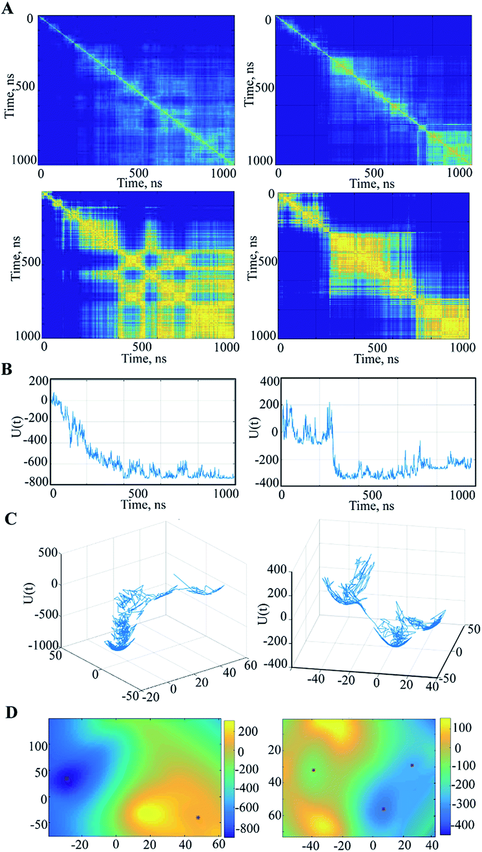 | ||
| Fig. 5 Spectral analysis of the MD simulation data. (A) Similarity matrices (pairwise distance) between all observed conformations {xi, i = 1, …, N} computed for all Cα-atoms of 1′′ and 3′′ trajectories before (top) and after the PCA (bottom), in which each vector xi was replaced by the vector ξi of a dimension 2. The color-coded distance between each vector, yellow for the similar conformations and blue for the distant. (B) The temporal evolution of the variation δU(ξi) ≐ U(ξi) − U(ξ0) with respect to the energy of the initial conformation at t = 0. (C) The trace of the trajectories of the conformations after a 2D PCA reduction on the energy surface for trajectories 1′′ and 3′′ plotted with respect to the two first PCA components. (D) The energy landscapes for the two trajectories using the spline surface representation. | ||
The different blocks are plausibly associated with metastable or intermediate states. The blocks show distinct patterns in the analysed trajectories that are partitioned (after the 200–300 ns) into the segregate blocks in 3′′ and are arranged into the extended rosette-like crowds in 1′′, which may indicate revisited conformations. Note first that the PCA dimension reduction does not really degrade the cluster patterns but results in highly contrasted similarity content. Second, for computation and display purposes, this PCA reduction can be helpful for the data analysis. Each vector xi is replaced by a vector ξi of very small dimension r by a PCA (typically, r = 2 or 3).
The local occupation density π(x) at a given scale σ is estimated as described in Methods, inducing a free energy landscape U(x) that reflects the similarity matrix composed of blocks corresponding to time intervals where the energy is relatively stable. This property is emphasized by the slow variable profiles, as shown in ESI (Fig. S7 and S8‡) for the trajectory 3′′. A slow variable is a one-dimensional function q(xi) that is related to the underlying Langevin dynamics and thus to the similarity matrix W, which gives a synthetic and simplified view of the blocks in W, as is the case in spectral clustering.37,38
For the free energy profile the temporal evolutions of energy U are plotted as curves ti → U(xi) or ti → U(ξi) depending on whether one considers PCA dimension reduction or not. However, it is interesting to represent the free energy landscape U(x) as a hypersurface parametrized using the conformation x. For visualization we use a 2D reduction to display the free energy landscape as a 2D surface in 3D as ξ → U(ξ), and display the evolution of the dynamics as a random walk in this landscape. Doing so, the trace of the path of the random walk on the energy landscape is plotted (Fig. 5C) and reveals a sampled version of the main visited basins. The energy landscape is useful for computation of the energy minima locations, as shown in Fig. 5D. In fact, these minima are extracted from a continuous smooth representation of the sampled surface, which is computed using a spline model.39
When applied to the trajectory 3′′, the energy landscape shows three well-defined and highly populated local minima that probably correspond to the metastable states of hVKORC1, and are linked by saddles connecting two neighbouring minima that describe a transition between the different states (Fig. 5C and D). The observed dynamics of these multiple-basin landscapes involves long period motions within a basin followed by fast transition to another basin, which is an event described as a ‘jumping among minima’ that has been observed in a study of molecular dynamics using other methods.40 The height of the energy barriers is proportional to the timescale that is necessary to stochastically convert between states. The energy landscape of 1′′ trajectory, with a meaningless minimum at the beginning of a simulation, is better described as a fall of leaves to the ground reaching the global minimum.
In summary, based on the prediction of secondary structure and comparative (homology) modelling we have obtained a 3D model of hVKORC1 consisting of four transmembrane helices that corresponds to the 4-H TM topology. The MD simulations of this model in the fully reduced state and integrated into a membrane were analysed with the statistical methods (RMSDs, RMSFs, PCA, cross-correlation, clustering), which gave evidence on features of the hVKORC1 dynamics that can be related to its functions. In particular, the ability of the extended luminal loop to undergo ample movements reflects the conformational plasticity of hVKORC1 enabling us to provide suitable sites for substrate recognition and binding. The binding pocket for thioredoxin proteins, which are the hVKORC1 reducers, may be constituted by numerous hydrophobic residues (60%) in the loop (Fig. 3E). The correlated movements of the transmembrane helices and the luminal loop indicate the global conformational adaptability of hVKORC1, which is relevant to the proton transfer processes followed by forming/breaking of the disulphide bonds, and consequently, to the hVKORC1 conformational reorganisation that leads to different transient enzymatic states, from inactive to active. Observing the variation in distances between the sulphur atoms from the cysteine residues indicates a great conformational variability in hVKORC1 associated with these multiple states. We selected pairs of cysteine residues viewed as candidates for establishing disulphide bonds. The stochastic MD trajectory representation by the similarity matrix, energy profile and energy surface, provided the highly populated minima that are composed of conformations showing short S⋯S contact between two pairs of cysteine residues.
The hVKORC1 conformations having a short C51–C132 contact that may mimic the active state of hVKORC1 described in the literature31 and observed in most crystallographic structures of the bacterial homologue, bVKOR. The hVKORC1 conformation showing a short S⋯S distance between the pairs of cysteine residues C132–135 is also observed in crystallographic structure 3KP9 of bVKOR.10
3. Modelling the enzymatically relevant states of hVKORC1
The hVKORC1 conformations that have a short S⋯S distance between the pairs of cysteine residues were locally modified to adjust the predicted state of hVKORC1. Specifically, the hydrogen atoms connected to at the sulphur atoms that exhibited a short S⋯S distance were removed and the S⋯S distance was constrained to 2.1 Å, which is typical for an S–S bond. The resulting models were optimised and made the subject of standard MD simulations. These models may represent four intermediate states of hVKORC1 – the state stabilised with two pairs of covalently bonded sulphur atoms from cysteine residues C43–C51 and C132–C135 (MI), and the states stabilized by a lone S–S bond linking either C132–C135 (MII) or C51–C132 (MIII) or C43–C51 (MIV) (Fig. 6A).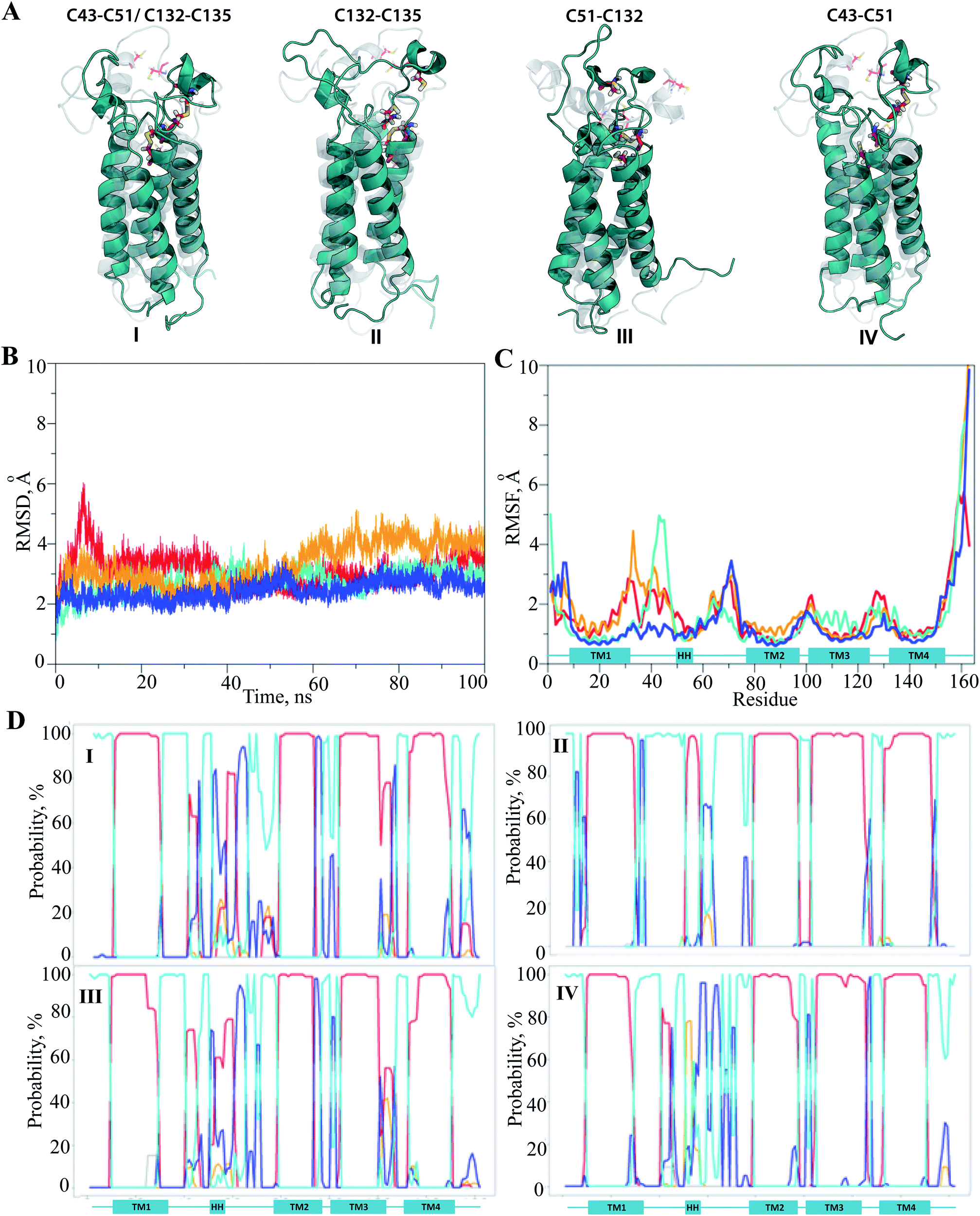 | ||
| Fig. 6 Molecular dynamics simulations of the hVKORC1 models MI–MIV. (A) The optimized and refined by MD simulations structural models (deep teal) with S–S of 2.1 Å are superposed with conformations identified from MD simulations of fully protonated model (grey). For each model, numerated by Roman, the pairs of cysteine residues forming S–S bond are denoted at the top. Protein is depicted as cartoon, the cysteine residues (C43, C51, C132 and C135) are shown as sticks coloured by the atoms type. (B) The RMSDs from the initial coordinates (t = 0 ns) are computed on the Cα atoms over MD trajectories (100 ns) of MI–MIV (blue, orange, deep teal and red, respectively). (C) The RMSFs are computed on the Cα atoms over the 100 ns simulations of MI–MIV (blue, orange, deep teal and red, respectively). (D) The secondary structure evolution over MD simulations of MI–MIV. The α-helix, 310 helix, β-bridge, turn and loop are shown in red, orange, light-green, blue and cyan, respectively, and referred to the predicted helices. | ||
It was suggested that the MD trajectories of 100 ns would be sufficient to achieve the equilibrated states since the models' MI–MIV were stiffened by the one or two S–S bridges with respect to the fully-protonated initial model of hVKORC1 with four cysteine residues in reduced form (SH). The RMSDs, which were computed for the Cα atom positions relative to the initial structure (t = 0 ns), show the excellent (MI) and satisfactory stability (MII–MIV) within the simulation time (Fig. 6B). The RMSFs showed that the largest contribution to the ample fluctuations in all simulated models was gathered by the extended luminal loop, L½ and the inter-helices loops, which is similar to the fully-protonated model (Fig. 6C and 2F). However, the values of these fluctuations were considerably diminished. The lowest values of RMSFs were observed in the MD simulation of MI, where only the S57–N77 loop fluctuations up to 3.5 Å were present. In models containing a single S–S bond fluctuation values up to 5 Å were observed, varying in the order: MII > MIV > MIII > MI.
Analysis of the protein secondary structure content (DSSP)36 indicated well-defined, long-lived transmembrane helices, which was strongly conserved in all models (Fig. 6D; ESI, Fig. S9‡). In contrast, L½ demonstrated some structural variability that was similar to the fully-protonated model. Nevertheless, the overall conformational variability was diminished for each model, MI–MIV, as shown by the reduced number of clusters composed of similar conformations (within a cut-off of 2 Å). Indeed, only one highly populated cluster was observed in the conformational set of MI, MIII and MIV with populations of 76, 73 and 56%, respectively, as well as in MII where the conformations are grouped in three distinct clusters with populations of 37, 24 and 18% (ESI, Fig. S10‡).
The representative conformations extracted from each of the most populated clusters are different (i) in conformation of L-loop, (ii) in folding of HH and (iii) in position of HH relative to the TM helices. The small helix HH was observed in fragment L58–L60 in MII, while in MI–MIII, the regularly folded structure included the residues that preceded and followed this region (Fig. 7A). The most folded and compacted L-loop is detected in MI. In MIII the HH is oriented horizontally with respect to TMs that is positioned in close proximity to the transmembrane domain. In the other models the HH axis is coincident with the TMs helices, but its relative position with respect to TMs varies from proximal (in MI) to distant (in MIV).
 | ||
| Fig. 7 Representation of the hVKORC1 states and their binding properties in respect to vitamin K. (A) Pocket (in mesh) detected at each representative conformation MI–MIV (left) and (B) its volume (right). (C) The best docking poses of the cleaved vitamin K epoxide found for each representative conformation obtained from MD simulations of MI–MIV. Vitamin K epoxide with the cleaved chain in opaque is showed in right. (D) The complexes vitKEP·MIII (left) and vitK2-OH·MIV (right) equilibrated by MD simulations. (E) The per residues contribution to the binding free energy (ΔG) in vitKEP·TIII (green) and vitK2-OH·TIV (red) complexes. The labeled residues are characterized by the higher ΔG values. The protein is shown as cartoon with cysteine residues in sticks; vitamin K is shown in ball-and-sticks. | ||
The representative conformation from each of the most populated clusters was characterized with Fpocket41 in order to localize a surface pocket that could be a binding site for vitamin K. In all conformations, we found that the pocket is positioned between the TM helices in the proximity of the endoplasmic reticulum lumen, and that the pocket's volume varies from 450 Å3 (MI) to ∼530 Å3 (MIII) (Fig. 7B). It is interesting to note that during the simulations we observed the lipids being inserted into the pocket, indicating the hydrophobic nature of residues forming in the pocket's cavity.
4. Recognition of vitamin K by hVKORC1
It was supposed that the representative conformation for each identified cluster is the target (T) for the vitamin K epoxide or its degraded form, namely vitamin K hydroxyquinone (ligand, L). First, to identify the appropriate target of the native form, the vitamin K epoxide (vKEP) was docked (AutoDock42) with each target, TI–TIV. The docking of the full-length vitamin K produced mutual poses of the ligand that probably arose from high flexibility of the aliphatic chain. Since only the naphthoquinone fragment of vitamin K is functional,43 the aliphatic chain was cut at the fourth carbon atom and the cleaved vitamin K was re-docked with the targets. The number of vitamin K poses within each target was diminished, but the docking scores were much closer and were not clearly distinguishable from the L·T complexes (Table 1). Nevertheless, a visual inspection of the ligand poses with an occurrence greater than 10% permits us to distinguish between the apt and irrelevant L·T complexes.| State | Form | |||
|---|---|---|---|---|
| vitKEP | vitK2-OH | vitK3-OH | vitKQU | |
|
|
|
|
|
| TI | 2 [58/42] −7.0/−6.8 | 7[3/54/22/4/9/1/7] −7.2/−6.9 | 3[57/5/38] −7.3/−6.8 | 5[60/17/1/19/3] −7.0/−7.0/−6.9 |
| TII | 5[42/25/4/16/13] −6.9/−6.9/−6.7/−6.6 | 9[57/25/1/1/3/2/2/2/7] −6.7/−6.4 | 7[11/21/2/5/2/3/56] −6.7/−6.7/−5.7 | 6[52/20/4/1/14/9] −6.8/−6.7/−6.5 |
| TIII | 2[88/12] −6.2/−7.7 | 5[50/27/10/12/1] −6.3/−6.2/−6.1/−6.0 | 3[33/61/6] −6.7/−6.3 | 3[54/42/4] −6.5/−6.2 |
| TIV | 4[74/14/10/2] −7.4/−7.2/−7.2 | 5[9/82/7/1/1] −7.6 | 5[41/44/8/6/1] −7.7/−7.4 | 6[48/36/12/1/2/1] −8.2/−7.6/−7.4 |
In TI, which has two S–S bridges, the two alternative poses of the substrate in the binding pocket gave a comparable score and population. Similarly, in TII the substrate is localized in four clusters composed of the randomly oriented molecule. In contrast, the poses of vKEP in TIII form the unique highly populated cluster (88%), which qualifies the vKEP·TIII complex as very plausible (Fig. 7C). The visual inspection of the docking solution showed that vitamin K is localized in the proximity of the protonated residues C43 and C135 of TIII with the epoxide fragment oriented towards these residues. The vitamin K docking with TIV showed the most populated poses of a substrate in a position remote from the protonated cysteine residues.
Consequently, from these docking trials we have defined TIII as the most probable target of a vitamin K epoxide. This target may represent the active (or activated) state of hVRORC1 that recognizes specifically vKEP and performs the first step in vitamin K transformation, which is the opening of the epoxide cycle of vitamin K by a cleavage in the C–O bond.
To better study the enzymatic steps leading to vitamin K transformation, we probed a vitamin K hydroxyquinone (vK2-OH and vK3-OH) docking with the targets TIII and TIV. The docking results indicated that (i) vK2-OH formed the more populated docking poses with all inspected modified targets with respect to vK3-OH; (ii) the best pose of vK2-OH was obtained by the docking with TIV. The vitamin K quinone (vitKQ) was randomly positioned in the pocket forming four principle clusters.
5. The vitamin K affinity to hVKORC1
Since the complexes vKEP·TIII and vK2-OH·TIV were potentially plausible, as was found from the docking trials (scores, poses and their population), we studied their stability and compared the free binding energy that maintains these complexes. First, we reconstituted the full-length vitamin K by a consequent growing of its aliphatic chain cleaved prior to the docking. The two complexes with the reconstituted vitamin K were further studied using MD simulations.The RMSDs calculated on the backbone atoms from TIII and TIV showed that their values were reduced relative to the free targets and were stable during the 100 ns MD simulations (ESI, Fig. S11A‡). The pattern of the RMSFs generally corresponds to that in free targets (ESI, Fig. S11B‡). Analysis of the vKEP·TIII conformations at the end of the simulations (80–100 ns) revealed that vitamin K is stably bound to the hydrophobic groove of the target formed with residues of TMs and HH (Fig. 7D; ESI, PDB Files S1, S1-1, S1-2‡). The naphtoquinone fragment of vitamin K in vKEP·TIII is located in the proximity of C135, with a distance of 4.0 Å between the carbon atom of the epoxide fragment of vitamin K and the sulphur atom of C135, which corresponds well to the suggested association between the vitamin K epoxide and VKORC1.43 The aliphatic chain of vitamin K protrudes into the membrane in the direction perpendicular to the naphthoquinone plane, between TM2 and TM3. In the vK2-OH·TIV complex the partially transformed molecule is still bound in the binding site, but is displaced from the position observed in vKEP·TIII.
The binding free energy, ΔG, estimated by the MM/PBSA approach44 differs considerably, with values of −52.3 and −44.1 kcal mol−1 for vKEP·TIII and vK2-OH·TIV respectively (Table 2 and Fig. 8B). The decomposition of ΔG for the different terms contributing to the binding affinity of vitamin K helps to identify the primary forces driving such a binding. The van-der-Waals energy (ΔGvdw) shows more variation (−53.5 kcal mol−1 for vKEP·TIII and −47.6 kcal mol−1 for vK2-OH·TIV) than for the other terms, and appears to be the principal force contributing to the difference in the final binding energy values (ΔGbind) in the studied complexes (Table 2). The electrostatic energy (ΔGel) and the solvation energy, represented by polar (ΔGpol) and non-polar (ΔGnon-pol) parts, show only minor variations between two complexes.
| Ligand·target | ΔGelect | ΔGvdw | ΔGpol | ΔGnon-pol | ΔGbind |
|---|---|---|---|---|---|
| vKEP·TII | −1.1 ± 0.3 | −53.5 ± 5.2 | −8.1 ± 0.8 | −5.7 ± 0.4 | −52.3 ± 5.2 |
| vK2-OH·TIV | −1.0 ± 0.4 | −47.6 ± 3.6 | −9.9 ± 2.1 | −5.4 ± 0.4 | −44.1 ± 3.1 |
| A·TIII | −0.9 ± 0.4 | −42.5 ± 2.9 | −10.4 ± 1.3 | −4.5 ± 0.2 | −37.6 ± 2.9 |
| D·TIII | −0.5 ± 0.2 | −46.9 ± 2.7 | −9.3 ± 2.3 | −5.2 ± 0.3 | −43.2 ± 3.4 |
| P·TIII | −0.7 ± 0.3 | −34.3 ± 3.4 | −6.3 ± 1.0 | −3.9 ± 0.2 | −32.5 ± 3.7 |
| W·TIII | −0.7 ± 0.4 | −34.6 ± 2.1 | −9.5 ± 1.6 | −4.1 ± 0.2 | −29.9 ± 2.6 |
 | ||
| Fig. 8 The ligands binding to hVKORC1. (A) Vitamin K epoxide stabilized by van-der-Waals interactions with hydrophobic residues of TIII. The protein is viewed as cartoon with cysteine residues in sticks; vitamin K is shown in ball-and-sticks. (B) The binding free energy (ΔG) calculated by MM/PBSA in complexes formed by vitamin K ant its targets, vKEP·TIII and vK2-OH·TIV, and in complexes inhibitor·TIII. (C) The correlation between the computed ΔG and the measured inhibiting constants, Ki. Each inhibitor is denoted by color: acenocoumarol, A (violet), difenacoum, D (orange), phenprocoumon, P (purple) and warfarin, W (cyan). | ||
To identify the key molecular determinants responsible for the binding of vitamin K to the targets, we calculated the per residue energy contribution of all the protein residues to the overall binding energy. In both complexes, vKEP·TIII and vK2-OH·TIV, the free energy binding value is only influenced by the hydrophobic residues demonstrating a favourable contribution to the vitamin K affinity (Fig. 7E and 8A). The largest contribution to vitamin K epoxide affinity was from F55 interacting with the naphthoquinone fragment within the binding site and by F86 interfacing the aliphatic chain protruding into the membrane. In the vK2-OH·TIV complex the vitamin K hydroxyquinone is mainly bound by the highly increased interaction with F86, while the interaction with F55 is reduced with respect to vKEP·TIII. The other residues, L22, A26, F87, V112, A115, G116, L120 and V134, contribute positively to the substrate affinity in both forms, though their impact is different. The role of F55 as a key residue binding either the substrate or warfarin was recently reported.45
This simple analysis of the free binding energy has shown that (i) the hydrophobic interactions are key to vitamin K recognition by hVKORC1, (ii) TIII provides the most favourable hydrophobic interactions, which are greater than the target TIV and (iii) F55 contributes most to affinity of the vitamin K epoxide in the binding pocket of TIII, while F86 preserves the binding of vitamin K hydroxyquinone to TIV.
6. Models-based concept of the hVKORC1 enzymatic cycle
By considering the distinct recognition properties of the generated models of hVKORC1 with respect to vitamin K in its different forms, we attempted to assemble these models in a logical scheme that presents a plausible enzymatic cycle of the vitamin K transformation. Initially, in the absence of external factors hVKORC1 is apparently folded in the fully deprotonated state and is stabilized by two S–S covalent bonds. This state, represented by the TI model that non-selectively recognized vitamin K and that might correspond to the inactive state of hVKORC1. Upcoming protons (delivered by a thioredoxin through the inter-protein proton exchange) perturb the hVKORC1 by initiating a break of S–S bridge between the L-loop cysteine residues, C43 and C51, and their protonation producing the state described by model TII. Further proton-transfer (intra-protein) promotes a reduction in the cysteine residues, C132 and C135, which is accompanied by conformational adaptation of hVKORC1 to a state favourable to vitamin K binding in the pocket in close proximity to the activated cysteine residues (Fig. 7C). Such a step is shown by the target TIII demonstrating a highly selective binding with the vitamin K epoxide. This step yields the hydroxyquinone form of vitamin K, with the opened epoxy group that is still bound to the binding site of the newly transformed hVKORC1 and target TIV that is ready to attack the vitamin K again. The targets TIII and TIV may represent two active states of VKORC1, which successively transform the vitamin K through the epoxide opening (TIII, active-1) followed by the OH group removal (TIV, active-2). The fully transformed vitamin K is not retained by the enzyme, which is further transformed to the initial oxidase state.Recapitulating our results, we postulated two plausible sketches of the hVKORC1 enzymatic process, which were conceived entirely from the predicted models and their ability to bind vitamin K. The first hypothesis suggested a direct involvement of thioredoxin in the reversible covalent interaction of vitamin K with hVKORC1 (Fig. 9C), and this is derived from the enzymatic mechanism specified for the bacterial homolog bVKOR.11 According to the second hypothesis, the thioredoxin protein initiates the reduction in hVKORC1 as a proton donor (Fig. 9B). This simple and comprehensive sketch may reflect the most rational and probably the most credible catalytic cycle of the hVKORC1 enzymatic mechanism.
 | ||
| Fig. 9 Role of the metastable states of hVKORC1 in the hVKORC1 enzymatic process. (A) Vitamin K epoxide (left) and vitamin K hydroxyquinone (right) stabilized by van-der-Waals interactions with hydrophobic residues of TIII and TIV respectively. (B) The single-protein-based reduction cycle and (C) the two-proteins-based reduction process of vitamin K. hVKORC1, vitamin K and thioredoxin are sketched in blue, violet and green respectively. The hVKORC1 states predicted from MD simulations are countered in salmon. The proton path and the point of vitamin K insert are showed by red and black arrows, respectively. | ||
7. Inhibitor affinity to hVKORC1
Since target TIII is highly selective for native vitamin K binding, we postulated that this state is a target of the vitamin K agonists (VKAs). The well-known VKAs, namely acenocoumarol (A), difenacoum (D), phenprocoumon (P) and warfarin (W) were docked with TIII. As the AVKs do not contain the aliphatic chain, the docking trials produced a highly populated cluster, which demonstrated the unique pose of each inhibitor. Each inhibitor is localized in the binding pocket of the target that takes the position of the naphthoquinone fragment of the vitamin K (Fig. 10B). Each inhibitor·target complex was further studied using MD simulations (100 ns). Similar to vKEP·TIII, the RMSDs of hVKORC1 in each inhibitor·target complex were stable during the MD simulations (ESI, Fig. S11‡) and each inhibitor was stably bound to the hydrophobic groove of the target (Fig. 10D; ESI, PDB Files S2, S2-1, S2-2‡). The binding free energy (ΔG) was estimated using the MM/PBSA method and gave values of −37.6 ± 2.9, −43.2 ± 3.4, −32.5 ± 3.7 and −29.9 ± 2.6 kcal for A, D, P and W respectively (Fig. 8B and Table 2), which are significantly smaller than for the vitamin K epoxide. The decomposition of the binding free energy for the different terms contributing to inhibitor affinity showed that the primary forces driving inhibitor binding are also the van-der-Waals interactions. The calculated per residue energy contribution of all target residues indicated that the free energy binding value is only influenced by the hydrophobic residues, which demonstrate a favourable contribution to the inhibitor affinity, principally from F55 and V134, similarly to the natural substrate binding (Fig. 10C). F55 was previously reported as a key residue for warfarin binding.45 | ||
| Fig. 10 Inhibitors binding to hVKORC1. (A) Structural formula of acenocoumarol (A), difenacoum (D), phenprocoumon (P) and varfarin (W). (B) Docking poses of inhibitors in the binding pocket of hVKORC1. The protein is viewed as cartoon with cysteine residues in sticks; each inhibitor is shown in ball-and-sticks. (C) The per residues contribution to the binding energy (ΔG) of TIII to acenocoumarol (1st column), difenacoum (2nd column), phenprocoumon (3rd column) and warfarin (4th column). (D) AVKs, (A, D, P and W) stabilized by van-der-Waals interactions with hydrophobic residues of TIII. Protein is depicted as cartoon; inhibitors are showed in ball-and-sticks with their surface; the hydrophobic residues are drawing in sticks with a color coded for the strength of interaction, from a strong (in dark) to a weak (white), and the contribution to the binding free energy, from a positive (blue) to a negative (yellow). | ||
To validate the calculated binding free energy values, the experimental measurements were performed to determine the inhibiting effect of these molecules (acenocoumarol, difenacoum, phenprocoumon and warfarin) on hVKORC1 activity. These molecules show a wide range of hVKORC1 inhibition effects. The obtained Ki values indicate the following order of hVKORC1 activity: D > A > P > W. The lowest value of the binding free energy (ΔG) is shown by difenacoum (D), which is the inhibitor that has the best inhibition effect, while the highest value of ΔG was displayed by warfarin (W), having the smallest Ki (Fig. 8C).
Despite the limitations of the MM/PBSA method compared to more accurate approaches such as alchemical free energy perturbation molecular dynamics (FEP/MD),46 we have obtained a qualitative characterisation of VKAs binding with hVKORC1 that is in good correlation with the experimentally measured inhibiting effect. We have found that hydrophobic interactions are key to hVKORC1 inhibition by VKAs as revealed by MD simulations and MM/PBSA free energy calculations.
Conclusions and perspectives
As suggested in our working hypothesis, the hVKORC1 model with all protonated cysteine residues is a paradigmatic specimen used to predict the enzymatic states of a protein through exploration of its conformational space using MD simulations. Distinct and independent statistical techniques showed the great conformational variability of the protein. Estimation of the energy profile and capture of the protein conformations at local minima provided a set of pro-models mimicking the biologically relevant states.The generated models of the functional metastable states of hVKORC1 and their validation through in silico screening led to the concept of two plausible mechanisms for enzymatic reactions. These results suggest several additional questions, the most important being the real enzymatic machinery of hVKORC1. What is the exact role of thioredoxin(s) in initiating the hVKORC1 reduction? i.e. does it behave as a proton donor or as a co-partner participating in covalent binding with VKORC1? Additional experimentally based studies will be required to select the most appropriate hypothesis. Furthermore, structural models depicting distinct metastable states of protein represent the different steps in the catalytic cycle. The validation of these states using a docking of vitamin K in its epoxide and hydroquinone forms have qualified two hVKORC1 conformations as the active states (active-I and active-II), and these two states may be pertinent targets for the development of novel highly selective and state-specific molecules. The use of model TIV as a target is more questionable as this model may require a prior presence of vitamin K in the active site. Theoretically, such a state may be targeted by a competitive ligand that would prevent the inactive state folding required for the next enzymatic cycle. In this context, the other enigmatic question that remains unanswered is, do the cysteines exert the same role in the active site and the redox-active?
The hydrophobic interactions between the substrate and the targets were identified as the main factor contributing to such a difference, and the alternation of these interactions leads to selective target sensitivity to a given form of vitamin K. The state, which was identified as contributing to the first step in vitamin K transformation, was validated through analysis of hVKORC1's binding energy with three vitamin K agonists. The obtained in silico data was found to be highly correlated with data measured in vitro, and as such, this validated our theoretical models.
Methods
1. Structural modelling
![[thin space (1/6-em)]](https://www.rsc.org/images/entities/char_2009.gif) 241 and the box size was 80 × 80 × 87 Å3. The 3D models M, MI, MII, MIII and MIV were used for a modelling of each protein-membrane system.
241 and the box size was 80 × 80 × 87 Å3. The 3D models M, MI, MII, MIII and MIV were used for a modelling of each protein-membrane system.2. Molecular dynamics simulations
000-step energy minimization was performed on each full system using a steepest descent energy minimization. The equilibration was performed on the solvent, keeping the solute atoms (except H-atoms) restrained for 100 ps at 310 K and a constant volume (NVT). The temperature of protein, membrane and solvent (water and ions) was separately coupled to the velocity rescale thermostat,55 a modified Berendsen thermostat,56 with a relaxation time of 0.1 ps. Each system has been equilibrated during 1 ns (NPT) with all non-hydrogen atoms of the protein and DLPC membrane harmonically restrained. A semi-isotropic coordinate scaling and the Parrinello–Rahman pressure coupling were used to maintain the pressure at 1 bar, with a relaxation time of 5 ps. The Nose–Hoover thermostat57 was applied on the protein, lipids and solvent (water and ions) separately, with a relaxation time of 0.5 ps, to keep temperature constant at 310 K. Water and ions were allowed to move freely during equilibration.All simulations were performed on HP computer TURING, IBM Blue Gene/Q at IDRIS, using parallel 1.6 GHz 64-bit POWERPC A2 node cards.
3. Standard analysis of MD trajectories
Standard GROMACS routines were utilized in the analysis of MD trajectories (RMSD, RMSF, PCA and clustering calculation). Visual inspection of conformations was made with PyMOL61 and VMD.62 The secondary structure of the protein (every 20 ps) was analysed with DSSP.36 Cross-correlation matrices were calculated with Bio3d R package.63The RSMD and RMSF values were calculated on the Cα atoms using the initial model (at t = 0 ns as a reference). RSMD, RMSF, PCA, cluster analysis, correlation matrices and structural drift were calculated after least-square fitting the protein snapshots using transmembrane region as the reference, thus removing the rigid-body motion from the analysis. Transmembrane region was assessed using the secondary structure analysis detected that TM1, TM2, TM3 and TM4 consist of G9-H28, N77-L93, A102-I123 and C132-R151 respectively.
| cij = 〈(xi − 〈xi〉)(xj − 〈xj〉)〉 | (1) |
The principle components (PCs) are obtained by a diagonalization of the covariance matrix C.2
| C = VΛVT | (2) |
This results in a diagonal matrix Λ containing the eigenvalues as diagonal entries and a matrix V containing the corresponding eigenvectors. If the eigenvectors are sorted such that their eigenvalues are in decreasing order, the eigenvector with the largest eigenvalues (i.e., the first PCs) accounts for the highest proportion of variance within the data. The second component is orthogonal to the first one and accounts for the second highest proportion of variance, and so on.
 | (3) |
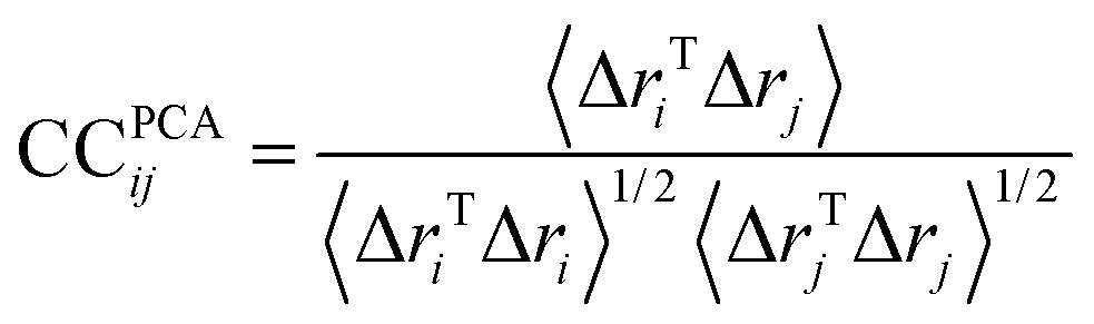
If CC(ij) = 1 the fluctuations of i and j are completely correlated (same phase and period), if CC(ij) = −1 the fluctuations of i and j are completely anticorrelated, and if CC(ij) = 0 the fluctuations of i and j are not correlated. All snapshots were fitted using the transmembrane domain Cα as a reference before performing cross-correlations analysis.
4. Advanced statistical analysis
We performed a statistical analysis of each observed MD trajectory Ξ = {x1, …, xN} using an estimation of the density of the conformations in a low dimensional space using the first modes arising from the PCA. The local occupation density π(x) at a given scale σ is estimated using a Parzen Window density estimator (implemented in MATLAB) with a Gaussian kernel,66,67inducing a free energy landscape
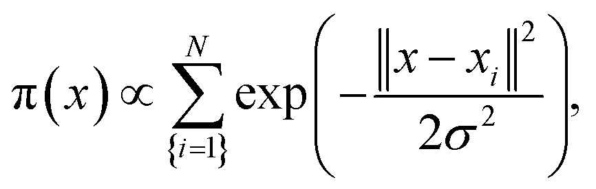
| U(x) = −kBTlog(π(x)) + C. |
This energy should not be identified with the potential (force field) driving the MD simulation, but should be considered as a statistical proxy used to analyse the region of high occupation linked with potential meta-stable states visited by the dynamics. Introducing the similarity matrix68,69 between conformations
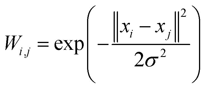 , we have
 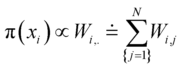 .
.
However, beyond the occupation density some of the dynamical aspects can be empirically analysed through the estimation of a random walk on the simulated data that is compatible with the occupation density. Let us consider a random walk n → Xn on the MD conformations such that the transition probability Pij between i and j is given by
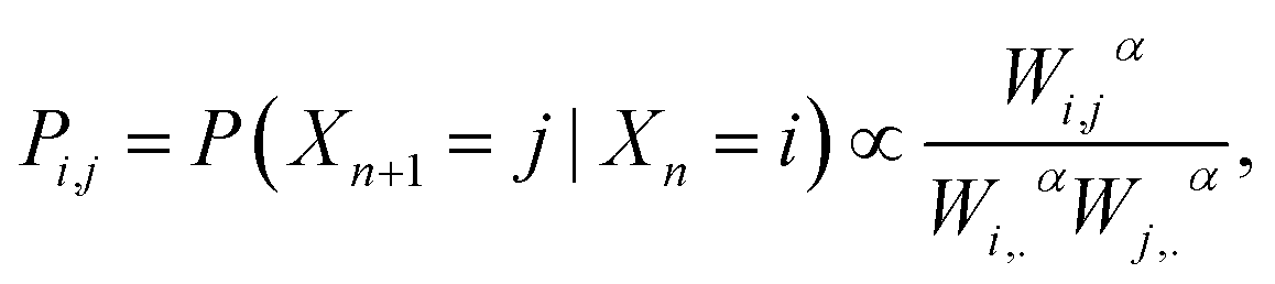 | (4) |
 . After the time change tn = nσ2kBT, this random walk approximates a continuous diffusion t → Xt following a Langevin diffusion
  giving an occupation density π(x) at equilibrium consistent with the observations.38,68,69 The spectral analysis of the associated Laplacian Lij = δij − Pij gives interesting slow variables for the estimated dynamics that are strongly linked with the metastable states.
5. Molecular docking, MD simulations and analysis of the complexes
000 and mutation and crossover rates of 0.02 and 0.8, respectively. The number of runs was set to 100 to explore a large number of poses of the highest affinity, and the Solis and Wets algorithm was used to relax the best 10% of the obtained conformations. The binding pocket coordinates were explicitly defined in the input file.The binding affinity of ligand-hVKORC1 complexes was expressed in terms of number of clusters, poses population and docking scores. For each ligand conformation, the most populated poses (>10%) were saved and analyzed.
The six pdf files supplied contain the atomic coordinates of the ligand–hVKORC1 complexes (ligand = vitKEP and warfarin, W) at t = 0 and t = 100 ns for each trajectory.
| ΔGbind = ΔH − TΔS ≅ ΔEMM + ΔGsol − TΔS | (5) |
| ΔEMM = ΔEint + ΔEelect + ΔEvdw | (6) |
ΔEMM includes ΔEint (covalent bonding including the bond, angle and dihedral energies), electrostatic ΔEelect and van der Waals ΔEvdw energies. The polar contribution was calculated using PB model, while the non-polar free energy estimated by solvent accessible surface area (SASA).
ΔGbind was computed for each generated ligand·target complex over the merged trajectories containing 400 frames (and also for the individual MD simulation replicas over a trajectory containing 200 frames). We used the g_mmpbsa module of GROMACS, which combines subroutines from GROMACS and APBS75 to calculate the enthalpy contribution (ΔH) to the Gibbs free energy and the per-residue energy decomposition. The energy components ΔEMM and the polar and non-polar components of ΔGsol were calculated in the bound and unbound form, and subsequently their contribution to the binding energy ΔRBEx of residue x (ref. 76) was calculated as follows:
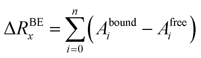 | (7) |
The g_mmpbsa module does not include the calculation of entropic terms and therefore it gives the relative binding energy. Since we have used the analogous compounds showing the same binding mode, the entropy contribution was neglected.44
6. Measuring the dissociation constants of inhibitors
Recombinant hVKORC1 protein was expressed in P. pastoris and microsomal fractions containing recombinant proteins were prepared as described previously.18 VKOR activity was performed as described previously.77 To evaluate the inhibiting effect of acenocoumarol, difenacoum and phenprocoumon on VKOR activity, Ki were determined after addition of anticoagulant to the standard reaction (i.e., 200 mM Hepes buffer (pH 7.4) containing 150 mM KCl, 1 mM dithiothreitol, 0.75 to 2 g L−1 of total proteins containing membrane VKORC1) in the presence of increasing amounts of vitamin K1 epoxide (from 0.003 to 0.2 mM) using anticoagulant concentrations from about 0.05 to 20 × Ki. Data were fitted by non-linear regression to the non-competitive inhibition model4 using the R-fit program. Ki values were obtained from at least three separate experiments performed on three different batches of protein.
 | (8) |
 and
and 
Conflicts of interest
There are no conflicts to declare.Acknowledgements
The authors thanks Eric Solary (Institut Gustave Roussy), Konrad Hinsen (Centre de Biophysique Moléculaire, CNRS Orléans) and Alexey Alexandrov (Ecole Polytechnique) for useful discussions. This work was performed using HPC resources from GENCI-IDRIS (Grant 2015, 2016-077291).References
- D. Y. Jin, J. K. Tie and D. W. Stafford, The conversion of vitamin K epoxide to vitamin K quinone and vitamin K quinone to vitamin K hydroquinone uses the same active site cysteines, Biochemistry, 2007, 46(24), 7279–7283 CrossRef CAS PubMed.
- R. Wallin, N. Wajih and S. M. Hutson, VKORC1: a warfarin-sensitive enzyme in vitamin K metabolism and biosynthesis of vitamin K-dependent blood coagulation factors, Vitam. Horm., 2008, 78, 227–246 CAS.
- J. Stenflo, P. Fernlund, W. Egan and P. Roepstorff, Vitamin K dependent modifications of glutamic acid residues in prothrombin, Proc. Natl. Acad. Sci. U. S. A., 1974, 71(7), 2730–2733 CrossRef CAS.
- B. A. Willems, C. Vermeer, C. P. Reutelingsperger and L. J. Schurgers, The realm of vitamin K dependent proteins: shifting from coagulation toward calcification, Mol. Nutr. Food Res., 2014, 58(8), 1620–1635 CAS.
- G. Karsenty and M. Ferron, The contribution of bone to whole-organism physiology, Nature, 2012, 481(7381), 314–320 CrossRef CAS PubMed.
- K. L. Berkner, Vitamin K-dependent carboxylation, Vitam. Horm., 2008, 78, 131–156 CAS.
- J. Oldenburg, M. Marinova, C. Muller-Reible and M. Watzka, The vitamin K cycle, Vitam. Horm., 2008, 78, 35–62 CAS.
- L. Goodstadt and C. P. Ponting, Vitamin K epoxide reductase: homology, active site and catalytic mechanism, Trends Biochem. Sci., 2004, 29(6), 289–292 CrossRef CAS PubMed.
- N. Wajih, S. M. Hutson and R. Wallin, Disulfide-dependent protein folding is linked to operation of the vitamin K cycle in the endoplasmic reticulum. A protein disulfide isomerase-VKORC1 redox enzyme complex appears to be responsible for vitamin K1 2,3-epoxide reduction, J. Biol. Chem., 2007, 282(4), 2626–2635 CrossRef CAS PubMed.
- W. Li, S. Schulman, R. J. Dutton, D. Boyd, J. Beckwith and T. A. Rapoport, Structure of a bacterial homologue of vitamin K epoxide reductase, Nature, 2010, 463(7280), 507–512 CrossRef CAS PubMed.
- S. Liu, W. Cheng, G. R. Fowle, G. Shen and W. Li, Structures of an intramembrane vitamin K epoxide reductase homolog reveal control mechanisms for electron transfer, Nat. Commun., 2014, 5, 3110 Search PubMed.
- K. J. Czogalla, M. Watzka and J. Oldenburg, Structural Modeling Insights into Human VKORC1 Phenotypes, Nutrients, 2015, 7(8), 6837–6851 CrossRef CAS PubMed.
- S. Rost, A. Fregin, M. Hunerberg, C. G. Bevans, C. R. Muller and J. Oldenburg, Site-directed mutagenesis of coumarin-type anticoagulant-sensitive VKORC1: evidence that highly conserved amino acids define structural requirements for enzymatic activity and inhibition by warfarin, Thromb. Haemostasis, 2005, 94(4), 780–786 Search PubMed.
- N. Wajih, D. C. Sane, S. M. Hutson and R. Wallin, Engineering of a recombinant vitamin K-dependent gamma-carboxylation system with enhanced gamma-carboxyglutamic acid forming capacity: evidence for a functional CXXC redox center in the system, J. Biol. Chem., 2005, 280(11), 10540–10547 CrossRef CAS PubMed.
- J. K. Tie and D. W. Stafford, Structural and functional insights into enzymes of the vitamin K cycle, J. Thromb. Haemostasis, 2016, 14(2), 236–247 CrossRef CAS PubMed.
- B. W. Weston and P. E. Monahan, Familial deficiency of vitamin K-dependent clotting factors, Haemophilia, 2008, 14(6), 1209–1213 CrossRef CAS PubMed.
- M. Teichert, L. E. Visser, R. H. van Schaik, A. Hofman, A. G. Uitterlinden and P. A. De Smet, et al., Vitamin K epoxide reductase complex subunit 1 (VKORC1) polymorphism and aortic calcification: the Rotterdam Study, Arterioscler., Thromb., Vasc. Biol., 2008, 28(4), 771–776 CrossRef CAS PubMed.
- A. Hodroge, B. Matagrin, C. Moreau, I. Fourel, A. Hammed and E. Benoit, et al., VKORC1 mutations detected in patients resistant to vitamin K antagonists are not all associated with a resistant VKOR activity, J. Thromb. Haemostasis, 2012, 10(12), 2535–2543 CrossRef CAS PubMed.
- S. Rost, A. Fregin, V. Ivaskevicius, E. Conzelmann, K. Hortnagel and H. J. Pelz, et al., Mutations in VKORC1 cause warfarin resistance and multiple coagulation factor deficiency type 2, Nature, 2004, 427(6974), 537–541 CrossRef CAS PubMed.
- T. Li, C. Y. Chang, D. Y. Jin, P. J. Lin, A. Khvorova and D. W. Stafford, Identification of the gene for vitamin K epoxide reductase, Nature, 2004, 427(6974), 541–544 CrossRef CAS PubMed.
- W. D. Van Horn, Structural and functional insights into human vitamin K epoxide reductase and vitamin K epoxide reductase-like1, Crit. Rev. Biochem. Mol. Biol., 2013, 48(4), 357–372 CrossRef CAS PubMed.
- K. J. Czogalla, A. Biswas, A. C. Wendeln, P. Westhofen, C. R. Muller and M. Watzka, et al., Human VKORC1 mutations cause variable degrees of 4-hydroxycoumarin resistance and affect putative warfarin binding interfaces, Blood, 2013, 122(15), 2743–2750 CrossRef CAS PubMed.
- J. K. Tie, C. Nicchitta, H. G. von and D. W. Stafford, Membrane topology mapping of vitamin K epoxide reductase by in vitro translation/cotranslocation, J. Biol. Chem., 2005, 280(16), 16410–16416 CrossRef CAS PubMed.
- J. K. Tie, D. Y. Jin and D. W. Stafford, Human vitamin K epoxide reductase and its bacterial homologue have different membrane topologies and reaction mechanisms, J. Biol. Chem., 2012, 287(41), 33945–33955 CrossRef CAS PubMed.
- H. G. von, Control of topology and mode of assembly of a polytopic membrane protein by positively charged residues, Nature, 1989, 341(6241), 456–458 CrossRef PubMed.
- E. Hartmann, T. A. Rapoport and H. F. Lodish, Predicting the orientation of eukaryotic membrane-spanning proteins, Proc. Natl. Acad. Sci. U. S. A., 1989 Aug, 86(15), 5786–5790 Search PubMed.
- Z. Cao, L. M. van, L. J. Mitchell, M. A. Pringle, K. Inaba and N. J. Bulleid, The membrane topology of vitamin K epoxide reductase is conserved between human isoforms and the bacterial enzyme, Biochem. J., 2016, 473(7), 851–858 CrossRef CAS PubMed.
- L. A. Rutkevich and D. B. Williams, Vitamin K epoxide reductase contributes to protein disulfide formation and redox homeostasis within the endoplasmic reticulum, Mol. Biol. Cell, 2012, 23(11), 2017–2027 CrossRef CAS PubMed.
- S. Schulman, B. Wang, W. Li and T. A. Rapoport, Vitamin K epoxide reductase prefers ER membrane-anchored thioredoxin-like redox partners, Proc. Natl. Acad. Sci. U. S. A., 2010, 107(34), 15027–15032 CrossRef CAS PubMed.
- P. Dowd, S. W. Ham, S. Naganathan and R. Hershline, The mechanism of action of vitamin K, Annu. Rev. Nutr., 1995, 15, 419–440 CrossRef CAS PubMed.
- M. A. Rishavy, A. Usubalieva, K. W. Hallgren and K. L. Berkner, Novel insight into the mechanism of the vitamin K oxidoreductase (VKOR): electron relay through Cys43 and Cys51 reduces VKOR to allow vitamin K reduction and facilitation of vitamin K-dependent protein carboxylation, J. Biol. Chem., 2011, 286(9), 7267–7278 CrossRef CAS PubMed.
- B. A. Soute, M. M. Groenen-van Dooren, A. Holmgren, J. Lundstrom and C. Vermeer, Stimulation of the dithiol-dependent reductases in the vitamin K cycle by the thioredoxin system. Strong synergistic effects with protein disulphide-isomerase, Biochem. J., 1992, 281(1), 255–259 CrossRef CAS PubMed.
- H. M. Berman, J. Westbrook, Z. Feng, G. Gilliland, T. N. Bhat and H. Weissig, et al., The Protein Data Bank, Nucleic Acids Res., 2000, 28(1), 235–242 CrossRef CAS PubMed.
- S. Wu, J. K. Tie, D. W. Stafford and L. G. Pedersen, Membrane topology for human vitamin K epoxide reductase, J. Thromb. Haemostasis, 2014, 12(1), 112–114 CrossRef CAS PubMed.
- D. E. Warschawski, A. A. Arnold, M. Beaugrand, A. Gravel, E. Chartrand and I. Marcotte, Choosing membrane mimetics for NMR structural studies of transmembrane proteins, Biochim. Biophys. Acta, 2011, 1808(8), 1957–1974 CrossRef CAS PubMed.
- W. Kabsch and C. Sander, Dictionary of protein secondary structure: pattern recognition of hydrogen-bonded and geometrical features, Biopolymers, 1983, 22(12), 2577–2637 CrossRef CAS PubMed.
- U. Von Luxbourg, A tutorial on spectral Clustering. Statistics and Computing, 2007, vol. 17(4), arXiv:0711.0189.
- B. Nadler, S. Lafon, R. R. Coifman and I. G. Kevrekidis, Diffusion maps, spectral clustering and eigenfunctions of Fokker-Planck operators, Neural Information Processing Systems, 2005, p. 18 Search PubMed.
- B. Chalmond, Modeling and Inverse Problem in Image Analysis, Applied Mathematical Sciences, 2003, p. 155 Search PubMed.
- R. Harada and A. Kitao, Parallel Cascade Selection Molecular Dynamics (PaCS-MD) to generate conformational transition pathway, J. Chem. Phys., 2013, 139(3), 035103 CrossRef PubMed.
- G. V. Le, P. Schmidtke and P. Tuffery, Fpocket: an open source platform for ligand pocket detection, BMC Bioinf., 2009, 10, 168 CrossRef PubMed.
- G. M. Morris, R. Huey, W. Lindstrom, M. F. Sanner, R. K. Belew and D. S. Goodsell, et al., AutoDock4 and AutoDockTools4: Automated docking with selective receptor flexibility, J. Comput. Chem., 2009, 30(16), 2785–2791 CrossRef CAS PubMed.
- B. Matagrin, A. Hodroge, A. Montagut-Romans, J. Andru, I. Fourel and S. Besse, et al., New insights into the catalytic mechanism of vitamin K epoxide reductase (VKORC1) – The catalytic properties of the major mutations of rVKORC1 explain the biological cost associated to mutations, FEBS Open Bio, 2013, 3, 144–150 CrossRef CAS PubMed.
- T. Hou, J. Wang, Y. Li and W. Wang, Assessing the performance of the MM/PBSA and MM/GBSA methods. 1. The accuracy of binding free energy calculations based on molecular dynamics simulations, J. Chem. Inf. Model., 2011, 51(1), 69–82 CrossRef CAS PubMed.
- K. J. Czogalla, A. Biswas, K. Honing, V. Hornung, K. Liphardt and M. Watzka, et al., Warfarin and vitamin K compete for binding to Phe55 in human VKOR, Nat. Struct. Mol. Biol., 2017, 24(1), 77–85 CAS.
- W. Jiang and B. Roux, Free Energy Perturbation Hamiltonian Replica-Exchange Molecular Dynamics (FEP/H-REMD) for Absolute Ligand Binding Free Energy Calculations, J. Chem. Theory Comput., 2010, 6(9), 2559–2565 CrossRef CAS PubMed.
- B. Webb and A. Sali, Comparative Protein Structure Modeling Using MODELLER, Curr Protoc Bioinformatics, 2016, 86, 2 Search PubMed.
- M. M. Ghahremanpour, S. S. Arab, S. B. Aghazadeh, J. Zhang and D. Van Der Spoel, MemBuilder: a web-based graphical interface to build heterogeneously mixed membrane bilayers for the GROMACS biomolecular simulation program, Bioinformatics, 2014, 30(3), 439–441 CrossRef CAS PubMed.
- J. P. Jambeck and A. P. Lyubartsev, Derivation and systematic validation of a refined all-atom force field for phosphatidylcholine lipids, J. Phys. Chem. B, 2012, 116(10), 3164–3179 CrossRef PubMed.
- D. J. Price and C. L. Brooks III, A modified TIP3P water potential for simulation with Ewald summation, J. Chem. Phys., 2004, 121(20), 10096–10103 CrossRef CAS PubMed.
- M. G. Wolf, M. Hoefling, C. Aponte-Santamaria, H. Grubmuller and G. Groenhof, g_membed: Efficient insertion of a membrane protein into an equilibrated lipid bilayer with minimal perturbation, J. Comput. Chem., 2010, 31(11), 2169–2174 CrossRef CAS PubMed.
- S. O. Yesylevskyy, ProtSqueeze: simple and effective automated tool for setting up membrane protein simulations, J. Chem. Inf. Model., 2007, 47(5), 1986–1994 CrossRef CAS PubMed.
- D. Van Der Spoel, E. Lindahl, B. Hess, G. Groenhof, A. E. Mark and H. J. Berendsen, GROMACS: fast, flexible, and free, J. Comput. Chem., 2005, 26(16), 1701–1718 CrossRef CAS PubMed.
- R. B. Best, X. Zhu, J. Shim, P. E. Lopes, J. Mittal and M. Feig, et al., Optimization of the additive CHARMM all-atom protein force field targeting improved sampling of the backbone phi, psi and side-chain chi(1) and chi(2) dihedral angles, J. Chem. Theory Comput., 2012, 8(9), 3257–3273 CrossRef CAS PubMed.
- G. Bussi, D. Donadio and M. Parrinello, Canonical sampling through velocity rescaling, J. Chem. Phys., 2007, 126(1), 014101 CrossRef PubMed.
- W. F. van Gunsteren and H. J. Berendsen, Computer simulation as a tool for tracing the conformational differences between proteins in solution and in the crystalline state, J. Mol. Biol., 1984, 176(4), 559–564 CrossRef CAS PubMed.
- W. G. Hoover, Canonical dynamics: equilibrium phase-space distributions, Phys. Rev. A Gen. Phys., 1985, 31(3), 1695–1697 CrossRef.
- V. J. de, R. M. Scheek, W. F. van Gunsteren, H. J. Berendsen, R. Kaptein and J. Thomason, Combined procedure of distance geometry and restrained molecular dynamics techniques for protein structure determination from nuclear magnetic resonance data: application to the DNA binding domain of lac repressor from Escherichia coli, Proteins: Struct., Funct., Genet., 1988, 3(4), 209–218 CrossRef PubMed.
- L. Verlet, Computer “Experiments” on Classical Fluids. I. Thermodynamical Properties of Lennard-Jones Molecules, Phys. Rev., 1967, 159(1), 98–103 CrossRef CAS.
- D. M. York, A. Wlodawer, L. G. Pedersen and T. A. Darden, Atomic-level accuracy in simulations of large protein crystals, Proc. Natl. Acad. Sci. U. S. A., 1994, 91(18), 8715–8718 CrossRef CAS.
- S. Yuan, H. C. Chan, S. Filipek and H. Vogel, PyMOL and Inkscape Bridge the Data and the Data Visualization, Structure, 2016, 24(12), 2041–2042 CrossRef CAS PubMed.
- W. Humphrey, A. Dalke and K. Schulten, VMD: visual molecular dynamics, J. Mol. Graphics, 1996, 14(1), 33–38 CrossRef CAS PubMed.
- B. J. Grant, A. P. Rodrigues, K. M. ElSawy, J. A. McCammon and L. S. Caves, Bio3d: an R package for the comparative analysis of protein structures, Bioinformatics, 2006, 22(21), 2695–2696 CrossRef CAS PubMed.
- E. Lyman and D. M. Zuckerman, Ensemble-based convergence analysis of biomolecular trajectories, Biophys. J., 2006, 91(1), 164–172 CrossRef CAS PubMed.
- X. Daura, W. F. van Gunsteren and A. E. Mark, Folding-unfolding thermodynamics of a beta-heptapeptide from equilibrium simulations, Proteins: Struct., Funct., Genet., 1999, 34(3), 269–280 CrossRef CAS.
- E. Parzen, On Estimation of a Probability Density Function and Mode, Ann. Math. Stat., 1962, 33(3), 1065–1076 CrossRef.
- B. W. Silverman, Density Estimation for Statistics and Data Analysis. Monographs on Statistics and Applied Probability, Chapman and Hall, London, 1986, vol. 48 Search PubMed.
- R. R. Coifman, I. G. Kevrekidis, S. Lafon, M. Maggioni and B. Nadler, Diffusion Maps, Reduction Coordinates, and Low Dimensional Representation of Stochastic Systems, Multiscale Model. Simul., 2008, 7, 842–864 Search PubMed.
- B. Nadler, S. Lafon, R. R. Coifman and I. G. Kevrekidis, Diffusion maps, spectral clustering and reaction coordinates of dynamical systems, Appl. Comput. Harmon. Anal., 2006, 21, 113–127 CrossRef.
- A. B. Wohri, W. Y. Wahlgren, E. Malmerberg, L. C. Johansson, R. Neutze and G. Katona, Lipidic sponge phase crystal structure of a photosynthetic reaction center reveals lipids on the protein surface, Biochemistry, 2009, 48(41), 9831–9838 CrossRef PubMed.
- E. F. Pettersen, T. D. Goddard, C. C. Huang, G. S. Couch, D. M. Greenblatt and E. C. Meng, et al., UCSF Chimera–a visualization system for exploratory research and analysis, J. Comput. Chem., 2004, 25(13), 1605–1612 CrossRef CAS PubMed.
- D. Elenkova, B. Morgenstern, I. Manolov and M. Milanova, Synthesis, crystal structure and physico-chemical properties of 3,3'-[(4-hydroxyphenyl)methyl] bis-(4-hydroxy-2H-chromen-2-one), Acta Chim. Slov., 2014, 61(4), 718–728 CAS.
- V. Zoete, M. A. Cuendet, A. Grosdidier and O. Michielin, SwissParam: a fast force field generation tool for small organic molecules, J. Comput. Chem., 2011, 32(11), 2359–2368 CrossRef CAS PubMed.
- F. J. Solis and R. J.-B. Wets, Minimization by Random Search Techniques, Math. Oper. Res., 1981, 6, 19–30 CrossRef.
- N. A. Baker, D. Sept, S. Joseph, M. J. Holst and J. A. McCammon, Electrostatics of nanosystems: application to microtubules and the ribosome, Proc. Natl. Acad. Sci. U. S. A., 2001, 98(18), 10037–10041 CrossRef CAS PubMed.
- R. Kumari, R. Kumar and A. Lynn, g_mmpbsa–a GROMACS tool for high-throughput MM-PBSA calculations, J. Chem. Inf. Model., 2014, 54(7), 1951–1962 CrossRef CAS PubMed.
- A. Hodroge, C. Longin-Sauvageon, I. Fourel, E. Benoit and V. Lattard, Biochemical characterization of spontaneous mutants of rat VKORC1 involved in the resistance to antivitamin K anticoagulants, Arch. Biochem. Biophys., 2011, 515(1–2), 14–20 CrossRef CAS PubMed.
Footnotes |
| † Functional States of VKOR/N. Chatron et al. |
| ‡ Electronic supplementary information (ESI) available: 11 figures, 1 table and methods details. See DOI: 10.1039/c7ra07463h |
| This journal is © The Royal Society of Chemistry 2017 |