
 Open Access Article
 This Open Access Article is licensed under a
 Creative Commons Attribution 3.0 Unported Licence
Design and synthesis of a free-standing carbon nano-fibrous web electrode with ultra large pores for high-performance vanadium flow batteries
Chi Xuac,
Xianfeng Li ab,
Tao Liu*a and
Huamin Zhang*ab
ab,
Tao Liu*a and
Huamin Zhang*ab
aDivision of Energy Storage, Dalian Institute of Chemical Physics, Chinese Academy of Sciences, Dalian 116023, China. E-mail: liutao@dicp.ac.cn; zhanghm@dicp.ac.cn
bCollaborative Innovation Center of Chemistry for Energy Materials (iChEM), Dalian 116023, China
cUniversity of Chinese Academy of Sciences, Beijing 100039, China
First published on 26th September 2017
Abstract
To improve the transport of active species in the carbon nano-fibrous electrodes of a vanadium flow battery (VFB), a free-standing carbon nano-fibrous web with ultra large pores has been designed and fabricated through the horizontally-opposed blending electrospinning method in this study. The morphology, surface chemistry and electrochemical performances of the highly porous nano-fibrous web have been investigated and compared with the carbon nano-fibrous web prepared by traditional electrospinning. Benefiting from the much larger pore size and higher porosity of the carbon nano-fibrous web prepared by horizontally-opposed blending electrospinning, the concentration polarization of the vanadium flow battery is effectively reduced. As indicated by the single cell tests, the battery using horizontally-opposed blending electrospun carbon nano-fibrous web electrodes delivers much improved performance, especially at high current density. The voltage efficiency is 10.3% higher than that of the traditional electrospun carbon nano-fibrous web electrodes and the electrolyte utilization efficiency is twice as much as that of the traditional electrospun carbon nano-fibrous web electrodes at 60 mA cm−2. The results suggest that expanding the pore size could be one effective strategy to facilitate carbon nano-fibrous materials' applications for VRBs, and that the horizontally-opposed blending electrospun carbon nano-fibrous web is a promising electrode candidate for VFBs.
Introduction
With the gradual depletion of non-renewable energies and increasing concern about environmental issues, the development and application of renewable energies such as solar energy and wind energy are attracting worldwide attention.1 However, due to the intrinsic properties of unpredictability and intermittence, renewable solar and wind energies cannot produce a high quality, stable power output. Therefore, effective energy storage technologies are urgently needed for load leveling and peak shaving.2,3 Among these technologies of energy storage, the vanadium flow battery (VFB) possesses plenty of advantages, including long life cycle, high stability, instant response, efficient energy conversion, adjustable design, cost-effective operation and maintenance etc., and has received overwhelming attention as a promising energy storage technology for large scale energy storage applications.4–6 In VFB, VO2+/VO2+ and V2+/V3+ redox couples are utilized as the positive and negative half-cells, respectively, which can deliver an open circuit voltage approximately at 1.26 V.7,8 By deploying the same element, the contamination of metal cations is eliminated. Nevertheless, there are still some hindrances for VFB to the commercial applications, especially the low energy efficiency (EE) and low electrolyte utilization efficiency.9 Since the EE of VFB is closely relied on the physiochemical properties of the electrodes where the electrochemical reactions of vanadium ions take place, it is crucial to design and synthesis suitable electrodes for high performance VFB.Though a lot of materials have been introduced to act as electrodes for VFB, carbon materials have dominated the attention with their typical merits.10–13 Carbon felt and graphite felt, especially, have been widely used as electrodes in VFB owing to their excellent chemical stability and conductivity.14 However, low electrochemical activity and limited reactive surface area which result in the large polarization and low EE during operation greatly restrain the performance of the power storage. Therefore, it's of great importance to increase the electrochemical activity and enlarge the reactive surface area of VFB electrodes.15–19 Lots of efforts have been devoted to improving the electrochemical performance of carbon material electrodes.1,20,21 One common method is to modify the surface of carbon materials with the N- or O-functional groups. For example, due to hydrophobic property, the graphite felts have to be subjected to surface treatments before being utilized as electrodes to ensure their electrochemical activity and wettability. Flox et al.22 introduced thermos-chemical treatments based on NH3/O2 to modify the surface of graphite felts. Lee et al.23 used the hydrothermal method to develop a nitrogen-doped carbon felt electrode. Kim et al.24 investigated the effect of surface treatment combining corona discharge and hydrogen peroxide on the electrochemical performance of carbon felt as electrodes for VFB, they explained the O-group on the surface of carbon felt can improve the electrochemical activity. Another method is to introduce electrocatalysts which could significantly increase the electrochemical performance of carbon felt electrodes for VFB.25,26 Li et al.16 introduced bismuth nanoparticles to decorate graphite felt as an electrocatalyst to enhance the kinetics of the sluggish V2+/V3+ redox reaction. While Yao et al.27 found W2O3 had the catalytic activity for both positive electrode and negative electrode. Kim et al.28 employed a non-precious metal oxides Mn3O4 as a novel catalyst to enhance the electrochemical performance of carbon felt electrodes for VFB.
In addition to carbon felt and graphite felt electrodes, carbon nano materials also attract tremendous attentions for their large specific surface area and high electrochemical activity properties. He et al.15 introduced carbon nanotube with Mn3O4 on it to VFB system as electrodes which appeared remarkable electrochemical performance. At the same time, Li et al.11 used multiwall carbon nanotube as the electrochemical catalyst for electrode reactions. However, those carbon nanomaterials are complicated and costly to synthesis, and the powder materials are not convenient to use in VFB, directly. Recently, electrospinning carbon nano-fibers in the form of electro-conducting non-woven webs (ECNFWs) have been introduced into the VFB. The promising technique is an efficient approach to prepare free-standing carbon nanofibers with high activity and electro-conductivity on a large scale. Yan et al.29 investigated the effect of carbonization temperature, carbonization time on the carbon structure of ECNFW and found the high electrochemical activity of ECNFW towards VO2+/VO2+ reaction. Then they used it directly as the catalyst layer for VFB.30 Fetyan et al.31 found that an increase in the energy efficiency of about 10% was achieved when using five sheets of the free-standing ECNFWs compared to the commercial carbon felts. Besides, researchers further studied the optimal fiber size by modeling work and prepared various sizes of electrospinning nano fibers by barely adjusting the concentration of polyacrylonitrile (PAN) precursor.32 In order to further enhance the electrochemical reversibility between the electrode–electrolyte interfaces, various oxides are also introduced to decorate the ECNFWs, including Mn3O4, V2O3, CoO etc.33–35 However, although the high activity, high conductivity and free-standing properties of carbon nano-fibrous electrodes have been achieved by the electrospinning technique, the intrinsic low porosity, small pore diameter, and poor wettability of electrospinning carbon nanofibers turn out to be disadvantageous in VFB system.36,37 When using liquids as reactants, the sluggish transport of the active species in dense carbon nano-fibrous electrodes will induce a large concentration polarization, which is the main reason for the poor performances, especially the low EE and low electrolyte utilization efficiency.38 Many efforts have been tried to prepare porous electrospinning nano fibers.39–41 The phase separation was coupled with electrospinning to produce polyacrylonitrile (PAN) and polystyrene (PS) bicomponent electrospun fibers, then, upon removal of the phase-separated PS domains by solvent extraction, the fibers became nanoporous.42 However, the investigation of porous ECNFWs for VFB is still lack of study.
Herein, we rationally designed and synthesised a free-standing carbon nano-fibrous web electrode with high porosity and large pore size through a novel horizontally-opposed blending electrospinning method (BECNFW) and compared it with traditional ECNFW. Two precursors (PAN solution and PVP solution) were employed for the electrospinning. When removing PVP fibers, the ultra large pores were produced between residual PAN fibers. As indicated by the single battery test and EIS results, the concentration polarization of battery with BECNFW electrodes is effectively reduced, which making the battery deliver much improved performances.
Experimental
Materials synthesis
The facile synthesis procedures of BECNFW is outlined in Fig. 1, while the details are mentioned below. Two kinds of precursor solutions for electrospinning were prepared firstly. One was PAN precursor solution made by dissolving 10 wt% PAN in N,N-dimethylformamide (DMF) and stirring at 70 °C for 8 h. And the other was PVP precursor solution prepared by dissolving 20 wt% PVP in deionized water and stirring at 40 °C for 8 h. For the horizontally-opposed blending electrospinning, one side was the PAN precursor solution, and the horizontally-opposed side was the PVP precursor solution. Then, a positive direct current voltage of 15 kV was applied to both sides by a voltage regulated DC power supply to generate the polymer jet. The PAN precursor-feeding rate was 1 mL h−1 with a metal needle with the diameter 0.8 mm as a spinneret. The PVP precursor-feeding rate was 0.5 mL h−1 with a metal needle with the diameter of 0.6 mm as a spinneret. PAN and PVP nanofibers were collected on a rotating drum collector that was placed between PAN and PVP sides at a rotating speed of 200 rpm. The distance between the PAN side metal needle and the metal collector was fixed at 15 cm. To the other side, the distance was 10 cm. After that, the mixed PAN and PVP nanofibers were immerged in 10 wt% ethanol/water solution for 12 h and then immerged in deionized water for 12 h to remove the PVP nanofibers. The remained PAN nanofibers were preoxidized at 250 °C for 1 h in air and then carbonized by heating to 1100 °C for 1 h at a heating rate of 5 °C min−1 in Ar atmosphere. For comparison, ECNFW was also prepared by the reported traditional electrospinning method without further 10 wt% ethanol/water treatment.31,38 Only 10 wt% PAN in DMF was used as the precursor solution.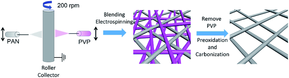 | ||
| Fig. 1 Synthesis procedures of BECNFW. | ||
Physical properties
The surface morphologies of ECNFW and BECNFW were characterized with a scanning electron microscopy (SEM, JEOL/EO, JCM-6000 Instrument, Japan) at an accelerating voltage of 15 kV. The surface elements and the functional groups of ECNFW and BECNFW were detected by X-ray photoelectron spectroscopy (XPS, ESCALAB250 system) utilizing Al Kα monochromatic (1486.6 eV) with a spot area of 500 μm. The spectra was calibrated according to the C 1s (284.7 eV) peak.Electrochemical properties
The electrochemical performances of as-prepared ECNFW and BECNFW electrodes were evaluated by the cyclic voltammetry (CV). For the electrochemical tests, a three-electrode system was utilized with ECNFW or BECNFW as the working electrode, a saturated calomel electrode (SCE) as the reference electrode and the graphite plate as the counter electrode. The working electrodes were prepared by sandwiching a piece of ECNFW or BECNFW between two plastic sheets, and the working area was fixed at 0.385 cm2 by an open circular hole. A piece of Cu foil contacted to the ECNFW served as the current collector. The investigations for VO2+/VO2+ and V2+/V3+ redox couples were carried out in 0.05 M VO2+ + 0.05 M VO2+ + 3 M H2SO4 and 0.05 M V2+ + 0.05 M V3+ + 3 M H2SO4, respectively. CV results were recorded on the CHI604E workstation (CH Instruments, USA).VFB single cell performance
The performances of the VFB single cells using BECNFW or ECNFW as symmetric electrodes were investigated. The positive and negative electrodes were the same BECNFW or ECNFW with an active area of 9 cm2 (3.0 × 3.0 cm). A Nafion 115 membrane (DuPont, USA) was used as the ion exchange membrane. The graphite plates with serpentine channels on its surface served as the current collector. The cell was sealed with rubber washers. Charge–discharge test was conducted on a battery test system Arbin-BT 2000 instrument (Arbin Co., USA) with a constant current density from 20 to 80 mA cm−2. The charge/discharge cutoff voltage was set as 1.65 V and 1.0 V, respectively. 30 mL 1.5 M V3+ in 3.0 M H2SO4 solution and 30 mL 1.5 M VO2+ in 3.0 M H2SO4 solution were used as negative and positive electrolytes, respectively.The EIS of VFB single cell was measured using a KFM2030 (Kikusui electronics Co., Japan) impedance meter in a frequency range from 0.01 Hz to 10 kHz with an AC amplitude of 165 mA. Before starting the EIS measurements, the cell was charged at the state of charge (SOC) of 50% using the battery test system.
Result and discussion
Morphologies of BECNFW and ECNFW were investigated with scanning electron microscopy (SEM), and are demonstrated in Fig. 2. Both ECNFW and BECNFW samples exhibit the similar fibers cross-linked structures. Carbon nanofibers are distributed randomly to form a 3-dimension web structure and the surfaces of carbon nanofibers are generally smooth. The diameters of ECNFW fibers are ranging from 200–400 nm, which is similar previous reported result.38 While for BECNFW, the diameters of fibers are ranging from 200–800 nm. However, it can be clearly seen that BECNFW is much looser than ECNFW, which is attributed to the sacrificing template effect of PVP nanofibers. During the process of horizontally-opposed blending electrospinning, both PAN and PVP nano fibers are gathered by rotating drum collector. When the PVP nano fibers were removed, the space among PAN nano fibers of BECNFW will be enlarged than that of ECNFW. As shown in Fig. 2a and b, the distance between adjacent fibers of BECNFW is as large as 16 μm, while that of ECNFW is less 4 μm. The further magnified pictures in Fig. 2b and d can support this conclusion. The highly porous structure of the BECNFW will be beneficial to the diffusion of active species in the electrode of VRB and promote the performances of VRB.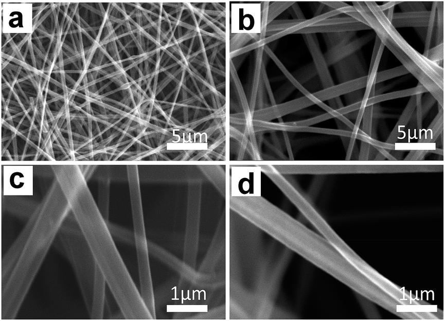 | ||
| Fig. 2 SEM images of ECNFW and BECNFW: (a and c) ECNFW; (b and d) BECNFW. | ||
The surface elements and the functional groups of ECNFW and BECNFW were detected by XPS. As shown in Fig. 3, O-groups or N-groups on the surface of BECNFW are all much less than that of ECNFW. As listed in Table 1, the concentrations of O-groups and N-groups on the surface of BECNFW are 0.89% and 1.49% while those for ECNFW are 4.17% and 3.59%, respectively. It is possible that the using of 10 wt% ethanol water solution to remove the PVP nano fibers from the mixture of PAN and PVP nano fibers also dissolves a large amount of the organic functional groups on the surface of PAN nano fibers, which leads to the reduction of O-groups or N-groups on the surface of BECNFW.
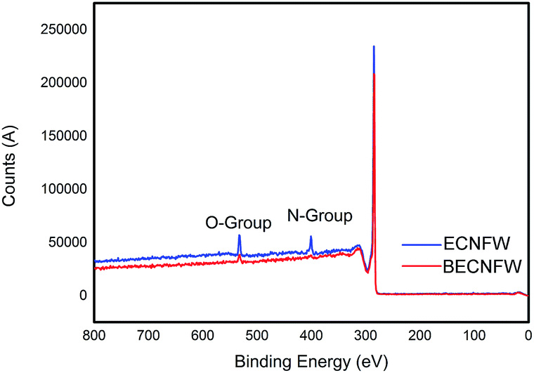 | ||
| Fig. 3 Nitrogen species and oxygen species concentrations on the surface of ECNFW and BECNFW. | ||
| Ea (V) | Ec (V) | ΔEp (V) | O-group | N-group | ||
|---|---|---|---|---|---|---|
| ECNFW | VO2+/VO2+ | 0.947 | 0.766 | 0.181 | 4.17% | 3.59% |
| V2+/V3+ | −0.456 | −0.572 | 0.116 | |||
| BECNFW | VO2+/VO2+ | 0.962 | 0.753 | 0.209 | 0.89% | 1.49% |
| V2+/V3+ | −0.196 | −0.844 | 0.648 |
The electrochemical performance were assessed by cyclic voltammetry (CV) test at a can rate of 10 mV s−1. The CV behaviors of cathode and anode half cells are shown in Fig. 4a and b, respectively. Both BECNFW and ECNFW exhibit the apparent anodic and cathodic peaks associated with the redox potential of VO2+/VO2+. As concluded in Table 1, the anodic/cathodic peak potential of ECNFW appears at around 0.947 V/0.766 V, and that of BECNFW is 0.962 V/0.753 V. Compared with ECNFW, the potential differences (ΔEp) between anodic peak and cathodic peak are similar, and the ratio of the anodic peak current and cathodic peak current density (Ipa/Ipc) are both close to 1, indicating that both ECNFW and BECNFW can exhibit the excellent electrocatalytic activity and kinetic reversibility towards VO2+/VO2+ redox couples. However, though both BECNFW and ECNFW can exhibit apparent anodic and cathodic peaks associated with V2+/V3+, the anodic and cathodic peak currents of BECNFW are almost reduced to half of that of ECNFW and the ΔEp increases from around 116 mV to 648 mV. The reduction of O-groups or N-groups on the surface of BECNFW is ascribed to lower electroactivity of the anode side, since the O-groups or N-groups are reported to be electrocatalysis for the redox reaction of V2+/V3+. According to previous reports, the electrochemical activity of electrospinning nanofibers are much higher than non nano-materials (carbon felt or graphite felt) due to their large specific surface area which introduces more active sites.31,32 So that it can be used as the catalyst layer directly for VFB.30,43 Though the electrochemical activity of BECNFW is impaired, especially the negative side, since the amounts O-groups or N-groups are reduced, the electrochemical activity is still higher than reported carbon felt.31 The highly porous structure with larger pore sizes still possesses great advantages for VRB.
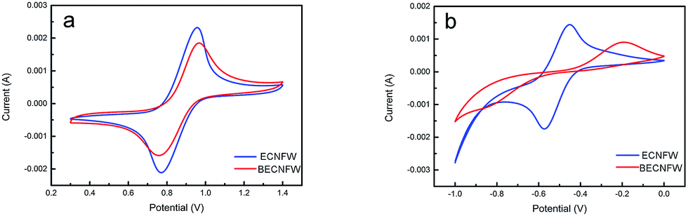 | ||
| Fig. 4 CV curves of half cell: (a) VO2+/VO2+ redox couple on the ECNFW and BECNFW; (b) V3+/V2+ redox couples on the ECNFW and BECNFW. | ||
The performance of the VFB single cell using BECNFW or ECNFW as symmetric electrodes was investigated, respectively. As shown in Fig. 5a, the VFB with BECNFW electrodes can be well charged and discharged from 20 to 80 mA cm−2, and its coulombic efficiency (CE), voltage efficiency (VE) and EE reached 95.4%, 81.6% and 77.9% at a current density of 60 mA cm−2, respectively. While as shown in Fig. 5b, the VFB with ECNFW electrodes only can be well charged and discharged from 20–60 mA cm−2, and its CE, VE and EE only reached 93.6%, 71.3% and 66.8% at a current density of 60 mA cm−2, respectively. Table 2 summarizes the performances of the two VFBs at different current densities. It is worth noting that the energy efficiencies of VFB single cell with BECNFW electrodes are all higher than that of the VFB with ECNFW electrodes. With the current density increasing, the differences become more distinguishable when operating at higher current density. The VFB with ECNFW electrodes could not even work under the current density of 80 mA cm−2. It indicates that though the electroactivities of vanadium redox pairs are a bit poorer on BECNFW electrodes than that on ECNFW, the performances of VFB with BECNFW electrodes are much improved, especially under high current density, attributing to higher porous structure and larger pore size of BECNFW.
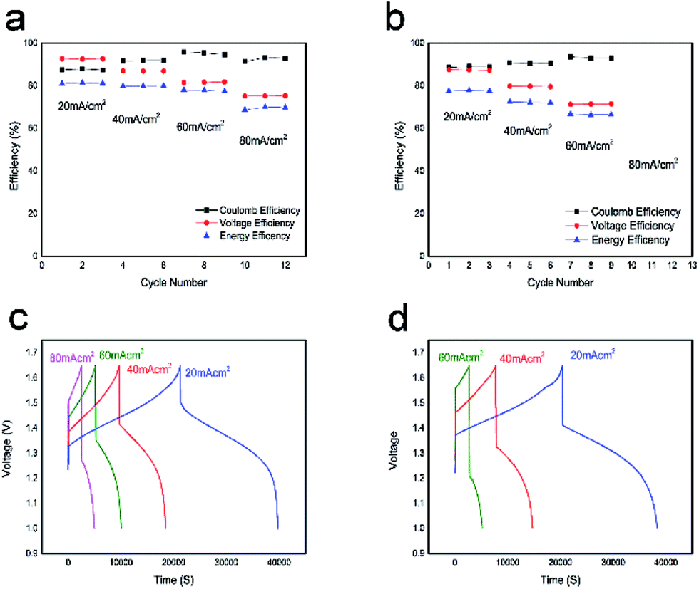 | ||
| Fig. 5 Single cell performance of ECNFW and BECNFW: (a) CE, VE and EE of single cell with BECNFW; (b) CE, VE and EE of single cell with ECNFW; (c) charge–discharge curve of VFB with BECNFW; (d) charge–discharge curve of VFB with ECNFW. | ||
| 20 mA cm−2 | 40 mA cm−2 | 60 mA cm−2 | 80 mA cm−2 | ||
|---|---|---|---|---|---|
| BECNFW | CE | 87.9% | 91.9% | 95.4% | 93.2% |
| VE | 92.6% | 86.9% | 81.6% | 75.2% | |
| EE | 81.4% | 79.9% | 77.9% | 70% | |
| ECNFW | CE | 88.6% | 90.5% | 93.6% | — |
| VE | 87.6% | 79.7% | 71.3% | — | |
| EE | 77.6% | 72.2% | 66.8% | — |
Fig. 5c and d show a series of charge and discharge profiles of VFBs with BECNFW and ECNFW as the electrodes, respectively. As observed, the charging and discharging take-off potentials of VFBs with BECNFW electrodes are 110 mV lower and 150 mV higher than that of VFB with ECNFW electrode at a current density of 60 mA cm−2, respectively. Besides, the charging and discharging capacities of VFB with BECNFW electrodes are almost twice as those of VFB with ECNFW electrodes. It means that with the same quantity of electrolyte, the electrolyte utilization efficiency of VFB with BECNFW electrodes is also twice as that VFB with of ECNFW. The reason is that BECNFW electrodes with its intrinsic advantages of high porosity and the large pore size over the ECNFW electrodes, facilitates penetration of the electrolyte to electrodes and reacts more active species. EIS of the single cells were also conducted to explain these results. As reported, on the polarizations of VFB single cells, the Nyquist plots for VFBs obtained at the state of charge (SOC) of 50% can be fitted by an equivalent circuit (EC) model, as shown in the inset of Fig. 6.44 The elements in the equivalent circuit include ohmic resistance (R1), charge transfer resistance (R2) and finite diffusion resistance (R3). Accordingly, as shown in Fig. 6, VFB with ECNFW or BECNFW has almost the same ohmic resistance. And the first arc belongs to the high frequency region, which is related to the charge transfer reaction reflected from the arc radius. The R2 of BECNFW is a bit lower than ECNFW, which is consistent with its poorer electrochemical activity. However, the next arc belongs to the low frequency region, reflecting the mass transport transfer kinetics on electrodes. The battery with BECNFW electrodes exhibits remarkably lower R3 value, indicating the significant reduction of concentration polarization by enlarging the pore size of electrodes. Combining the results of the electrochemical tests and single cell tests, it is demonstrated that the porous structure with large pore size is beneficial to facilitate the diffusion of active species and hence reduce the concentration polarization of VRB. Besides, the porosity and pore size of the self-standing carbon nano-fibrous web are adjustable by controlling the amounts of PVP in the horizontally-opposed blending electrospinning method. The electrochemical activity can also be improved by changing the treatment method of the PVP or modifying the porous web with additional O-groups or N-groups.
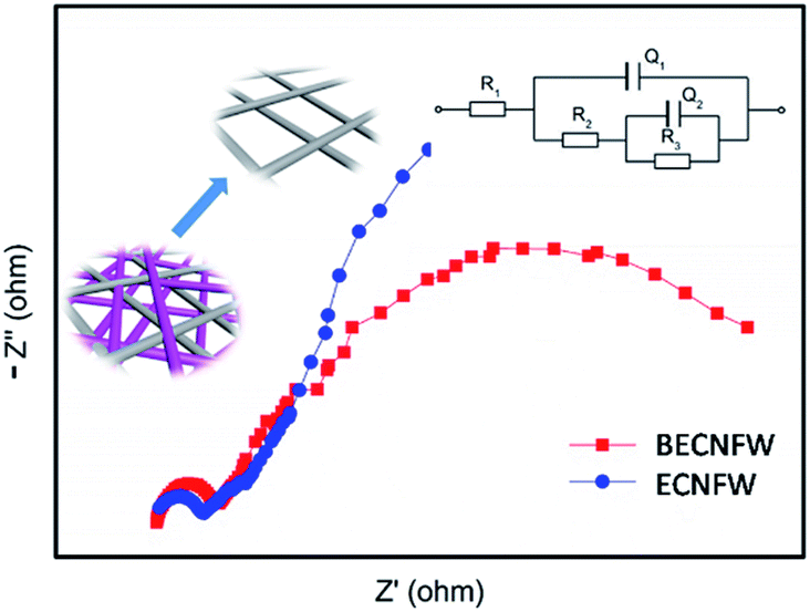 | ||
| Fig. 6 Nyquist plots of single cell with ECNFW and BECNFW. | ||
Conclusion
In conclusion, this work proposes a novel strategy to facilitate the application of carbon nano-fibrous materials in VFB. The self-standing carbon nano-fibrous web with ultra large pores and high porosity (BECNFW) was rationally designed and successfully synthesized for VFB via the horizontally-opposed blending electrospinning method. Compared with the traditional electrospinning carbon nanofibers web (ECNFW), BECNFW remains its self-standing property and possesses much higher porosity and larger pore sizes, which can be used as symmetric electrodes for VFB directly and further reduce the concentration polarization effectively. Though the electrocatalytic activity of O-groups and N-groups for vanadium redox pairs is impaired by the treatment of 10 wt% ethanol/water solution, the VFB with BECNFW electrodes still exhibits higher performances than that of VFB with ECNFW electrodes. The CE, VE and EE of the single cell reach as high as 95.4%, 81.6% and 77.9%, respectively, at 60 mA cm−2, while for VFB with ECNFW electrodes, the performances are reduced to 93.6%, 71.3% and 66.8%, respectively. The VE and EE of VFB single cell with BECNFW electrodes are even above 10% higher than those of the VFB with ECNFW electrodes. Besides, the utilization efficiency of electrolyte for BECNFW is approximately as twice as that of ECNFW due to the reduction of concentration polarization caused by BECNFW higher porosity and larger pore sizes. The results suggest that expanding the pore size could be one effective strategy to facilitate the carbon nano-fibrous materials' applications for VFB, and that BECNFW is a promising electrode candidate for VFB.Conflicts of interest
There are no conflicts to declare.Acknowledgements
The authors greatly acknowledge the financial support from China Natural Science Foundation (Grant No. 51361135701, 21206158 and 21476224) and the Outstanding Young Scientist Foundation, Chinese Academy of Sciences (CAS), Dalian Municipal Outstanding Young Talent Foundation (2014J11JH131).Notes and references
- W. Wang, Q. Luo, B. Li, X. Wei, L. Li and Z. Yang, Adv. Funct. Mater., 2013, 23, 970–986 CrossRef CAS.
- R. A. Huggins, J. Electrochem. Soc., 2017, 164, A5031–A5036 CrossRef CAS.
- C. P. De Leon, A. Frías-Ferrer, J. González-García, D. Szánto and F. C. Walsh, J. Power Sources, 2006, 160, 716–732 CrossRef.
- P. Leung, X. Li, C. Ponce de Leon, L. Berlouis, C. T. J. Low and F. C. Walsh, RSC Adv., 2012, 2, 10125–10156 RSC.
- Y. Zhao, Y. Ding, Y. Li, L. Peng, H. R. Byon, J. B. Goodenough and G. Yu, Chem. Soc. Rev., 2015, 44, 7968–7996 RSC.
- C. Ding, H. Zhang, X. Li, T. Liu and F. Xing, J. Phys. Chem. Lett., 2013, 4, 1281–1294 CrossRef CAS PubMed.
- L. Shi, S. Liu, Z. He, H. Yuan and J. Shen, Electrochim. Acta, 2015, 178, 748–757 CrossRef CAS.
- N. Pour, D. G. Kwabi, T. Carney, R. M. Darling, M. L. Perry and Y. Shao-Horn, J. Phys. Chem. C, 2015, 119, 5311–5318 CAS.
- A. Z. Weber, M. M. Mench, J. P. Meyers, P. N. Ross, J. T. Gostick and Q. Liu, J. Appl. Electrochem., 2011, 41, 1137–1164 CrossRef CAS.
- W. Li, J. Liu and C. Yan, Electrochim. Acta, 2011, 56, 5290–5294 CrossRef CAS.
- W. Li, J. Liu and C. Yan, J. Solid State Electrochem., 2013, 17, 1369–1376 CrossRef CAS.
- H. Liu, Q. Xu and C. Yan, Electrochem. Commun., 2013, 28, 58–62 CrossRef.
- S. Wang, X. Zhao, T. Cochell and A. Manthiram, J. Phys. Chem. Lett., 2012, 3, 2164–2167 CrossRef CAS PubMed.
- A. Parasuraman, T. M. Lim, C. Menictas and M. Skyllas-Kazacos, Electrochim. Acta, 2013, 101, 27–40 CrossRef CAS.
- Z. He, L. Dai, S. Liu, L. Wang and C. Li, Electrochim. Acta, 2015, 176, 1434–1440 CrossRef CAS.
- B. Li, M. Gu, Z. Nie, Y. Shao, Q. Luo, X. Wei, X. Li, J. Xiao, C. Wang, V. Sprenkle and W. Wang, Nano Lett., 2013, 13, 1330–1335 CrossRef CAS PubMed.
- W. Xie, H. Cheng, Z. Chu, Z. Chen and C. Long, Ceram. Int., 2011, 37, 1947–1951 CrossRef CAS.
- M. Skyllas-Kazacos, M. H. Chakrabarti, S. A. Hajimolana, F. S. Mjalli and M. Saleem, J. Electrochem. Soc., 2011, 158, R55 CrossRef CAS.
- H. Q. Zhu, Y. M. Zhang, L. Yue, W. S. Li, G. L. Li, D. Shu and H. Y. Chen, J. Power Sources, 2008, 184, 637–640 CrossRef CAS.
- J. Melke, P. Jakes, J. Langner, L. Riekehr, U. Kunz, Z. Zhao-Karger, A. Nefedov, H. Sezen, C. Wöll, H. Ehrenberg and C. Roth, Carbon, 2014, 78, 220–230 CrossRef CAS.
- C. Flox, M. Skoumal, J. Rubio-Garcia, T. Andreu and J. R. Morante, Appl. Energy, 2013, 109, 344–351 CrossRef CAS.
- C. Flox, J. Rubio-García, M. Skoumal, T. Andreu and J. R. Morante, Carbon, 2013, 60, 280–288 CrossRef CAS.
- H. Lee and H. Kim, J. Appl. Electrochem., 2013, 43, 553–557 CrossRef CAS.
- K. J. Kim, S. W. Lee, T. Yim, J. G. Kim, J. W. Choi, J. H. Kim, M. S. Park and Y. J. Kim, Sci. Rep., 2014, 4, 6906 CrossRef CAS PubMed.
- Y. Huang, J. Huo, S. Dou, K. Hu and S. Wang, RSC Adv., 2016, 6, 66368–66372 RSC.
- P. Han, X. Wang, L. Zhang, T. Wang, J. Yao, C. Huang, L. Gu and G. Cui, RSC Adv., 2014, 4, 20379–20381 RSC.
- C. Yao, H. Zhang, T. Liu, X. Li and Z. Liu, J. Power Sources, 2012, 218, 455–461 CrossRef CAS.
- K. J. Kim, M. S. Park, J. H. Kim, U. Hwang, N. J. Lee, G. Jeong and Y. J. Kim, Chem. Commun., 2012, 48, 5455–5457 RSC.
- G. Wei, J. Liu, H. Zhao and C. Yan, J. Power Sources, 2013, 241, 709–717 CrossRef CAS.
- G. Wei, X. Fan, J. Liu and C. Yan, J. Power Sources, 2014, 270, 634–645 CrossRef CAS.
- A. Fetyan, I. Derr, M. K. Kayarkatte, J. Langner, D. Bernsmeier, R. Kraehnert and C. Roth, ChemElectroChem, 2015, 2, 2055–2060 CrossRef CAS.
- S. Liu, M. Kok, Y. Kim, J. L. Barton, F. R. Brushett and J. Gostick, J. Electrochem. Soc., 2017, 164, A2038–A2048 CrossRef CAS.
- C. Alegre, C. Busacca, O. Di Blasi, V. Antonucci, A. S. Aricò, A. Di Blasi and V. Baglio, J. Power Sources, 2017, 364, 101–109 CrossRef CAS.
- C. Busacca, O. Di Blasi, N. Briguglio, M. Ferraro, V. Antonucci and A. Di Blasi, Electrochim. Acta, 2017, 230, 174–180 CrossRef CAS.
- A. Di Blasi, C. Busaccaa, O. Di Blasia, N. Briguglioa, G. Squadritoa and V. Antonuccia, Appl. Energy, 2017, 190, 165–171 CrossRef CAS.
- M. A. Abdelkareem, D. Takino, T. Ishikawa, T. Tsujiguchi and N. Nakagawa, Key Eng. Mater., 2012, 497, 73–79 CrossRef CAS.
- H. Katsura, T. Koyama, M. Ichikawa and Y. Taniguchi, Sen'i Gakkaishi, 2008, 64, 11–14 CrossRef CAS.
- C. Xu, X. Yang, X. Li, T. Liu and H. Zhang, J. Energy Chem., 2017, 26, 730–737 CrossRef.
- H. Kang, Y. Zhu, J. Shen, X. Yang, C. Chen, H. Cao and C. Li, Mater. Res. Bull., 2010, 45, 830–837 CrossRef CAS.
- X. Yu, H. Xiang, Y. Long, N. Zhao, X. Zhang and J. Xu, Mater. Lett., 2010, 64, 2407–2409 CrossRef CAS.
- J. Zheng, H. Zhang, Z. Zhao and C. C. Han, Polymer, 2012, 53, 546–554 CrossRef CAS.
- S. Moon, J. Choi and R. J. Farris, Fibers Polym., 2008, 9, 276 CrossRef CAS.
- G. Wei, X. Fan, J. Liu and C. Yan, J. Power Sources, 2015, 281, 1–6 CrossRef CAS.
- T. Liu, X. Li, C. Xu and H. Zhang, ACS Appl. Mater. Interfaces, 2017, 9, 4626–4633 CAS.
| This journal is © The Royal Society of Chemistry 2017 |