 Open Access Article
Alternating magnetic field mediated micro reaction system for palladium-catalyzed coupling reactions†
Hee Jae Kima,
Jinseop Choib,
Jaehoon Choec,
Kwang Ho Song *a and
Sunwoo Lee
 *b
*b
aDepartment of Chemical & Biological Engineering, Korea University, Seoul 02841, Republic of Korea. E-mail: khsong@korea.ac.kr
bDepartment of Chemistry, Chonnam National University, Gwangju, 61186, Republic of Korea. E-mail: sunwoo@chonnam.ac.kr
cLG Chem Research Park, Daejeon 34122, Republic of Korea
First published on 27th July 2017
Abstract
A continuous flow reaction system in which a palladium magnetic catalyst was immobilized and vibrated by an alternating induced magnetic field was developed. The alternating electromagnetic field improved the mixing efficiency and catalytic activity for the palladium-catalyzed coupling reactions. This flow reaction system showed good product yields for various reactions such as Sonogashira, Heck, Suzuki, Stille, Hiyama and decarboxylative coupling reactions.
Transition metal-catalyzed transformations are one of the most versatile synthetic tools in organic synthesis.1 In particular, coupling reactions catalyzed by late transition metals such as palladium, copper, and nickel have been widely used to construct important organic building blocks in pharmaceutical and materials chemistry.2 The development of palladium-catalyzed coupling reactions was awarded the Nobel Prize in Chemistry in 2010.3
The considerable attention paid to green chemistry has triggered a need to develop of environmentally friendly chemical processes. To meet this demand, recyclable catalytic systems with immobilized catalysts have been developed for organic transformations that proceed via homogeneous catalysis.4 The most common method for immobilization of catalysts uses polymer or inorganic supports bearing ligands that can bind to the metal catalyst. To make the process for recycling the catalyst easier, magnetic particles were employed and encapsulated by the immobilized catalyst.5
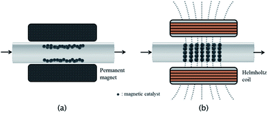
The continuous flow reaction system has been developed and applied to a variety of transition metal-catalyzed transformations.6 Compared with traditional batch reactions, this continuous flow chemistry has several benefits, including excellent mass transfer and thermal control due to the high surface-to-volume area. Moreover, continuous flow systems can be easily scaled by using parallel reactors. To apply this continuous flow reaction system in metal-catalyzed transformations, the most important factor is the immobilization of catalyst on the flow reactor. Most cases have borrowed tools that were established in batch reaction systems. One of the most frequently used methods is the immobilization of the catalyst on polymer or inorganic supports packed in the channel of the flow reactor.7 However, this catalytic packing system gave rise to a backpressure owing to the high volume of supporting materials. As a solution to solve this problem, the immobilization of the catalyst on magnetic particles was employed in the reaction flow system (Fig. 1a).8 However, with this method, only a small portion of the reagents might encounter the catalyst particles, and the efficiency of the reaction is very low because the catalyst is immobilized on the surface of the channel by a magnetic field.
To address these issues, we introduced an alternating magnetic field into the continuous flow reaction system with palladium magnetic particles as an immobilized catalyst. In addition, to arrange and vibrate the catalyst in the reaction channel, the induced magnetic field was periodically changed to improve the mixing efficiency. For microfluidic systems, some simulations have been reported for magnetic particles in an induced magnetic field and showed improved mixing efficiency for electromagnetic micro reactors. Here, we report the continuous flow reactions using an immobilized magnetic palladium catalyst under an induced magnetic field (Fig. 1b).
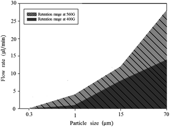
To achieve our goal, we attempted to optimize conditions such as catalyst particle size, flow rate, and strength and frequency of the magnetic field. It is important to find conditions under which the catalyst particles stay in the reaction channel with the appropriate flow rate without loss of particles. To determine the optimal particle size and flow rate, we chose four different sizes of magnetic palladium particles and investigated the relationship between particle size, magnetic field strength, and flow rate of the reaction mass. As most of the catalyst particle consists of iron oxide, the size of the catalyst particles was controlled by using iron oxides of different sizes. The same amount of magnetic particles to each four different sizes injected to 1/16 inch channel. It tested whether magnetic particles are spilled out from the channel in the condition of 400 G and 560 G at various flow rates. As shown in Fig. 2, 0.3 and 1 μm particles did not stay in the reaction channel under flow rates in the range of 4–30 μL min−1 in either 400 or 560 G magnetic fields. The 15 μm particles were retained in the reaction channel under a flow rate of 12 μL min−1 in a 560 G magnetic field. The 70 μm particles did not stay in the reaction channel under a flow rate of 28 μL min−1. When the flow rate was decreased to 20 μL min−1, the 70 μm particles were retained in the reaction channel in a 560 G magnetic field, but not in a 400 G magnetic field. However, the 70 μm particles were retained at a flow rate of 14 μL min−1 in both 400 and 560 G magnetic fields. In retention range of Fig. 2, we found that this flow system hold 98% of the catalyst during 1.5 h.
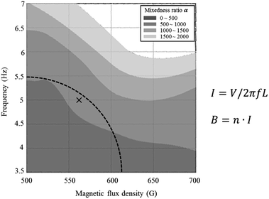
From the above experiment, a magnetic field of at least 560 G is required to retain 15 μm in the reaction channel. We conducted a Villermaux–Dushman reaction.9,10 to observe the change in mixing efficiency of the electromagnetic microreactor at various magnetic fields and frequencies. The results of the Villermaux–Dushman reaction experiment, as shown in Fig. 3, indicate that magnetic particles move more at high frequencies than at low frequencies and move further at high intensities than at low intensities. For the Helmholtz coil, the magnitude of magnetic flux density and frequency are inversely proportional area. Equations that show the relation of the magnitude of magnetic flux density and the frequency are displayed in Fig. 3. Accordingly, the experiment had to be conducted in a fan-shaped. In this area, we chose the condition that has better mixedness ratio than the darker area, and carried out the experiments in the condition of marked point (5 Hz, 560 G).
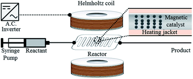
With this result in hand, we chose to use 15 μm magnetic particles to prepare the magnetic palladium catalyst using a well-established method.11 These magnetic catalyst particles were packed in a flow reaction tube, which was placed in a Helmholtz coil, as shown Fig. 4.
To evaluate the magnetic flow reaction system, Sonogashira coupling reaction was tested using flow reaction systems with either permanent magnet or the Helmholtz coil. As shown in Table 1, phenylacetylene and iodobenzene were reacted under a variety of conditions. With increasing temperature, the product yields were increased in both cases (entries 1–3). As expected, the Helmholtz coil system showed higher yields than the permanent magnet system. With organic bases such as Et3N and DBU, the Helmholtz coil system afforded the desired product, but no desired product was formed using the permanent magnet system (entries 4 and 5).
| Entry | Temp (°C) | Based | Yieldb (%) | Yieldb,c (%) |
|---|---|---|---|---|
| a Reaction condition: iodobenzene (0.1 mmol), phenylacetylene (0.12 mmol), base (0.2 mmol) were dissolved in DMF (dimethylformamide, 20 mL). Magnetic catalyst (0.125 mol% based on Pd); flow rate: 12 μL min−1; residence time: 90 min.b Yield of diphenyl acetylene was determined by gas chromatography analysis.c Yield of diphenyl acetylene under permanent magnet field.d Base: TBAF = tetrabutylammonium fluoride; TEA = triethylamine; DBU = [1,8-diazabicyclo-5.4.0]undec-7-ene. | ||||
| 1 | 90 | TBAF | 66 | — |
| 2 | 110 | TBAF | 82 | 11 |
| 3 | 130 | TBAF | 89 | 12 |
| 4 | 110 | TEA | 77 | — |
| 5 | 130 | DBU | 77 | — |
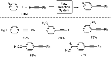
Using this condition, various aryl iodides were employed in this flow reaction system. As shown in Scheme 1, iodotoluenes underwent this reaction with good products. Aryl iodides bearing electron-donating and electron-withdrawing groups also afforded the desired products in good yields.
To expand this flow reaction system, a variety of coupling reactions were employed (Table 2). Heck reaction provided the desired product with 85% yield (entry 1). Suzuki, Stille and Hiyama coupling reactions afforded 4-methylbiphenyl with 74%, 87% and 95% yields, respectively (entries 2–4). In addition, a decarboxylative coupling reaction with phenyl propiolic acid gave diphenyl acetylene with 85% yield (entry 5).12
| Entry | Reactant 1/reactant 2 | Base | Product | Yieldb (%) |
|---|---|---|---|---|
| a Reaction conditions: reactant 1 (0.1 mmol), reactant 2 (0.12 mmol), and base (0.2 mmol) were dissolved in DMF (20 mL) and flowed. Magnetic catalyst (0.125 mol% based on Pd); flow rate: 12 μL min−1; residence time: 90 min.b Yields were determined by gas chromatography. | ||||
| 1 | C6H5I/CH2CHCO2(n-Bu) | Et3N |  |
85 |
| 2 | 4-MeC6H4I/C6H5B(OH)2 | Et3N |  |
74 |
| 3 | 4-MeC6H4I/C6H5SnBu3 | — |  |
87 |
| 4 | 4-MeC6H4I/C6H5Si(OEt)3 | TBAF |  |
95 |
| 5 | C6H5I/C6H5CCCO2H | TBAF |  |
85 |
In summary, we developed a flow reaction system in which immobilized palladium magnetic particles act as a catalyst in an electromagnetic microreactor using a Helmholtz coil with alternating current. We studied the relationship between magnetic particle size, flow rate, and strength of magnetic field to find optimized conditions (>15 μm, 12 μL min−1, and 560 G). This flow reaction system showed good catalytic activities for palladium-catalyzed coupling reactions such as Sonogashira, Heck, Suzuki, Stille, Hiyama and decarboxylative coupling reactions. In addition, all reactions could be scalable by using parallel reactors.
Acknowledgements
This research was supported by the National Research Foundation of Korea (NRF) grant funded by the Korea government (NRF-2012R1A1A2044286 and NRF-2015R1A4A1041036).Notes and references
- (a) L. Haughton and J. M. J. Williams, J. Chem. Soc., 1999, 1, 2645 Search PubMed; (b) B. C. G. Soderberg, Coord. Chem. Rev., 2003, 247, 79 CrossRef CAS.
- (a) A. Brennfuhrer, H. Neumann and M. Beller, Angew. Chem., Int. Ed., 2009, 48, 4114 CrossRef PubMed; (b) R. Martin and S. L. Buchwald, Acc. Chem. Res., 2008, 41, 1461 CrossRef CAS PubMed.
- C. C. C. J. Seechurn, M. O. Kitching, T. J. Colacot and V. Snieckus, Angew. Chem., Int. Ed., 2012, 51, 5062 CrossRef PubMed.
- (a) B. M. Trost, Angew. Chem., Int. Ed., 1995, 34, 259 CrossRef CAS; (b) I. Angurell, G. Muller, M. Rocamora, O. Rossell and M. Seco, Dalton Trans., 2003, 6, 1194 RSC; (c) B. C. Ranu, S. Bhadra and D. Saha, Curr. Org. Synth., 2011, 8, 146 CrossRef CAS; (d) N. Nami and N. Nami, J. Chem., Biol. Phys. Sci., 2015, 5, 1195 CAS.
- (a) D. Astruc, F. Lu and J. R. Aranzaes, Angew. Chem., Int. Ed., 2005, 44, 7852 CrossRef CAS PubMed; (b) R. B. Bedford, M. Betham, D. W. Bruce, S. A. Davis, R. M. Frost and M. Hird, Chem. Commun., 2006, 13, 1398 RSC; (c) C. P. Park and D. P. Kim, Angew. Chem., Int. Ed., 2010, 49, 6825 CrossRef CAS PubMed; (d) P. Li, L. Wang, L. Zhang and G.-W. Wang, Adv. Synth. Catal., 2012, 354, 1307 CrossRef CAS; (e) L. Zhang, P. Li, J. Yang, M. Wang and L. Wang, ChemPlusChem, 2014, 79, 217 CrossRef CAS; (f) L. Zhang, P. Li, H. Li and L. Wang, Catal. Sci. Technol., 2012, 2, 1859 RSC.
- (a) A. Nagaki, A. Kenmoku, Y. Moriwaki, A. Hayashi and J. I. Yoshida, Angew. Chem., Int. Ed., 2010, 49, 7543 CrossRef CAS PubMed; (b) J. P. McMullen, M. T. Stone, S. L. Buchwald and K. F. Jensen, Angew. Chem., Int. Ed., 2010, 49, 7076 CrossRef CAS PubMed; (c) T. Noël, S. Kuhn, A. J. Musacchio, K. F. Jensen and S. L. Buchwald, Angew. Chem., Int. Ed., 2011, 50, 6065 CrossRef; (d) T. Noël, J. R. Naber, R. L. Hartman, J. P. McMullen, K. F. Jensen and S. L. Buchwald, Chem. Sci., 2011, 2, 287 RSC; (e) D. Obermayer, A. M. Balu, A. A. Romero, W. Goessler, R. Luque and C. O. Kapper, Green Chem., 2013, 15, 1530 RSC; (f) D. Cantillo and C. O. Kappe, ChemCatChem, 2014, 6, 3286 CrossRef CAS; (g) R. Munirathhinam, J. Huskens and W. Verboom, Adv. Synth. Catal., 2015, 357, 1093 CrossRef; (h) M. Brzozowski, J. A. Forni, G. P. Savage and A. Polyzos, Chem. Commun., 2015, 51, 334 RSC; (i) H. Lebel, H. Piras and M. Borduy, ACS Catal., 2016, 6, 1109 CrossRef CAS.
- (a) C. G. Chang, B. K. Paul, V. T. Remcho, S. Atre and J. E. Hutchison, J. Nanopart. Res., 2008, 10, 965 CrossRef CAS; (b) U. Laska, C. G. Frost, G. J. Price and P. K. Plucinski, J. Catal., 2009, 268, 318 CrossRef CAS; (c) N. J. S. Costa, P. K. Kiyohara, A. L. Monteiro, Y. Coppel, K. Philippot and L. M. Rossi, J. Catal., 2010, 276, 382 CrossRef CAS; (d) X. Zhang, P. Li, Y. Ji, L. Zhang and L. Wang, Synthesis, 2011, 18, 2975 Search PubMed; (e) K. Terao, Y. Nishiyama, H. Tanimoto, T. Morimoto, M. Oelgemoller and K. Kakiuchi, J. Flow Chem., 2012, 2, 73 CrossRef CAS; (f) L. B. Escudero, R. A. olsina and R. G. Wuilloud, Talanta, 2013, 116, 133 CrossRef CAS PubMed; (g) D. Cantillo and C. O. Kappe, ChemCatChem, 2016, 6, 3286 CrossRef.
- (a) M. N. Moore, M. Andrade, A. N. Scozzari and A. H. Krotz, Org. Process Res. Dev., 2004, 8, 271 CrossRef CAS; (b) E. V. Alonso, M. D. M. Guerrero, P. C. Cueto, J. B. Benitez, J. M. C. Pavon and A. G. D. Torres, Talanta, 2016, 153, 228 CrossRef PubMed.
- J. M. Commenge and L. Falk, Chem. Eng. Proc., 2011, 50, 979 CrossRef CAS.
- See ESI (S1†) for the detailed process of Villermaux–Dushman reaction.
- See ESI (S2†) for the detailed synthetic procedure fo catalytic magnetic particle.
- (a) J. Moon, M. Jeong, H. Nam, J. Ju, J. H. Moon, H. M. Jung and S. Lee, Org. Lett., 2008, 10, 945 CrossRef CAS PubMed; (b) J. Moon, M. Jang and S. Lee, J. Org. Chem., 2009, 74, 1403 CrossRef CAS PubMed; (c) H. Kim and P. H. Lee, Adv. Synth. Catal., 2009, 351, 2827 CrossRef CAS; (d) K. Park and S. Lee, RSC Adv., 2013, 3, 14165 RSC.
Footnote |
| † Electronic supplementary information (ESI) available. See DOI: 10.1039/c7ra07324k |
| This journal is © The Royal Society of Chemistry 2017 |

