 Open Access Article
Creative Commons Attribution 3.0 Unported Licence
Preparation and optical properties of magnetic carbon/iron oxide hybrid dots
Yin Huab,
Ping Wangb,
Christopher E. Bunkerc,
Lindsay R. Teislb,
McIver Reiboldb,
Sijia Yanb,
Haijun Qianb,
Dawei Hea and
Ya-Ping Sun *b
*b
aKey Laboratory of Luminescence and Optical Information, Ministry of Education, Institute of Optoelectronic Technology, Beijing Jiaotong University, Beijing 100044, China
bDepartment of Chemistry and Laboratory for Emerging Materials and Technology, Clemson University, Clemson, South Carolina 29634-0973, USA. E-mail: syaping@clemson.edu
cPropulsion Directorate, Air Force Research Laboratory, Wright-Patterson Air Force Base, Ohio 45433, USA
First published on 23rd August 2017
Abstract
Carbon dots (CDots), generally defined as small carbon nanoparticles with various surface passivation schemes for bright and colorful fluorescence emissions, have emerged to represent a rapidly advancing and expanding research field. Building upon the basic structural configuration of CDots, iron oxides were introduced for both magnetic and fluorescence properties in the resulting hybrid dots, thus resulting in more capabilities beyond those of neat CDots. The carbon/Fe3O4 hybrid dots with oligomeric polyethylene glycol or polyethyleneimine for surface functionalization and passivation were prepared in a facile thermal carbonization synthesis using microwave energy, coupled with magnetic separation. The magnetic hybrid dots were fluorescent over the visible spectrum, but the fluorescence quantum yields were found to be lower than those of their neat CDots counterparts, for which a possible quenching effect due to the Fe3O4 in the dot structure was probed and evaluated. The results support the notion that the hybrid dot configuration could serve as a platform for imparting magnetic properties into brightly fluorescent CDots. Also investigated were the dot structures and compositions to gain a rough view of the carbon–iron oxide configurations in the hybrid dots. The application potential of the hybrid dots and opportunities for their further improvements are discussed.
1. Introduction
Carbon is commonly perceived as being a dark-colored matter, with little attention paid to its optical properties other than its use as a blackbody for photon to heat conversion. At the nanoscale, however, carbon materials have exhibited rich optical properties, including effective photon harvesting to drive excited state energy and charge transfer processes, which are widely pursued for a variety of applications.1–3 Especially, carbon “quantum” dots or carbon dots (CDots, Fig. 1)4 have emerged to represent a new class of carbon-based optical nanomaterials with bright and colorful fluorescence emissions, attracting much attention recently.5–13 In fact, the investigation on the science and technology of CDots has become a rapidly advancing and expanding research field, as made evident by the large number of publications in the literature.12,13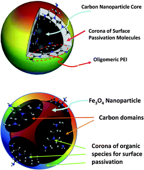 | ||
| Fig. 1 A cartoon illustration on a CDot with polyethyleneimine (PEI) for surface functionalization (upper)45 and a carbon/Fe3O4 hybrid dot with organic species for the desired passivation effect (lower). | ||
CDots are generally defined as small carbon nanoparticles with various surface passivation schemes, among which the use of organic molecules or species has been effective (Fig. 1).4,14,15 Beyond the neat CDots, the same structural configuration, along with some of the synthesis methods for CDots, has been used as the basis for carbon-based hybrid nanostructures with semiconductors including TiO2 and others for purposes such as much improved optical properties16,17 and enhanced photocatalytic activities.18–22 Similarly, unpaired electrons have been introduced into the structure of CDots to impart magnetic properties in the resulting hybrid nanostructures, with far-reaching implications in terms of an understanding of the effects and/or interactions between the optical and magnetic properties and in the expanded development of CDots-derived technologies.23–32 For example, Du, et al. fabricated Gd-doped CDots by hydrothermal treatment of a mixture of glycine and gadopentetic acid, and found that these dots could serve as T1 contrast agents in magnetic imaging, exhibiting also the dose enhancement effect in inhibiting the growth of solid tumor.30 Han, et al. used the solvothermal reaction of MnCl2, EDTA, and triethylenetetramine in ethylene glycol for the preparation of Mn-doped CDots, and evaluated the dots thus prepared in MRI-fluorescence dual-modality bioimaging.28 In a similar solvothermal synthesis, Wang, et al. prepared porous carbon/Fe3O4 hybrid nanoparticles of large sizes (around 100 nm in diameter) for their serving as vehicles to carry anti-cancer drug doxorubicin and for the function of light-controlled drug release.32
In fact, carbon/metal oxide hybrid dots may represent a versatile platform for combining optical properties with magnetic and other functionalities, alternative to the widely pursued strategies such as incorporating fluorescent dye molecules, noble metal nanoparticles, and/or semiconductor quantum dots into polymeric or silica composite nanospheres.32,33 For those materials, a significant amount of results have been reported in the literature on their various promising potential applications, such as biomedical imaging, drug delivery and controlled release, and other uses.34–39 Among a few available studies of nanoscale Fe3O4 as the metal oxide in hybrid dots involving carbon, Li, et al. fabricated carbon/Fe3O4 nanoparticles of relatively small sizes for their uses in cell imaging by both magnetic and fluorescence modalities, though the optical excitation and fluorescence emissions of these nanoparticles were mostly limited to the UV spectral region.33
In this work, carbon/Fe3O4 hybrid dots with oligomeric polyethylene glycol (PEG) or polyethyleneimine (PEI) for surface functionalization and passivation were prepared in a facile synthesis based on thermal carbonization with microwave energy, coupled with magnetic separation. The hybrid dots were characterized for an understanding of their structures and compositions, with the results suggesting that the hybrid dot structure may be viewed as a relatively small Fe3O4 nanoparticle decorated with carbon moieties in very roughly a core–shell like configuration, functionalized by the organic species (Fig. 1). Optical absorption and fluorescence properties of the hybrid dots were compared with those of their neat CDots counterparts, and an emphasis of the investigation was on probing any quenching effect of the Fe3O4 on the fluorescence properties of the passivated carbon domains in the hybrid dots. The potential and also challenges in the development of magnetic carbon/metal oxide hybrid dots with high optical performance (bright and colorful fluorescence emissions in particular) are highlighted and discussed.
2. Experimental section
2.1 Materials
Ferric ammonium citrate (C6H8O7·xFe3+·yNH3) was purchased from VWR, ferrous sulfate heptahydrate (FeSO4·7H2O) from J. T. Baker, and potassium thiocyanate (KSCN) from Strem Chemicals, Inc. Oligomeric polyethylene glycol (PEG1500, average molecular weight ∼ 1500) was obtained from ACROS Organics, polyethylenimine (PEI, branched, average molecular weight ∼ 1200) from Polyscience, Inc., and polyvinylpyrrolidone (PVP, average molecular weight ∼ 40![[thin space (1/6-em)]](https://www.rsc.org/images/entities/char_2009.gif) 000) from Sigma Aldrich. Silicon carbide (120 grit) was acquired from Panadyne Abrasives, nitric acid and sulfuric acid from Fisher Chemical, and potassium permanganate from ACROS. Dialysis membrane tubings (molecular weight cut-off ∼500 and ∼1000) were supplied by Spectrum Laboratories. Water was deionized and purified by being passed through a Labconco WaterPros water purification system.
000) from Sigma Aldrich. Silicon carbide (120 grit) was acquired from Panadyne Abrasives, nitric acid and sulfuric acid from Fisher Chemical, and potassium permanganate from ACROS. Dialysis membrane tubings (molecular weight cut-off ∼500 and ∼1000) were supplied by Spectrum Laboratories. Water was deionized and purified by being passed through a Labconco WaterPros water purification system.
2.2 Measurements
Powder X-ray diffraction measurements were performed on a Rigaku Ultima IV X-ray diffractometer with Cu Kα radiation (λ = 1.5418 Å) at 25 °C. The calculation of crystallite sizes based on the Scherrer equation was enabled by the PDXL 1.8.1.0 software. The transmission electron microscopy (TEM) imaging was carried out on a Hitachi H-9500 high-resolution TEM system. The TEM specimen was prepared by depositing a few drops of a dilute sample solution onto a copper grid, followed by careful evaporation to remove the solvent. UV/vis absorption spectra were recorded on a Shimadzu UV2501-PC spectrophotometer. Fluorescence spectra were acquired on a Jobin-Yvon emission spectrometer equipped with a 450 W xenon source, Gemini-180 excitation and Triax-550 emission monochromators, and a photon counting detector (Hamamatsu R928P PMT at 950 V). 9,10-Bis(phenylethynyl)-anthracene in cyclohexane was used as a standard in the determination of fluorescence quantum yields by the relative method (matching the absorbance at the excitation wavelength between the sample and standard solutions and comparing their corresponding integrated total fluorescence intensities). FT-IR spectra were measured on a Shimadzu IRAffinity-1S spectrophotometer with the Single Reflection ATR accessory for solid samples.2.3 PEGylated carbon/Fe3O4 hybrid dots
Ferric ammonium citrate (0.5 g) and PEG1500 (1 g) were mixed in water (10 mL) in a small scintillation vial with stirring to yield a brown-colored solution, followed by the removal of water via purging with nitrogen gas for the reactant mixture. Separately, a silica crucible casting dish (about 8 cm in diameter and 2.5 cm in height) containing silicon carbide (150 g) was pre-heated in a conventional microwave oven at 500 W for 3 min. The small scintillation vial containing the reactant mixture was immersed in the pre-heated silicon carbide bath for processing in the same microwave oven. The initial treatment was at 1000 W until smoke started to appear (after about half min). The oven was opened, and the vial containing the mixture was taken out of the silicon carbide bath to be in the ambient for about 1 min. Then, the vial was re-immersed in the silicon carbide bath for a repeat of the same cycle of microwave treatment until smoke appearing and then out in the ambient for about 1 min. After a total of 7 treatment cycles, the reaction mixture was collected and cooled to the ambient temperature, and then dispersed in deionized water (10 mL) with vigorous sonication. The resulting aqueous dispersion was allowed to stand for about 10 min before the separation in a magnetic separator (Dynal MPC-L). For the separation, the aqueous dispersion of the reaction mixture was in the separator for about 2 h. The supernatant was removed, and the magnetic precipitate was washed with water and precipitated again in the magnetic separator. After the repeated washing until the supernatant became colorless, the final magnetic precipitate was collected as the as-prepared sample of the PEGylated carbon/Fe3O4 hybrid dots (PEG-C/Fe3O4-dots).2.4 Polyethylenimine-functionalized carbon/Fe3O4 hybrid dots
Ferric ammonium citrate (0.5 g) and polyethylenimine (PEI, 1 g) were mixed in water (10 mL) in a small scintillation vial with stirring to yield a brown-colored solution, followed by the removal of water via purging with nitrogen gas for the reactant mixture. Separately, a silica crucible casting dish (about 8 cm in diameter and 2.5 cm in height) containing silicon carbide (150 g) was pre-heated in a conventional microwave oven at 500 W for 3 min. The small scintillation vial containing the reactant mixture was immersed in the pre-heated silicon carbide bath for processing in the same microwave oven. The processing was in multiple cycles, each of which consisted of the treatment by microwave at 400 W until smoke started to appear in the sample vial, taking the vial out of the silicon carbide bath to be in the ambient for about 1 min, and then re-immersing the vial in the silicon carbide bath for the next cycle. After a total of 12, the reaction mixture was collected and cooled to the ambient temperature, and then dispersed in deionized water (10 mL) with vigorous sonication. The resulting aqueous dispersion was allowed to stand for about 10 min before the magnetic separation by using the same protocol described above to collect the final magnetic precipitate as the as-prepared sample of the PEI-functionalized carbon/Fe3O4 hybrid dots (PEI-C/Fe3O4-dots).2.5 Iron content and removal
Iron contents in the hybrid dots were quantified by using the classical colorimetric method with the use of a thiocyanate agent for the formation of red-colored iron(III) complex. For the standard curve, an aqueous solution of FeSO4·7H2O (0.24895 g in 50 mL) was prepared, and to the solution was added concentrated H2SO4 (2.5 mL) and then aqueous KMnO4 (2%) dropwise until the purple color in the solution stopped fading. The resulting solution was diluted to 500 mL as the standard stock solution. An aliquot of the standard stock solution (10 mL) was diluted to 100 mL as the standard working solution. Five 25 mL volumetric flasks were used, to which different volumes of the working solution (0, 0.5, 1.0, 2.0, and 3.0 mL) were added, and then water (5 mL), H2SO4 (50%, 1 mL), KMnO4 (1%, 20 μL), and KSCN (20%, 2 mL) were added to each flask, followed by the dilution with water to the full volume of each flask (25 mL). The absorbances of the solutions at 470 nm were measured for the standard curve.For the digestion before the colorimetric analysis, a dot sample was refluxed in HNO3 (20%, 25 mL) for 2 h, and then the solution was concentrated to less than 10 mL in volume, followed by being cooled to room temperature and diluted to 10 mL for the working solution of the sample. The working solution (2 mL) was added to a 25 mL volumetric flask, and to the flask were then added water (5 mL), H2SO4 (50%, 1 mL), KMnO4 (1%, 20 μL) and KSCN (20%, 2 mL), followed by the dilution with water to the full volume of the flask (25 mL). The absorbance of the solution at 470 nm was measured, and the iron content in the sample was obtained from the standard curve.
For the removal of Fe3O4 from the hybrid dots, a dot sample in aqueous dispersion (2 mL) was mixed with HCl (20%, 25 mL), and the mixture was refluxed for 30 min. The reaction mixture was cooled back to ambient temperature, and dialyzed (molecular weight cutoff ∼ 500) against fresh water for 12 h. The solution in the dialysis tubing was collected and concentrated for characterization and investigations.
3. Results and discussion
The PEGylated hybrid dots PEG-C/Fe3O4-dots were prepared in the one-pot thermal carbonization processing of precursor mixtures containing oligomeric PEGs (PEG1500) and ferric ammonium citrate (FAC) in various PEG/FAC mass ratios. Different processing conditions involving the use of microwave irradiation for the thermal carbonization were evaluated, including various combinations of microwave power and irradiation time duration in a single treatment and the use of multiple treatment cycles, each of which consisted of microwave heating and then a quick cooling in the ambient. The reaction mixture from each processing was dispersed in water, and the resulting aqueous dispersion was separated in terms of magnetic precipitation in a magnetic separator with a permanent magnet to harvest the magnetically responsive fraction. The evaluation of the outcomes associated with different PEG/FAC mass ratios and thermal carbonization conditions was based on parameters including the product yield for the dot sample, the aqueous dispersibility, and the C/Fe ratio in the sample from the magnetic separation. The use of a PEG/FAC ratio of 2 in the precursor mixture coupled with multiple-cycle microwave treatments was identified as being more desirable for the carbonization processing. Briefly on the multiple treatment cycles for the thermal carbonization with microwave irradiation, in the initial cycle the precursor FAC–PEG mixture was immersed in a pre-heated silicon carbide bath for heating in a conventional microwave oven until the onset of visible smoking in the sample vial, and then the vial was taken out of the oven for a quick cooling in the ambient, followed immediately by the next treatment cycle of the same microwave irradiation and quick cooling. At the conclusion of the thermal carbonization processing, the targeted hybrid dots PEG-C/Fe3O4-dots could readily be harvested as the magnetically responsive fraction in the magnetic separation of the reaction mixture.Similarly, the PEI-functionalized hybrid dots PEI-C/Fe3O4-dots were prepared by thermal carbonization processing of FAC–PEI mixtures in terms of the same multiple microwave treatment – quick cooling cycles, and isolated from the reaction mixture as the magnetically responsive fraction in a magnetic separation.
Powder X-ray diffraction measurements were used for the characterization of the hybrid dots, and the diffraction patterns were found to be due exclusively to Fe3O4 (Fig. 2), suggesting that the samples were free from any meaningful presence of other crystalline species, and the carbon domains in the hybrid dots were largely amorphous, as commonly observed for core carbon nanoparticles in CDots.3,40–42 All of the diffraction peaks (2θ of 111, 220, 311, 400, 422, 511, and 440, Fig. 2) were broadened, consistent with the nanoscale nature of the Fe3O4 in the hybrid dots. With the peak broadening, calculations based on the Scherrer equation yielded average Fe3O4 nanocrystal sizes of 10 ± 1 nm and 9.5 ± 0.9 nm in the PEG-C/Fe3O4-dots and PEI-C/Fe3O4-dots, respectively. The size estimates were supported by the TEM imaging results. Shown in Fig. 3 is a representative TEM image for the PEI-C/Fe3O4-dots. Because of the high Z-contrast between carbon and iron, the size profiles in TEM images are dominated by the Fe3O4 nanoparticles in the hybrid dots. The statistical analysis based on multiple TEM images yielded an average size of 9.7 nm and a size distribution standard deviation of about 2 nm (Fig. 3), consistent with the estimate based on the Scherrer equation.
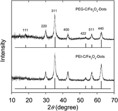 | ||
| Fig. 2 Results from the X-ray powder diffraction characterization of the hybrid dots, with the standard diffraction pattern of cubic Fe3O4 also shown for comparison. | ||
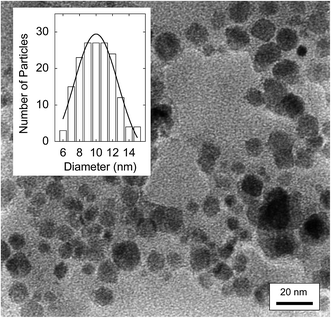 | ||
| Fig. 3 A TEM image of the PEI-C/Fe3O4-dots, with a statistical size analysis based on multiple images in the inset. | ||
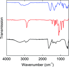
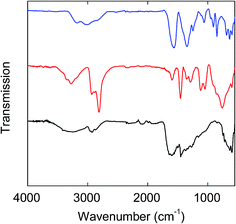
FT-IR spectra of the PEG-C/Fe3O4-dots and PEI-C/Fe3O4-dots are compared with those of the precursors (FAC, PEG1500, and the PEI) in Fig. 4 & 5. Overall, the spectra of the hybrid dots are apparently broadened, and both exhibit significant absorptions at 1770–1650 cm−1 due to carbonyl moieties, which are shifted from the carbonyl absorptions at 1650–1500 cm−1 in the spectrum of FAC (Fig. 4 & 5). As known in the literature,43,44 the strong carbonyl absorptions in neat citric acid are at 1770–1650 cm−1, and in FAC as a salt of citric acid with Fe(III), the absorptions of iron carboxylate are at 1650–1500 cm−1. Thus, the thermal processing for the formation of the hybrid dots must have sacrificed the iron carboxylate in the precursor FAC to have some of the resulting citric acid-like species bound and/or trapped in the hybrid dot structures. For the PEG-C/Fe3O4-dots, the characteristic C–H absorptions at 2900–2700 cm−1 are much weaker than those in neat PEG1500, largely as expected for the PEGs being consumed in the carbonization processing. Similarly weakened C–H absorptions are found in the spectrum of the PEI-C/Fe3O4-dots. For both hybrid dots, the broad absorption bands at low frequencies (630–590 cm−1, Fig. 4 & 5) may be assigned to Fe–O bonds.
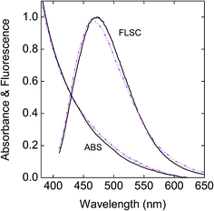
Aqueous dispersions of the hybrid dots exhibited more scattering in appearance visually and also in absorption spectral measurements even when the dispersions were very dilute, different from the solutions of neat CDots of similar surface functionalities reported previously.45 This might be due to several factors, including more significantly these hybrid dots being larger in size and heavier with a substantial content of Fe3O4. A commonly used strategy in improving the dispersion of inorganic and other nanoparticles46,47 was adopted by adding polyvinylpyrrolidone (PVP) polymers into the aqueous dispersions of the hybrid dots for reducing the light scattering in UV/vis absorption measurements. As shown in Fig. 6, the observed absorption spectra of the aqueous dispersed PEG-C/Fe3O4-dots and PEI-C/Fe3O4-dots with PVP polymers for improved dispersion are generally similar to that of the neat PEI-CDots reported previously.45 It should be pointed out that Fe3O4 nanoparticles are colored, but their absorptivities in the visible spectral region are generally low,48,49 and thus their contributions to the observed absorption spectra of the hybrid dots are insignificant.
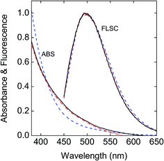 | ||
Fig. 6 Absorption (ABS) and fluorescence (FLSC, 440 nm excitation) spectra of the PEG-C/Fe3O4-dots ( ) and the PEI-C/Fe3O4-dots ( ) and the PEI-C/Fe3O4-dots ( ) in aqueous dispersions with PVP polymer as a dispersion agent are compared with those of the neat PEI-CDots in aqueous solution ( ) in aqueous dispersions with PVP polymer as a dispersion agent are compared with those of the neat PEI-CDots in aqueous solution ( ).45 ).45 | ||
Fluorescence spectra of the aqueous dispersed PEG-C/Fe3O4-dots and PEI-C/Fe3O4-dots are similar in profile to those of neat CDots, as illustrated in Fig. 6 for the comparison with the spectrum of neat PEI-CDots in aqueous solution, but their intensities or fluorescence quantum yields are lower. Between the two hybrid dots, the PEI-C/Fe3O4-dots are significantly more fluorescent, consistent with the general observation in the literature that CDots of surface functionalization by amino molecules or polymers are higher in fluorescence quantum yields.14,15,50 Nevertheless, the observed quantum yields of the PEI-C/Fe3O4-dots, on the order of 3% at 400 nm excitation, are still lower than those of the neat PEI-CDots (on average around 15% at the same excitation wavelength).45 Since the optical absorptions and fluorescence emissions in the visible spectral region are associated with the carbon domains in the hybrid dots, the observed lower fluorescence yields could be attributed to causes including the different formation processes and structural configurations of the hybrid dots from those of their neat CDots counterparts (resulting in less effective passivation of the carbon domains) and/or direct quenching effect of the Fe3O4 in the hybrid dots on the emissive excited states of the carbon domains. The latter as a possible cause was examined experimentally by removing Fe3O4 from the PEI-C/Fe3O4-dots, for which the dot sample was treated in an aqueous acid (HCl) solution to dissolve the iron oxide, followed by dialysis to harvest the residual nanostructures of the hybrid dots without the Fe3O4 nanoparticles. For these Fe3O4-free residual “dots”, their observed fluorescence spectra are largely the same as those of the original PEI-C/Fe3O4-dots before the acid treatment (Fig. 7), again supporting the conclusion that the fluorescence emissions in the hybrid dots are due to the carbon domains passivated by the organic species. The fluorescence quantum yields of the hybrid dots post-acid treatment are around 4% at 400 nm excitation, somewhat higher than those of the same dots pre-acid treatment but still lower than those of the neat PEI-CDots reported previously.45 While there may be an argument that the comparison with the neat PEI-CDots is biased against the acid-treated hybrid dots because the acid treatment process may have other effects on the dot structures in addition to the removal of Fe3O4, such as effects that are negative to the effective passivation of the carbon domains by PEI and derived species in the residual dot structures post-acid treatment, it seems unlikely that the presence of Fe3O4 as a quencher within the hybrid dot structure could account entirely or predominantly for the observed lower fluorescence quantum yields of the hybrid dots. Therefore, it should be possible to prepare carbon/Fe3O4 hybrid dots of competitive fluorescence performances to those of their neat CDots counterparts by developing more suitable synthetic strategies.
On the compositions and structures of individual hybrid dots, the average carbon content in the dot cores was estimated on the basis of the observed optical absorption in the visible spectrum by using the known absorptivities of small carbon nanoparticles.3 For the iron content, the classical colorimetric method based on the formation of red-colored iron(III) complex with thiocyanate was applied to the quantification by using a separately generated standard curve.51 The hybrid dots were first digested in established procedures before the colorimetric analyses. The estimated C/Fe mass ratios in the hybrid dots were on the order of 0.5. According to the TEM imaging results, which are against the possibility of carbon nanoparticles and Fe3O4 nanoparticles in pairs or clusters, a more likely dot configuration is a Fe3O4 nanoparticle that is surface-coated with a layer of carbon and/or decorated with randomly distributed small carbon domains, which are functionalized by residual PEG (or PEI) species or segments (Fig. 1). The organic functionalization responsible for the passivation effect could be binding and/or the exposed segments of the organic species trapped in the dot surface structure. Such a hybrid dot configuration could be viewed in a first approximation as being on average a special structure of core and shells, namely the Fe3O4 nanoparticle core, a carbon shell (with an estimated thickness on the order of 1 nm), and then a soft-shell (or corona) of bound or attached organic species (Fig. 1). Obviously, this structural view may be too simplified and idealized, as the actual arrangements of the carbon and Fe3O4 domains in the hybrid dots are probably more random and vary from dot to dot, for which a more accurate probing and understanding of structural details would require more sophisticated experimental techniques beyond the scope of this work.
The hybrid dots are obviously magnetic in terms of their response to external magnetic field in the magnetic separation. Similar magnetic response has been reported in the literature on other carbon–Fe3O4 combinations.24,32,33,52,53 Superparamagnetism in those materials has also been explored,52–55 so have been their uses as contrast agents in MRI experiments.32,33,52 While no dramatic differences are expected, an examination on the magnetic properties of the carbon/Fe3O4 hybrid dots from this work against those already reported in the literature may prove interesting in further investigations.
4. Conclusions
Carbon/Fe3O4 hybrid dots with oligomeric PEG and PEI species for surface functionalization and passivation could be synthesized in a facile thermal carbonization processing coupled with magnetic separation. The dot structure may be considered roughly as a small Fe3O4 nanoparticle (around 10 nm in diameter) coated or decorated with nanoscale carbon domains to which the organic species are attached via binding and/or other modes (some segments of the PEG or PEI survived the carbonization yet linked to the carbon domains in the hybrid dots, for example). The nanoscale carbon domains passivated by the organic species, which are similar to what are generally defined for CDots, are responsible for the observed fluorescence emissions of the hybrid dots. A major purpose of the study was to assess the potential quenching effect of Fe3O4 on the fluorescence emissions in the hybrid dots, and the results suggested that the quenching was hardly prohibitive. The observed lower fluorescence quantum yields of the hybrid dots than those of their neat counterparts were more likely due to changes in the synthesis of the dots, thus presenting opportunities for potentially developing synthesis methods that could produce carbon/Fe3O4 hybrid dots of a much higher fluorescence performance. The combined fluorescence and magnetic properties in individual hybrid dots are amenable to applications that require both modalities, such as imaging and the sensing uses that couple magnetic separation with optical detection or quantification. To be more effective in these and other related applications, however, again further investigations aimed at a substantial enhancement of fluorescence properties in the hybrid dots are required. In addition to the dual modality uses (fluorescence/MRI as a more popular example), the hybrid dots may serve the purpose of carrying the magnetic moieties into organic or polymeric systems for various magnetic soft materials.Conflicts of interest
There are no conflicts to declare.Acknowledgements
Y. H. was a visiting student at Clemson University (CU) to perform most of the reported experiments, with a scholarship from the China Scholarship Council. The effort at CU was supported by the Air Force Office of Scientific Research (AFOSR) through the program of Dr Kenneth Caster. The support of National Key R&D Program of China (2016YFA0202302, D. H.) is also acknowledged. L. R. T. and M. R. were participants of the Palmetto Academy funded and managed by the South Carolina Space Grant Consortium. S. Y. was a visiting student from Shantou University, China.References
- O. Kozák, M. Sudolská, G. Pramanik, P. Cígler, M. Otyepka and R. Zbořil, Chem. Mater., 2016, 28, 4085–4128 CrossRef.
- L. Cao, M. J. Meziani, S. Sahu and Y.-P. Sun, Acc. Chem. Res., 2013, 46, 171–180 CrossRef CAS PubMed.
- J. Xu, S. Sahu, L. Cao, P. Anilkumsar, K. N. Tackett II, H. Qian, C. E. Bunker, E. A. Guliants, A. Parenzan and Y.-P. Sun, ChemPhysChem, 2011, 12, 3604–3608 CrossRef CAS PubMed.
- Y.-P. Sun, B. Zhou, Y. Lin, W. Wang, K. A. S. Fernando, P. Pathak, M. J. Meziani, B. A. Harruff, X. Wang, H. Wang, P. G. Luo, H. Yang, M. E. Kose, B. Chen, L. M. Veca and S.-Y. Xie, J. Am. Chem. Soc., 2006, 128, 7756–7757 CrossRef CAS PubMed.
- P. G. Luo, S. Sahu, S.-T. Yang, S. K. Sonkar, J. Wang, H. Wang, G. E. LeCroy, L. Cao and Y.-P. Sun, J. Mater. Chem. B, 2013, 1, 2116–2127 RSC.
- K. Hola, Y. Zhang, Y. Wang, E. P. Giannelis, R. Zboril and A. L. Rogach, Nano Today, 2014, 9, 590–603 CrossRef CAS.
- Y. Wang and A. Hu, J. Mater. Chem. C, 2014, 2, 6921–6939 RSC.
- P. G. Luo, F. Yang, S.-T. Yang, S. K. Sonkar, L. Yang, J. J. Broglie, Y. Liu and Y.-P. Sun, RSC Adv., 2014, 4, 10791–10807 RSC.
- P. Miao, K. Han, Y. Tang, B. Wang, T. Lin and W. Cheng, Nanoscale, 2015, 7, 1586–1595 RSC.
- K. A. S. Fernando, S. Sahu, Y. Liu, A. Jafariyan, W. K. Lewis, E. A. Guliants, A. Jafariyan, P. Wang, C. E. Bunker and Y.-P. Sun, ACS Appl. Mater. Interfaces, 2015, 7, 8363–8376 CAS.
- S. Y. Lim, W. Shen and Z. Gao, Chem. Soc. Rev., 2015, 44, 362–381 RSC.
- Y. Du and S. Guo, Nanoscale, 2016, 8, 2532–2543 RSC.
- G. E. LeCroy, S.-T. Yang, F. Yang, Y. Liu, K. A. S. Fernando, C. E. Bunker, Y. Hu, P. G. Luo and Y.-P. Sun, Coord. Chem. Rev., 2016, 320, 66–81 CrossRef.
- X. Wang, L. Cao, S.-T. Yang, F. Lu, M. J. Meziani, L. Tian, K. W. Sun, M. A. Bloodgood and Y.-P. Sun, Angew. Chem., Int. Ed., 2010, 49, 5310–5314 CrossRef CAS PubMed.
- F. Yang, G. E. LeCroy, P. Wang, W. Liang, J. Chen, K. A. S. Fernando, C. E. Bunker, H. Qian and Y.-P. Sun, J. Phys. Chem. C, 2016, 120, 25604–25611 CAS.
- Y.-P. Sun, X. Wang, F. Lu, L. Cao, M. J. Meziani, P. G. Luo, L. Gu and L. M. Veca, J. Phys. Chem. C, 2008, 112, 18295–18298 CAS.
- P. Anilkumar, X. Wang, L. Cao, S. Sahu, J.-H. Liu, P. Wang, K. Korch, K. N. Tackett II, A. Parenzan and Y.-P. Sun, Nanoscale, 2011, 3, 2023–2027 RSC.
- J. Wang, S. Sahu, S. K. Sonkar, K. N. Tackett II, K. W. Sun, Y. Liu, H. Maimaiti, P. Anilkumar and Y.-P. Sun, RSC Adv., 2013, 3, 15604–15607 RSC.
- J. Tian, Y. Leng, Z. Zhao, Y. Xia, Y. Sang, P. Hao, J. Zhan, M. Li and H. Liu, Nano Energy, 2015, 11, 419–427 CrossRef CAS.
- Y. Zhang, C. W. Foster, C. E. Banks, L. Shao, H. Hou, G. Zou, J. Chen, Z. Huang and X. Ji, Adv. Mater., 2016, 28, 9391–9399 CrossRef CAS PubMed.
- P. Chen, F. Wang, Z.-F. Chen, Q. Zhang, Y. Su, L. Shen, K. Yao, Y. Liu, Z. Cai, W. Lv and G. Liu, Appl. Catal., B, 2017, 204, 250–259 CrossRef CAS.
- L. Cao, S. Sahu, P. Anilkumar, C. E. Bunker, J. Xu, K. A. S. Fernando, P. Wang, E. A. Guliants, K. N. Tackett II and Y.-P. Sun, J. Am. Chem. Soc., 2011, 133, 4754–4757 CrossRef CAS PubMed.
- A. B. Bourlinos, A. Bakandritsos, A. Kouloumpis, D. Gournis, M. Krysmann, E. P. Giannelis, K. Polakova, K. Safarova, K. Hola and R. Zboril, J. Mater. Chem., 2012, 22, 23327 RSC.
- H. Wang, Z. Wei, H. Matsui and S. Zhou, J. Mater. Chem. A, 2014, 2, 15740–15745 CAS.
- Y. Zhang, Y. Shen, X. Teng, M. Yan, H. Bi and P. C. Morais, ACS Appl. Mater. Interfaces, 2015, 7, 10201–10212 CAS.
- Y. Shi, Y. Pan, J. Zhong, J. Yang, J. Zheng, J. Cheng, R. Song and C. Yi, Carbon, 2015, 93, 742–750 CrossRef CAS.
- H. Wang, G. Cao, Z. Gai, K. Hong, P. Banerjee and S. Zhou, Nanoscale, 2015, 7, 7885–7895 RSC.
- C. Han, H. Xu, R. Wang, K. Wang, Y. Dai, Q. Liu, M. Guo, J. Li and K. Xu, J. Mater. Chem. B, 2016, 4, 5798–5802 RSC.
- S. Mohapatra, S. R. Rout, R. K. Das, S. Nayak and S. K. Ghosh, Langmuir, 2016, 32, 1611–1620 CrossRef CAS PubMed.
- F. Du, L. Zhang, L. Zhang, M. Zhang, A. Gong, Y. Tan, J. Miao, Y. Gong, M. Sun, H. Ju, C. Wu and S. Zou, Biomaterials, 2017, 121, 109–120 CrossRef CAS PubMed.
- Y. Pan, J. Yang, Y. Fang, J. Zheng, R. Song and C. Yi, J. Mater. Chem. B, 2017, 5, 92–101 RSC.
- H. Wang, J. Shen, Y. Li, Z. Wei, G. Cao, Z. Gai, K. Hong, P. Banerjee and S. Zhou, Biomater. Sci., 2014, 2, 915–923 RSC.
- B. Li, X. Wang, Y. Guo, A. Iqbal, Y. Dong, W. Li, W. Liu, W. Qin, S. Chen, X. Zhou and Y. Yang, Dalton Trans., 2016, 45, 5484–5491 RSC.
- X. Huang, I. H. El-Sayed, W. Qian and M. A. El-Sayed, J. Am. Chem. Soc., 2006, 128, 2115–2120 CrossRef CAS PubMed.
- J. Yan, M. C. Estévez, J. E. Smith, K. Wang, X. He, L. Wang and W. Tan, Nano Today, 2007, 2, 44–50 CrossRef.
- E. Boisselier and D. Astruc, Chem. Soc. Rev., 2009, 38, 1759–1782 RSC.
- P. Zrazhevskiy, M. Sena and X. Gao, Chem. Soc. Rev., 2010, 39, 4326–4354 RSC.
- E. Rampazzo, F. Boschi, S. Bonacchi, R. Juris, M. Montalti, N. Zaccheroni, L. Prodi, L. Calderan, B. Rossi, S. Becchi and A. Sbarbati, Nanoscale, 2012, 4, 824–830 RSC.
- J. Li, W. Y. Lee, T. Wu, J. Xu, K. Zhang, G. Li, J. Xia and L. Bian, Adv. Healthcare Mater., 2016, 5, 1049–1057 CrossRef CAS PubMed.
- Y. Dong, R. Wang, H. Li, J. Shao, Y. Chi, X. Lin and G. Chen, Carbon, 2012, 50, 2810–2815 CrossRef CAS.
- S. Zhu, Q. Meng, L. Wang, J. Zhang, Y. Song, H. Jin, K. Zhang, H. Sun, H. Wang and B. Yang, Angew. Chem., Int. Ed., 2013, 52, 3953–3957 CrossRef CAS PubMed.
- Y. Liu, N. Xiao, N. Gong, H. Wang, X. Shi, W. Gu and L. Ye, Carbon, 2014, 68, 258–264 CrossRef CAS.
- M. Zhou, Z. Zhou, A. Gong, Y. Zhang and Q. Li, Talanta, 2015, 143, 107–113 CrossRef CAS PubMed.
- S. Lu, S. Guo, P. Xu, X. Li, Y. Zhao, W. Gu and M. Xue, Int. J. Nanomed., 2016, 11, 6325–6336 CrossRef PubMed.
- Y. Hu, M. M. A. Awak, F. Yang, S. Yan, Q. Xiong, P. Wang, Y. Tang, L. Yang, G. E. LeCroy, X. Hou, C. E. Bunker, L. Xu, N. Tomlinson and Y.-P. Sun, J. Mater. Chem. C, 2016, 4, 10554–10561 RSC.
- H. Wang, X. Qiao, J. Chen, X. Wang and S. Ding, Mater. Chem. Phys., 2005, 94, 449–453 CrossRef CAS.
- T. Romih, A. Jemec, M. Kos, S. B. Hocevar, S. Kralj, D. Makovec and D. Drobne, Environ. Pollut., 2016, 218, 957–964 CrossRef CAS PubMed.
- L. Wang, J. Luo, M. M. Maye, Q. Fan, Q. Rendeng, M. H. Engelhard, C. Wang, Y. Lin and C.-J. Zhong, J. Mater. Chem., 2005, 15, 1821–1832 RSC.
- P. An, F. Zuo, X. Li, Y. Wu, J. Zhang, Z. Zheng, X. Ding and Y. Peng, Nano, 2013, 08, 1350061 CrossRef.
- G. E. LeCroy, S. K. Sonkar, F. Yang, L. M. Veca, P. Wang, K. N. Tackett II, J.-J. Yu, E. Vasile, H. Qian, Y. Liu, P. G. Luo and Y.-P. Sun, ACS Nano, 2014, 8, 4522–4529 CrossRef CAS PubMed.
- J. Woods and M. Mellon, Ind. Eng. Chem., Anal. Ed., 1941, 13, 551–554 CrossRef CAS.
- H. Wang and S. Zhou, Biomater. Sci., 2016, 4, 1062–1073 RSC.
- H. Wang, J. Shen, Y. Li, Z. Wei, G. Cao, Z. Gai, K. Hong, P. Banerjee and S. Zhou, ACS Appl. Mater. Interfaces, 2013, 5, 9446–9453 CAS.
- Z. Wang, H. Guo, Y. Yu and N. He, J. Magn. Magn. Mater., 2006, 302, 397–404 CrossRef CAS.
- H. Wang, G. Cao, Z. Gai, K. Hong, P. Banerjee and S. Zhou, Nanoscale, 2015, 7, 7885–7895 RSC.
| This journal is © The Royal Society of Chemistry 2017 |

