
 Open Access Article
 This Open Access Article is licensed under a
 Creative Commons Attribution 3.0 Unported Licence
An innovative strategy to obtain extraordinary specificity in immunofluorescent labeling and optical super resolution imaging of microtubules†
Shenfei Zong,
Chen Chen,
Yizhi Zhang,
Lang Li,
Zhuyuan Wang* and
Yiping Cui *
*
Advanced Photonics Center, Southeast University, Nanjing 210096, Jiangsu, China. E-mail: cyp@seu.edu.cn; wangzy@seu.edu.cn
First published on 16th August 2017
Abstract
When performing immunofluorescent labeling of microtubules, Triton X-100 (TX100) is commonly used as the cell membrane permeabilization agent to improve the accessibility of antigens. Usually, before immunofluorescent labeling, cells are fixed first by aldehydes, followed by permeabilization with TX100. Here, we report an innovative immunofluorescent labeling strategy for microtubules with a meaningful alteration, that is, to treat cells with TX100 first and fix with aldehydes later. We proved that this subtle change can greatly improve the specificity of microtubular immunolabeling. However, treating cells first with TX100 can also severely disrupt the integrity of microtubules if an excessive amount of TX100 is used. Hence, TX100 is a “double-edged sword” in immunofluorescent labeling of microtubules and elaborative control of its dosage is required. In the experiment, we compared different immunofluorescent labeling protocols using various cell lines and found that treating cells with 0.02% TX100 before fixation is an optimal solution. Confocal laser scanning microscopy (CLSM), atomic force microscopy (AFM) and single molecule localization microscopy (SMLM) are utilized to verify the immunofluorescent labeling results performed via the presented unusual protocol. It is possible that such a modified immunofluorescent labeling protocol of microtubules can be generalized as a universal strategy.
Introduction
Immunofluorescent labeling is a powerful tool in immunology and optical microscopy. By tagging the target antigens with fluorophore labeled antibodies, immunofluorescent labeling can “visualize” the antigens (e.g. specific proteins, cell organelles), allowing biochemical or morphological study of the targets.1 Usually, immunofluorescent labeling follows a sandwich-type labeling strategy (i.e. the indirect immunofluorescent labeling). The target antigens are first recognized by monoclonal primary antibodies. Then these primary antibodies are subsequently recognized by polyclonal secondary antibodies that are fluorescently labeled. In this way, the target antigens can be indirectly labeled with fluorophores. The polyclonal secondary antibodies here act as a signal amplifier. Moreover, fluorescently labeled secondary antibodies are relatively cheaper than fluorescently labeled primary antibodies. Hence, such a sandwich-type strategy can reduce the overall costs as well as improve the fluorescence signal intensity as compared with direct immunofluorescent labeling.2–4One of the most commonly investigated immunofluorescent labeling targets is microtubule, which is a vital component of the cytoskeleton. Microtubule plays important roles in cellular events such as cell division and intracellular substance transportation. They are formed by the polymerization of a protein dimer of α-tubulin and β-tubulin.5–7 Fluorescent labeling of microtubules can be realized by various methods, such as staining with commercialized organic dyes and transfection with fluorescent proteins. Here, we focus on immunofluorescent labeling of microtubules, which is usually performed on fixed cells. Either α-tubulin or β-tubulin can be chosen as the antigen.8,9 Before immunofluorescent labeling, cells should be fixed and permeabilized since it is quite difficult for primary and secondary antibodies to penetrate through intact cell membranes. Ordinary microtubular immunofluorescent labeling procedures can be briefly described as follows.10–12 Cells are first fixed with aldehydes and then permeabilized with TX100. After permeabilization, primary antibodies are added to bind to tubulins. Finally, fluorescent secondary antibodies are added to recognize primary antibodies. Thus, immunofluorescent labeling is completed. The nonionic surfactant TX100 is one of the popular cell permeabilization agents. TX100 molecules can insert into lipid bilayers and destroy the integrity of cell membranes, making the tubulins more accessible to antibodies.13 In addition to permeabilize the membrane of fixed dead cells, TX100 can also permeabilize living cells to deliver molecules which can not penetrate intact cell membranes. Previous literature has reported that reversible membrane permeabilization can be realized when TX100 with a low dosage is used.14 However, excess dosage of TX100 will result in severe cell damage and instant cell death.15
Since TX100 can permeabilize living cells without obvious disrupting of the cells if appropriate amount is used, we wondered what if we permeabilize the cells while they are still alive and then fix them during immunofluorescent labeling. To find out the difference between permeabilization first or fixation first, we conducted several experiments as shown in Fig. 1a. Generally, microtubules are labeled using three different immunofluorescent labeling protocols. The ordinary protocol (denoted as Protocol 1) fixes the cells first and permeabilizes later. The second and third protocols (denoted as Protocol 2 and Protocol 3, respectively) permeabilize the cells first and then fix later. The difference between Protocol 2 and Protocol 3 is that different concentrations of TX100 are used during permeabilization. In Protocol 2, an appropriate dosage of TX100 (0.02%) is used while in Protocol 3 an excess amount of TX100 (0.2%) is utilized. In the experiment, we employed several microscopic techniques to study the labeling results, including CLSM, AFM and SMLM. To investigate the universality of the presented protocol, we also conducted immunofluorescent labeling of microtubules using different cell lines, including human cervical cancer cells (HeLa), human breast cancer cells (SKBR3) and human embryonic lung fibroblasts (MRC-5). Moreover, secondary antibodies labeled with different types of fluorophores (i.e. organic dyes and quantum dots) are also tested.
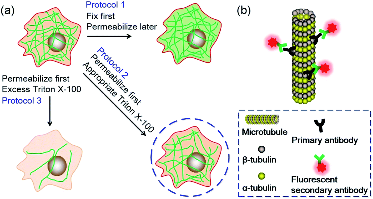 | ||
| Fig. 1 (a) Schematic illustration of the three different fluorescent immunolabeling protocols. The green lines represent microtubules. (b) Graphical illustration of the immunolabeling strategy. Images are not to scale. | ||
Results and discussion
CLSM imaging
The immunolabeling principle of microtubules is illustrated in Fig. 1b. β-Tubulin is used as the antigen, which can be recognized by the primary antibody (mouse anti-β-tubulin monoclonal antibody). The primary antibody is subsequently recognized by secondary antibodies. Two types of secondary antibodies are used. The first one is Alexa Fluor 647 labeled goat anti-mouse IgG polyclonal antibody (denoted as secondary antibody 1), the second one is quantum dots (QDs) labeled donkey anti-mouse IgG polyclonal antibody (denoted as secondary antibody 2). Fluorescence spectra of the two secondary antibodies are shown in Fig. S1 in the ESI.† Secondary antibody 1 is tagged with organic dyes and secondary antibody 2 is tagged with quantum dots. The main difference between these two kinds of antibodies is the size of the fluorophores. The diameter of QDs (e.g. 8–10 nm) is much larger than the size of the dye molecules (e.g. 1–2 nm). Testing antibodies with different sizes can better evaluate the cell membrane permeabilization results of TX100 and facilitate comprehensive investigations of the labeling results of different immunofluorescent labeling protocols.CLSM imaging results of HeLa cells labeled with secondary antibody 1 via different protocols are presented in Fig. 2. The detailed procedures of each protocol are presented in the Experimental section. Fig. 2a is a representative image of cells prepared using Protocol 1 (i.e. the ordinary fix first strategy). As can be seen, the microtubules are well preserved and stained. Such a standardized and widely used labeling strategy (i.e. Protocol 1) can well hold the natural status of microtubules right before the fixation of the cells. For cells prepared using Protocol 3, that is permeabilization first with 0.2% TX100, only a few microtubular fragments are left (Fig. 2b). The reason is that in Protocol 3, a relatively high concentration of TX100 (0.2%) is used. TX100 at such dosage can instantly destroy the integrity of microtubules by dissolving tubulins (since tubulins are TX100 soluble).16 While for cells labeled using Protocol 2, that is permeabilization first with 0.02% TX100, enormous microtubules are retained (Fig. 2c) and successfully labeled. However, the overall morphology of the microtubules in Fig. 2c (Protocol 2) is quite different from that shown in Fig. 2a (Protocol 1). Previous literature has reported that living HeLa cells become permeabilized with 0.17 mM (i.e. 0.011%) TX100 present.13 Since 0.02% TX100 is used in Protocol 2, it is reasonable that the microtubular morphology is different from Protocol 1, because some microtubules might be dissolved by TX100. We also tried TX100 with lower concentrations with 2 min permeabilization in Protocol 2, hoping to reduce the influence of microtubular morphology. As shown in Fig. S2 and S3 in the ESI,† not all the cells are labeled, indicating that permeabilization with less TX100 is insufficient. Besides, if we extend the permeabilization time (e.g. 3–4 min), most cells will detach from the culture dish even when TX100 with quite low concentrations is used (0.002% and 0.008%). Considering all the above, we concluded that permeabilizing with 0.02% TX100 for 1 min is optimal for Protocol 2. Fig. 2g and h are the reconstructed three-dimensional (3D) CLSM images of HeLa cells prepared using Protocol 1 and Protocol 2, which better proved that Protocol 2 can indeed preserve most microtubules (see the cross-sectional views).
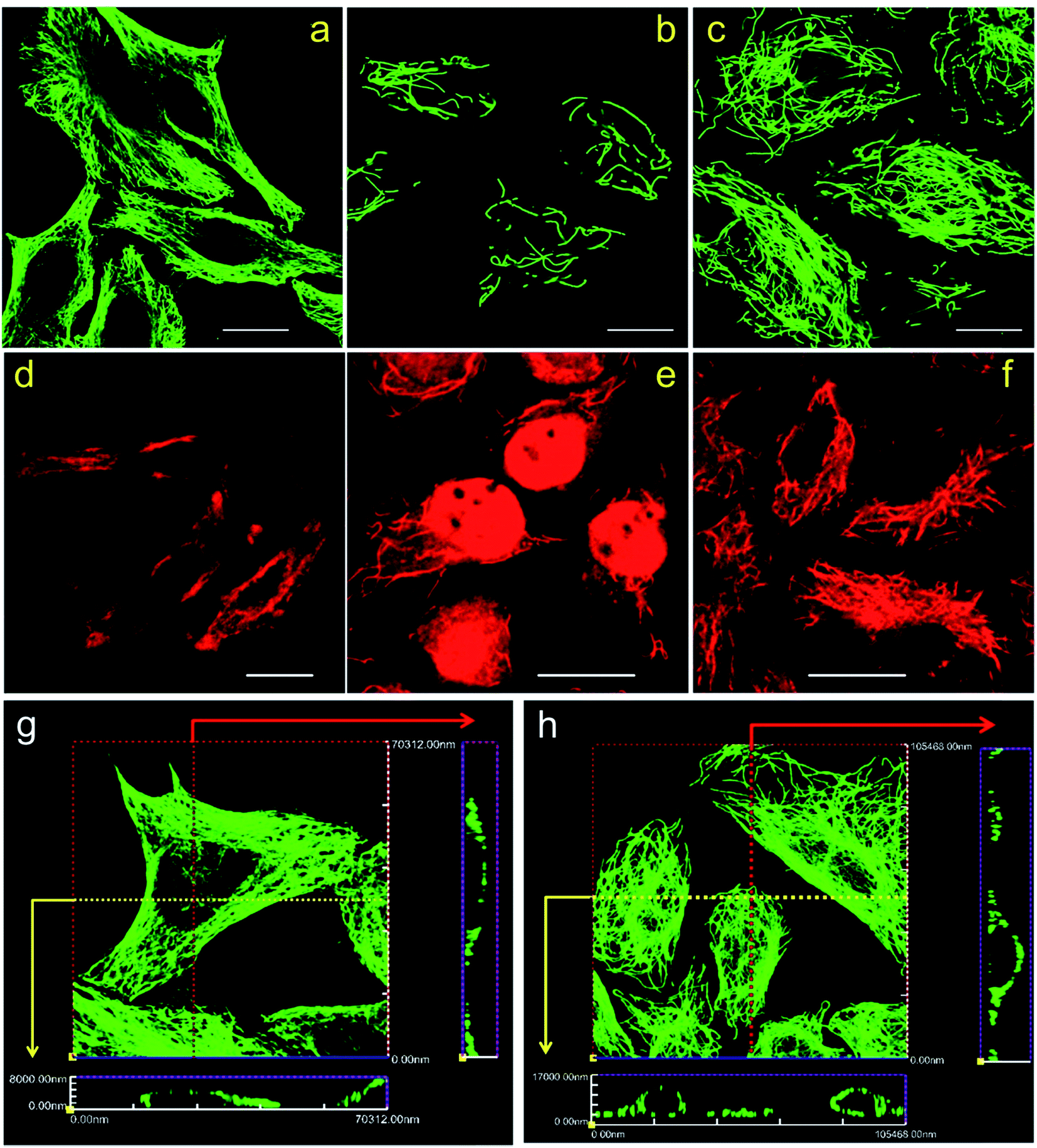 | ||
| Fig. 2 CLSM images of HeLa cells labeled using different protocols. (a and d) Protocol 1; (b and e) Protocol 3; (c and f) Protocol 2. (a–c) Secondary antibody 1 was used; (d–f) secondary antibody 2 was used. Scale bars: 20 μm. (g and h) Reconstructed three-dimensional CLSM images of HeLa cells prepared with Protocol 1 (g) and Protocol 2 (h). Secondary antibody 1 was used. The red and yellow arrows indicate the cross sectional views. Images are reconstructed from Z-stack CLSM slices with a step size of 1 μm. | ||
Fig. 2d–f are CLSM images of HeLa cells labeled with secondary antibody 2 using different protocols. For HeLa cells labeled using Protocol 1, high backgrounds are observed and the microtubular structures are hard to distinguish, indicating a low labeling specificity (Fig. 2d). For HeLa cells treated with Protocol 3 shown in Fig. 2e, similar to those shown in Fig. 2b, the microtubules are destroyed with only a small fraction left. Besides, secondary antibody 2 tends to adsorb on the remaining cell nucleus, which is a common phenomenon when adding quantum dot probes into fixed cells. While for HeLa cells labeled using Protocol 2 as presented in Fig. 2f, microtubules are successfully stained with a better specificity as compared with cells labeled via Protocol 1. When comparing Fig. 2f and d with 2c and a, it can be seen that the improved performance of Protocol 2 are more remarkable when secondary antibody 2 is used, because Fig. 2d exhibits a quite low specificity while Fig. 2f reveals a much better specificity. Possible reason might be that compared with secondary antibody 1, secondary antibody 2 is more likely to adsorb to non-specific binding sites. The immunolabeling specificity of QDs labeled antibodies (both customized and commercialized ones) is not as good as that of dyes labeled antibodies, we have observed such a phenomenon in our daily experiments. By searching the literature, we can also found that the labeling results of QDs are often poorer than dyes.11,17,18 So the high background of cells labeled with QDs might originate from the relatively poorer specificity of antibodies attached with QDs as compared with antibodies attached with dyes. Possible cause of the poorer immuno-specificity might be that the size of QDs (e.g. 8–10 nm) is much larger than that of the dye molecules (e.g. 1–2 nm). It is possible that such a large size of QDs might influence the immuno-specificity of the secondary antibody. However, by using the presented Protocol 2, the specificity of QDs labeled antibodies can be greatly improved as shown in Fig. 2f. Z-stack CLSM images of the cells shown in Fig. 2d–f are provided in the ESI as Fig. S4–S6,† respectively, which more vividly reveal the improved labeling efficiency of Protocol 2.
Worth mentioning is that in Protocol 1, we tried different TX100 concentrations (0.02%, 0.2% and 2%) and various permeabilization times (10 min, 15 min and 20 min) in the experiments, which all produced similar results. However, in Protocol 2, permeabilization only lasts for 1 min (see the Experimental section for more detail). Longer permeabilization time would cause the cells to detach from the dishes. Although permeabilizing cells first with TX100 can improve the labeling specificity, excess amount of TX100 will completely destroy the microtubular structure (Protocol 3). Consequently, TX100 here acts as a double-edged sword and requires careful control of its dosage and incubation time.
Next, to find out the applicability of Protocol 2 when labeling other types of cells, we performed immunofluorescent labeling of microtubules using MRC-5 cells and SKBR3 cells. Different protocols and different secondary antibodies are also tested, the results are presented in Fig. 3. Similarly, both MRC-5 and SKBR3 cells are severely damaged in Protocol 3, leaving only a few fragmental microtubules (see Fig. 3b, e, h and k). High backgrounds and low labeling specificity are observed in cells prepared via Protocol 1 (see Fig. 3a, d, g and j). While for cells treated with Protocol 2, excellent labeling specificity is achieved (see Fig. 3c, f, i and l). Z-stack CLSM images of the cells shown in Fig. 3 are presented in the ESI as Fig. S7–S18,† which more convincingly prove the better immunofluorescent labeling results of Protocol 2. Previously literature has mentioned that treating cells first with TX100 can improve labeling specificity of tissues.19 Here, by using different cell lines, we more thoroughly investigated the role of TX100 in immunofluorescent labeling of microtubules.
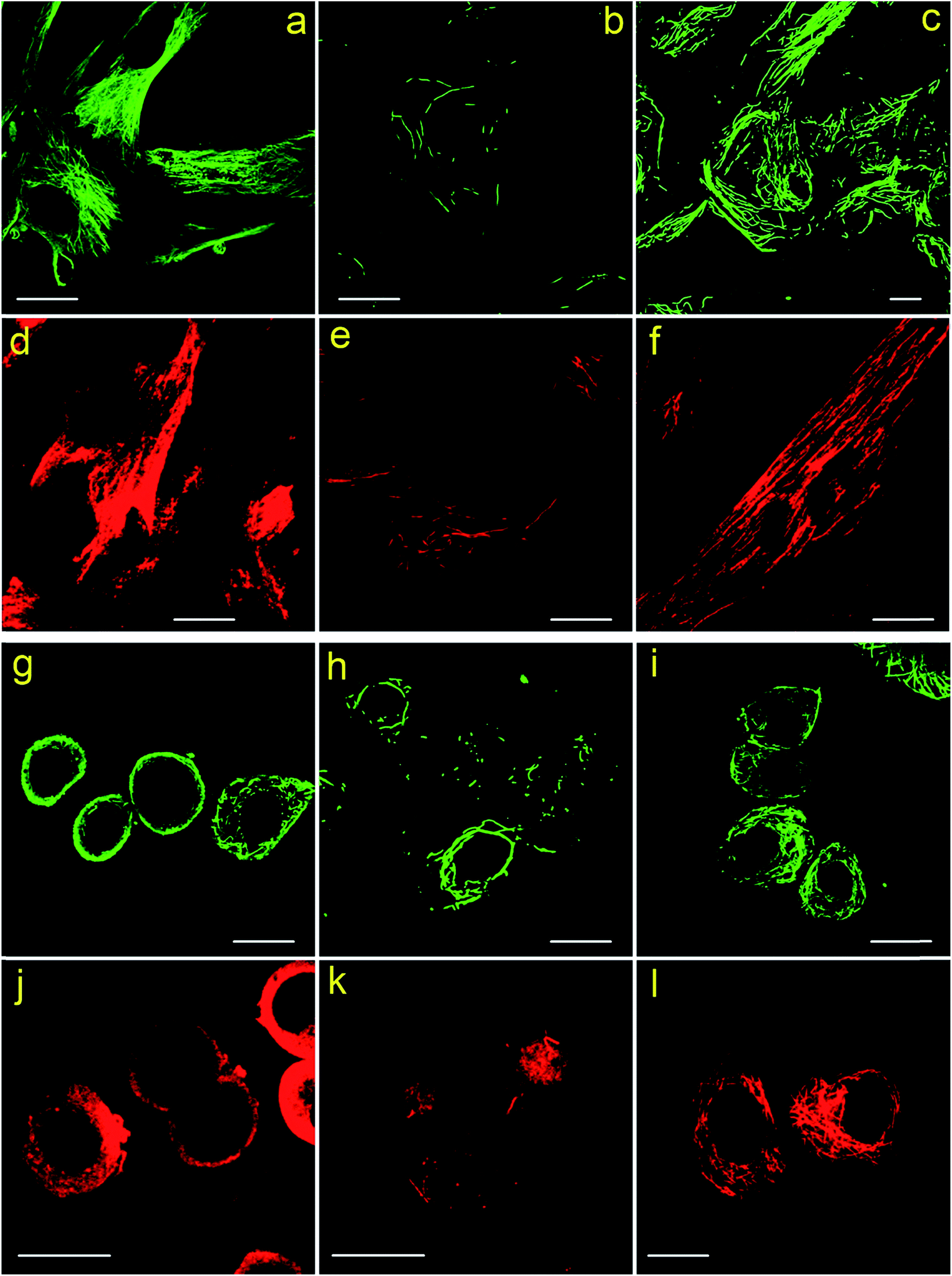 | ||
| Fig. 3 (a–f) CLSM images of MRC-5 cells labeled using different protocols. (a and d) Protocol 1; (b and e) Protocol 3; (c and f) Protocol 2. (a–c) Secondary antibody 1 was used; (d–f) secondary antibody 2 was used. Scale bars: 20 μm. (g–l) CLSM images of SKBR3 cells labeled using different protocols. (g and j) Protocol 1; (h and k) Protocol 3; (i and l) Protocol 2. (g–i) Secondary antibody 1 was used; (j–l) secondary antibody 2 was used. Scale bars: 20 μm. | ||
To explore the reason why Protocol 2 can support an improved labeling specificity, we conducted coomassie brilliant blue (CBB) and PKH26 staining of cells. CBB can stain the proteins remained in the cells and PKH26 can label the cell membrane. Since we are trying to study the intrinsic difference among cells prepared by various protocols, cells are only fixed and permeabilized (without the addition of blocking serums and antibodies). Detailed staining procedures are presented in the Experimental section. The results are shown in Fig. 4. Fig. 4a–c are cells labeled with CBB, darker image means more CBB molecules are bind to the cells (i.e. more proteins are retained in these cells). So it is obvious that the amount of remained proteins in cells treated with different protocols is Protocol 1 > Protocol 2 > Protocol 3. Fig. 4d–f are cells labeled with PKH26, brighter image means more PKH26 molecules are labeled to the cells (i.e. more lipid membranes are left in these cells). Clearly, the amount of remained lipid membranes in cells treated via different protocols is Protocol 1 < Protocol 2 ≈ Protocol 3. Besides, we also stained the membrane of cells which are only fixed with PFA without membrane permeabilization by TX100. The result is presented in Fig. S19 in the ESI,† which is similar to Fig. 4e and f. This indicates that the membranes of cells prepared by Protocol 2 and Protocol 3 are relatively intact. Such a result of lipid membrane contents is rational considering the fact that cells are incubated with TX100 for 20 min in Protocol 1 while only for 1 min in Protocol 2 and Protocol 3. Considering all the above results in Fig. 4, we came to the following conclusion. For cells prepared via Protocol 1, the cell membranes are dissolved to a large extent yet the cellular proteins are well preserved. For cells prepared via Protocol 2, the cell membranes are well preserved and quite a few cellular proteins are also retained. For cells prepared via Protocol 3, the cell membranes are well preserved yet many proteins are dissolved. In Protocol 2 and Protocol 3, although living cells are only incubated with TX100 for 1 min, it is still sufficient for TX100 to extract TX100 soluble proteins. Besides, membrane punching is also enough with such a short permeabilization time since primary and secondary antibodies can penetrate through the cell membrane in Protocol 2 and Protocol 3 (otherwise microtubules will not be stained in Protocol 2 and Protocol 3).
 | ||
| Fig. 4 CBB stained cells (a–c) and PKH26 labeled cells (d–f). (a and d) Cells prepared via Protocol 1. (b and e) Cells prepared via Protocol 2. (c and f) Cells prepared via Protocol 3. The scale bars in (a–c) are 20 μm and those in (d–f) are 50 μm. | ||
Hence, detailed mechanism of the improved labeling specificity observed in Protocol 2 can be explained as follows. On one hand, TX100 acts both as the membrane pemeabilization and protein extraction agents.20 As a nonionic detergent, TX100 can break the binding between lipid–protein yet has a relatively weak influence on protein–protein binding. On the other hand, proteins in fixed cells are covalently cross-linked as a network by the fixative (i.e. PFA), keeping the steric configuration of the proteins unchanged as well as maintaining the antigenicity of the proteins. Considering these two facts, the difference in labeling specificity of cells treated by different protocols becomes reasonable. For cells fixed first (i.e. Protocol 1), proteins (especially those in the cytoplasm) are cross-linked and become insoluble toward TX100. Consequently, TX100 can only disrupt the lipid membrane and extract membrane proteins (see Fig. 4a and d), leaving behind most of the cytoplasmic fixed proteins (including microtubules). The remaining cross-linked proteins can act as non-specific binding sites during immunofluorescent labeling, resulting in a relatively high background and a low specificity. Contrarily, for cells treated with TX100 first (i.e. Protocol 2), proteins are not fixed. Upon adding into the living cells, TX100 can instantly punch into the cytoplasm and dissolve as much soluble proteins as possible. Microtubules are formed by polymerization of tubulin dimers, which represents relatively strong protein–protein interactions. As a result, microtubules are dissolved relatively slow by TX100. If properly controlled, most of the microtubules can be preserved. Since TX100 soluble proteins have already been extracted by TX100 (see Fig. 4b), less non-specific binding sites are left in these cells. Hence, a quite high labeling specificity of microtubules is achieved. However, if extensive TX100 is added to living cells (i.e. Protocol 3), similar to cell lysis, plenty of proteins are dissolved, leaving only a small fraction of broken microtubules, the cell nucleus and some TX100 insoluble proteins (e.g. F-actin filaments) (see Fig. 4c).21,22 Thus, the mechanism under the improved labeling specificity of Protocol 2 is uncovered.
If comparing the labeling results of HeLa, MRC-5 and SKBR3 cells treated via Protocol 2, one can find that the overall integrity of retained microtubules is SKBR3 > HeLa > MRC-5 (see Fig. 2 and 3 and the Z-stack images in Fig. S9 and S15†). One possible explanation is that the tolerance of microtubules of living cells toward 0.02% TX100 is SKBR3 > HeLa > MRC-5, hence, SKBR3 cells can still maintain a fine microtubular morphology. However, even for SKBR3 cells, the amount of TX100 still requires careful control, otherwise microtubules will also be broken (Fig. 3h and k).
AFM imaging
To further study the morphological differences between cells labeled using different protocols, we also performed AFM measurements of immunofluorescent labeled cells, using HeLa cells as a representative. A commercialized Bruker Bioscope Resolve AFM system is used, which is mounted on an inverted epi-fluorescence microscope. This system allows simultaneous collection of AFM and fluorescence images of the same sample region. At present, the field of view (FOV) of the epi-fluorescence microscope is only approximately 50 μm due to its optical alignments. Besides, fluorescence images and AFM images are collected using two separate softwares (Micro-Manager 1.4 and Nanoscope 9.2, respectively) due to incompatibility between the AFM software (Nanoscope 9.2) and the CCD (Photometrics, CoolSNAP MYO) of the epi-fluorescence microscope. As a result, FOVs of the AFM and fluorescence microscope are not overlapped precisely. In spite of these inconvenience, the AFM system can still be used to perform a rough colocalization of the AFM and fluorescence images. Representative results are shown in Fig. 5, where AFM, fluorescence and merged AFM-fluorescence images are all presented. The upper panel is HeLa cells labeled using Protocol 1, the middle panel is HeLa cells labeled using Protocol 2 and the lower panel is HeLa cells treated with Protocol 3. The epi-fluorescence images in Fig. 5b1–b3 are similar to the CLSM images presented in Fig. 2a–c. The AFM images also reveal that soundness of the morphology of cells treated with different protocols is Protocol 1 > Protocol 2 > Protocol 3 (Fig. 5a1–a3), which corresponds well with the fluorescence images. The 3D AFM images shown in Fig. 6a1–a3 more clearly support such a conclusion. Besides, the heights of the cells treated by different protocols are Protocol 1 > Protocol 2 > Protocol 3 (Fig. 6b1–b3). This is reasonable since the amount of remained proteins in these cells also follows such an order (see Fig. 4). From the AFM-fluorescence colocalization results, we affirmed that Protocol 1 can well keep the microtubular structure because cells are killed and fixed first. Protocol 2 permeabilize live cells first with TX100, hence, the microtubules are partially solubilized by TX100. Protocol 3 utilized an excess amount of TX100, which instantly dissolves soluble proteins (including tubulins), remaining only a few microtubule segments. So the difference between the morphology of cells treated with different protocols can be summarized as follows. For cells treated with Protocol 1, proteins are cross-linked and become insoluble toward TX100. Consequently, all these proteins will be retained during the whole labeling procedure and thus the morphology of cells treated with Protocol 1 is well preserved (Fig. 6a). For cells treated with Protocol 2, TX100 can dissolve as much soluble proteins as possible. Besides, microtubules are dissolved relatively slow by TX100. So most of the microtubules will remain during the labeling procedures and the cell morphology is partially damaged due to the extraction of TX100 soluble proteins (Fig. 6b). For cells treated with Protocol 3, plenty of proteins are dissolved due to the excess amount of TX100, leaving only a small fraction of broken microtubules, thus the integrity of cell morphology is greatly damaged (Fig. 6c). The AFM-fluorescence colocalization results more directly demonstrate the subtle yet important role of TX100 in microtubular labeling.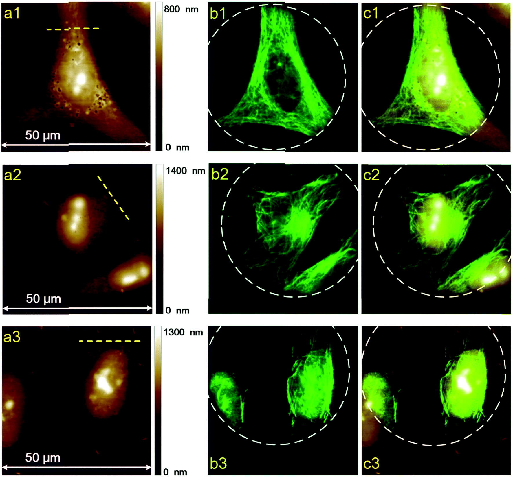 | ||
| Fig. 5 Two-dimensional AFM and fluorescence images of HeLa cells labeled using different protocols. Secondary antibody 1 is used. The color-coded scale bars on the right side of the AFM images represent heights. (a1–c1) Protocol 1, (a2–c2) Protocol 2, (a3–c3) Protocol 3. (a) AFM images, (b) fluorescence images, (c) merged AFM and fluorescence images. The white dashed circles indicate the FOV of the epi-fluorescence microscope. | ||
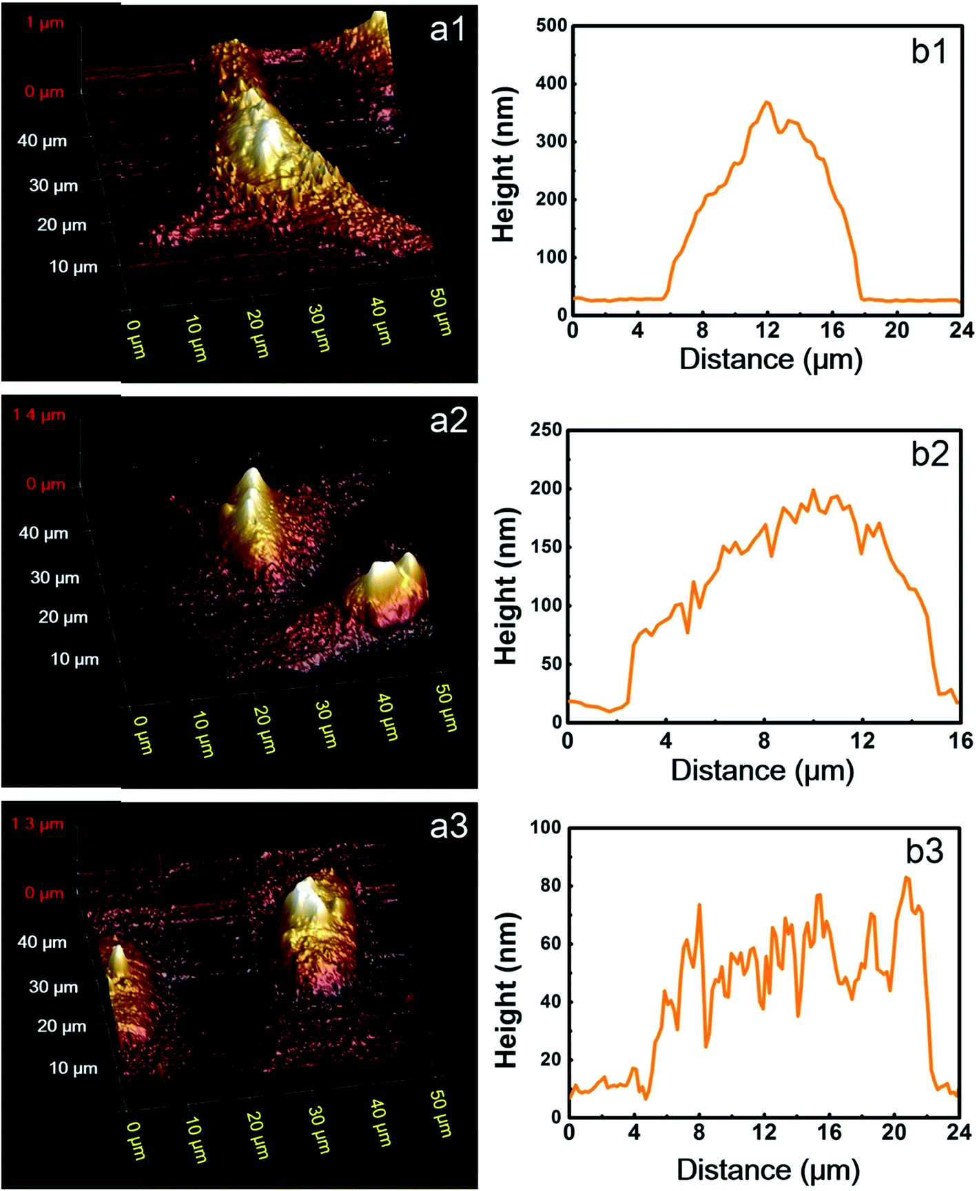 | ||
| Fig. 6 (a) 3D AFM images of the identical HeLa cells shown in Fig. 3. (b) The height distributions along the yellow dashed lines shown in Fig. 5a. (a1 and b1) HeLa cells labeled using Protocol 1, (a2 and b2) HeLa cells labeled using Protocol 2, (a3 and b3) HeLa cells labeled using Protocol 3. | ||
SMLM imaging
Finally, we try to find out if Protocol 2 is also suitable for preparing optical super resolution imaging samples since microtubule is a quite popular object in super resolution imaging. SMLM is one of the optical super resolution imaging techniques which can break the diffraction limits.23,24 SMLM utilizes repetitive imaging and localization cycles to reconstruct super-resolved images.25–29 Secondary antibody 1 in our experiments is tagged with Alexa Fluor 647, which has been proven to be an excellent fluorophore for SMLM applications.30 Hence, we conducted SMLM imaging of microtubules using HeLa cells as an example. HeLa cells were labeled using different protocols and imaged with a Zeiss Elyra P.1 system. The results are shown in Fig. 7, where both wide field and SMLM images are presented. The first thing for sure is that SMLM images all exhibit an improved spatial resolution as compared with wide field images no matter which one of the protocol is used. Localization precisions of microtubules labeled via different protocols are similar as can be seen from Fig. 8a (around 20 nm). This is rational since localization precision is primarily determined by the fluorophore itself and the microscope system. Fig. 8c shows the intensity profiles obtained from wide field and SMLM images along the red dashed line region in Fig. 7a2. The yellow shadows indicate that microtubules indistinguishable in the wide field image can be well resolved in the SMLM image, confirming a much better spatial resolution of SMLM. After carefully checking the SMLM images (see the enlarged SMLM images in Fig. 7), one can find that high backgrounds are detected in microtubules labeled with Protocol 1 while negligible backgrounds are observed in samples prepared via Protocol 2 and Protocol 3 (Fig. 8b). The sparse bright spots observed in the background of the enlarged SMLM image of Protocol 1 must originate from non-specific binding sites. This means that the improved labeling specificity of Protocol 2 is more evident when samples are imaged using SMLM, which in turn more convincibly strengthens the explanation on why Protocol 2 produces higher labeling specificity (because less non-specific proteins are left in Protocol 2). More importantly, as can be seen from the dashed white circles in the enlarged SMLM images (as well as Fig. S20 in the ESI†), closely packed microtubules can be well resolved in Protocol 2 while poorly distinguishable in Protocol 1, indicating that the improved labeling specificity of Protocol 2 also can support a better spatial resolution. Possible reason of the poor spatial resolution of Protocol 1 can be explained as follows. The main cause is the enormous non-specific binding sites presented in cells treated by Protocol 1. First, antibodies will bind to these non-specific sites, resulting in a lower labeling density of microtubules. Second, Alexa Fluor 647 tagged on the non-specific sites will also fluoresce during SMLM, which is a huge interference toward those tagged on microtubules, resulting in less effective localization cycles and thus poor image qualities.31 We have tried antibodies with higher concentrations and longer SMLM image acquisition times, making sure that plenty of antibodies were present and the localization cycles were sufficient. However, this made no big difference to the final results. The above experimental observations proved that excellent labeling specificity matters much in SMLM imaging and Protocol 2 is a more superior choice as compared with Protocol 1 when performing SMLM experiments.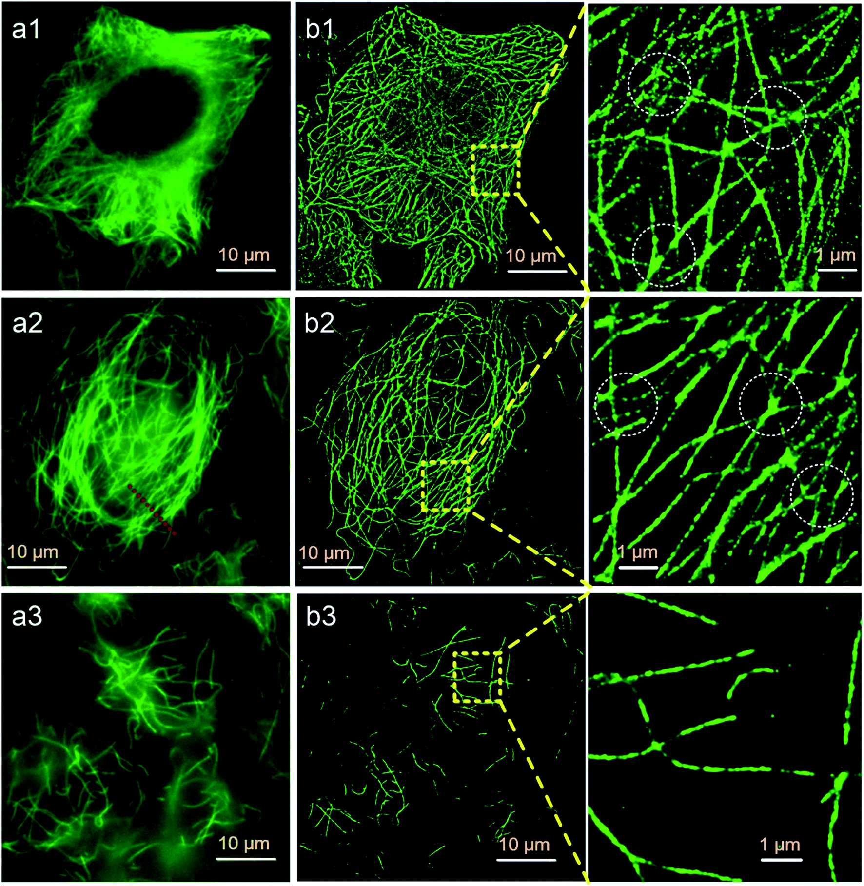 | ||
Fig. 7 SMLM imaging results of HeLa cells prepared using different labeling protocols. SMLM images are reconstructed from 20![[thin space (1/6-em)]](https://www.rsc.org/images/entities/char_2009.gif) 000 frames with an exposure time of 30 ms. (a1 and b1) Protocol 1, (a2 and b2) Protocol 2, (a3 and b3) Protocol 3. Left panel: wide field fluorescence images, middle panel: SMLM images, right panel: enlarged SMLM images of the regions as indicated by the yellow dashed boxes. 000 frames with an exposure time of 30 ms. (a1 and b1) Protocol 1, (a2 and b2) Protocol 2, (a3 and b3) Protocol 3. Left panel: wide field fluorescence images, middle panel: SMLM images, right panel: enlarged SMLM images of the regions as indicated by the yellow dashed boxes. | ||
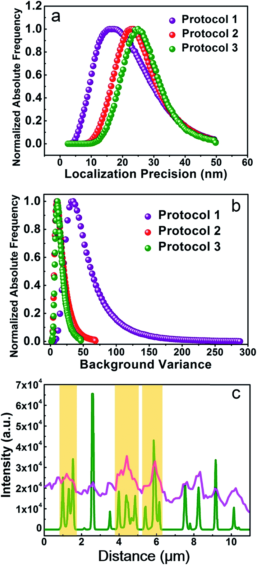 | ||
| Fig. 8 (a) Localization precisions, (b) background levels, (c) pink curve: intensity profile along the red dashed line in the wide field image shown in Fig. 7a2. Green curve: intensity profile along the same region in the SMLM image shown in Fig. 7b2. The data are analyzed using the Zeiss Zen 2012 software. | ||
Conclusions
A new immunofluorescent labeling strategy for microtubule is presented, in which living cells are permeabilized first with TX100 and then fixed with aldehydes. Such an innovative protocol (i.e. Protocol 2) is proven to hold high labeling specificity and low backgrounds as compared with the ordinary immunofluorescent labeling protocol (i.e. Protocol 1). TX100 in Protocol 2 acts like a double-edged sword. On one hand, TX100 can permeabilize membranes of living cells and extract non-specific proteins to improve the labeling specificity. On the other hand, it can also instantly damage microtubules. As a result, usage of TX100 requires elaborate control. The experimental results show that treating cells first with 0.02% TX100 for 1 min and then fixing cells with aldehydes is an optimal strategy (i.e. the Protocol 2). Besides, different cell lines exhibit various tolerance toward TX100. For example, microtubules of SKBR3 cells are perfectly reserved while those of MRC-5 cells are partially damaged to a relatively high extent when labeling via Protocol 2. Consequently, we suggest that whether to use Protocol 1 or Protocol 2 should be determined according to specific applications. For example, when studying the structural or dynamical characteristics of microtubules, Protocol 1 would be a better choice since it can well preserve the exact status of microtubules. While if one is trying to obtain a SMLM image with high quality or testing the performance of newly developed antibodies and fluorophores, Protocol 2 can be a fine choice since it will provide an excellent labeling specificity. It is hopeful that such an innovative Protocol 2 can be generalized to other cell lines although the dosage and permeabilization time of TX100 might require a little adjustments. In summary, the new protocol produces extraordinary microtubular labeling results yet it is quite simple, which demonstrates excellent potentials in microtubule-related studies.Experimental section
Materials
Sodium borohydride (NaBH4) and glutaraldehyde (GA) were purchased from Alfa Aesar. Mouse anti-β-tubulin monoclonal antibody (primary antibody), Alexa Fluor 647 labeled goat anti-mouse IgG polyclonal antibody (secondary antibody 1) and quantum dot labeled donkey anti-mouse IgG polyclonal antibody (secondary antibody 2) were purchased from ThermoFisher Scientific. PKH26 kit for cell membrane labeling was obtained from Sigma-Aldrich. TX100 was purchased from Aladdin®. Polyformaldehyde (PFA, 4% in PBS), coomassie brilliant blue (CBB) protein staining kit and PBS buffer were purchased from KeyGEN BioTECH. Normal goat serum (NGS) was purchased from BOSTER Biological Technology. Normal donkey serum (NDS) was purchased from Jackson ImmunoResearch. All the reagents were used as received. Deionized water (Millipore Milli-Q grade) with a resistivity of 18 MΩ cm−1 was used in all the experiments.Cell culture and immunofluorescent labeling
Protocol 1. First, the culture medium in the chamber slide was discarded and cells were washed gently with PBS for three times. Then, cells were fixed with fixation solution (4% PFA and 0.1% GA) for 20 min at room temperature. After discarding the fixation solution, cells were washed with PBS for three times (5 min each). Next, cells were treated with NaBH4 (1 mg mL−1 in PBS) for 7 min under gentle shaking to reduce autofluorescence. After washing cells again with PBS, permeabilization solution (0.2% TX100 in PBS) was added into the chamber and incubated for 20 min upon gentle shaking. Then, the permeabilization solution was discarded and blocking solution (NGS or NDS, 1% in PBS) was added into the cell chamber and incubated for 1 h under gentle shaking to block nonspecific adsorption sites. Whether to use NGS or NDS depends on the species of the secondary antibodies. For secondary antibody 1, the blocking solution should be NGS. For secondary antibody 2, the blocking solution should be NDS. When blocking was finished, primary antibody (1 μg mL−1 in PBS) was added into the cell chamber and incubated at 4 °C for 12 h. Then, the cells were washed with PBS for three times (5 min each) to remove excess primary antibodies. After that, secondary antibody (2 μg mL−1 in PBS) was added into the cell chamber and incubated at room temperature for 1 h upon gentle shaking. Excess secondary antibodies were removed by washing with PBS for three times (5 min each). Finally, fixation solution was added into the chamber and incubated for 2 min. After replacing the fixation solution with PBS, the cells were ready for fluorescence imaging.
Protocol 2. First, the culture medium in the chamber slide was discarded and cells were washed gently with PBS for three times. Then, permeabilization solution (0.02% TX100 in PBS) was added into the chamber and incubated for 1 min upon gentle shaking. After discarding the permeabilization solution, cells were washed with PBS once, followed by the addition of fixation solution (4% PFA and 0.1% GA). The fixation reaction continued for 20 min and cells were subsequently washed with PBS for three times (5 min each). Next, cells were treated with NaBH4 (1 mg mL−1 in PBS) for 7 min under gentle shaking. When the reducing procedure finished, cells were washed with PBS again and blocking solution (NGS or NDS, 1% in PBS) was added. One hour later, the blocking solution was discarded and primary antibody was added. The following procedures were the same to Protocol 1.
Protocol 3. The experimental procedures of Protocol 3 are almost identical to those of Protocol 2, except that 0.2% TX100 was used as the permeabilization solution.
During CBB staining, cells are prepared as follows. For cells treated with Protocol 1, they are fixed first and then permeabilized. After reducing with NaBH4, CBB staining solution was added. While for cells treated with Protocol 2 and Protocol 3, they are permeabilized first and then fixed. After reducing with NaBH4, CBB staining solution was added. Cells were incubated with CBB for 30 min. Then excess CBB was removed and the cells were washed with PBS for 3 times (5 min each). Finally, the cells were mounted onto the CLSM and bright field (i.e. transmittance) images were collected.
For cell membrane labeling, cells treated with different protocols were staining using PKH26. For cells treated with Protocol 1, they are fixed first and then permeabilized. After that, PKH26 was added into these cells. For cells treated with Protocol 2 and Protocol 3, they are permeabilized first and then fixed, followed by the addition of PKH26. Membrane staining continued for 5 min. Then, NGS was added to stop the staining reaction. Finally, cells were washed with PBS and mounted onto the CLSM for fluorescence imaging. The excitation wavelength of PKH26 was 543 nm and photons with wavelengths of 555–605 nm were collected.
For AFM imaging, cells were seeded into 35 mm culture dish (glass bottom) and incubated for 24 h. Immunofluorescent labeling procedures were the same to cells seeded in chamber slides. Then the fluorescence labeled cells were gently washed with deionized water for three times. After discarding the deionized water, cells in the culture dish were dried slowly under ambient air. The dried cells were subjected to AFM imaging.
In SMLM experiments, secondary antibody 1 labeled cells were immersed in imaging buffer prepared according to previous published literature.30 405 nm laser was used as the activation laser and 642 nm laser was used as the illumination laser. A 655 nm long pass filter was utilized to screen the emission lights.
Instruments
CLSM imaging was performed with an Olympus FV1000 confocal microscope. SMLM imaging was conducted using a Zeiss Elyra P.1 microscope. SMLM images was recorded using a 100× oil immersion objective and an Andor EM-CCD camera (iXon DU897). Imaging data were analyzed using the Zeiss Zen 2012 software. AFM image was obtained using a Bruker Bioscope Resolve AFM mounted on an inverted epi-fluorescence microscope (Olympus IX73). The AFM system allows colocalization of the AFM and fluorescence images of the same region. AFM images were acquired using a silicon nitride cantilever (SCANASYST-AIR, Bruker, k: 0.4 N m−1) in the ScanAsyst in Air mode. Fluorescence images of the same region were collected using a 60× oil immersion objective with a halogen lamp as the excitation.Conflicts of interest
The authors declare no competing financial interests.Acknowledgements
This work was supported by the National Key Basic Research Program of China (2015CB352002), the Natural Science Foundation of China (NSFC) (61535003, 61675042, 61505027), the Natural Science Foundation of Jiangsu Province (BK20150623), the Excellent Youth Foundation of Jiangsu Province (BK20140023), and the Fundamental Research Funds for the Central Universities (2242016KD007, 2242017K41010).References
- X. Y. Wu, H. J. Liu, J. Q. Liu, K. N. Haley, J. A. Treadway, J. P. Larson, N. F. Ge, F. Peale and M. P. Bruchez, Nat. Biotechnol., 2003, 21, 41–46 CrossRef CAS PubMed.
- T. Suzuki, T. Matsuzaki, H. Hagiwara, T. Aoki and K. Takata, Acta Histochem. Cytochem., 2007, 40, 131–137 CrossRef CAS PubMed.
- D. Yang, Q. Chen, W. Wang and S. Xu, Luminescence, 2008, 23, 169–174 CrossRef CAS PubMed.
- E. H. Beutner and R. E. Jordon, Proc. Soc. Exp. Biol. Med., 1964, 117, 505–510 CrossRef CAS PubMed.
- M. A. Jordan and L. Wilson, Nat. Rev. Cancer, 2004, 4, 253–265 CrossRef CAS PubMed.
- F. Z. Li, G. Ambrosini, E. Y. Chu, J. Plescia, S. Tognin, P. C. Marchisio and D. C. Altieri, Nature, 1998, 396, 580–584 CrossRef CAS PubMed.
- A. Desai and T. J. Mitchison, Annu. Rev. Cell Dev. Biol., 1997, 13, 83–117 CrossRef CAS PubMed.
- J. V. Kilmartin, B. Wright and C. Milstein, J. Cell Biol., 1982, 93, 576–582 CrossRef CAS PubMed.
- F. L. Tomson, V. K. Viswanathan, K. J. Kanack, R. P. Kanteti, K. V. Straub, M. Menet, J. B. Kaper and G. Hecht, Mol. Microbiol., 2005, 56, 447–464 CrossRef CAS PubMed.
- M. Mikhaylova, B. M. C. Cloin, K. Finan, R. van den Berg, J. Teeuw, M. M. Kijanka, M. Sokolowski, E. A. Katrukha, M. Maidorn, F. Opazo, S. Moutel, M. Vantard, F. Perez, P. M. P. V. B. E. Henegouwen, C. C. Hoogenraad, H. Ewers and L. C. Kapitein, Nat. Commun., 2015, 6, 7933 CrossRef CAS PubMed.
- X. Chen, R. Li, Z. Liu, K. Sun, Z. Sun, D. Chen, G. Xu, P. Xi, C. Wu and Y. Sun, Adv. Mater., 2017, 29, 1604850 CrossRef PubMed.
- D. Kim, T. J. Deerinck, Y. M. Sigal, H. P. Babcock, M. H. Ellisman and X. Zhuang, PLoS One, 2015, 10, e0124581 Search PubMed.
- D. Koley and A. J. Bard, Proc. Natl. Acad. Sci. U. S. A., 2010, 107, 16783–16787 CrossRef CAS PubMed.
- A. L. van de Ven, K. Adler-Storthz and R. Richards-Kortum, J. Biomed. Opt., 2009, 14, 021012 CrossRef PubMed.
- V. R. Dayeh, S. L. Chow, K. Schirmer, D. H. Lynn and N. C. Bols, Ecotoxicol. Environ. Saf., 2004, 57, 375–382 CrossRef CAS PubMed.
- A. D. Bershadsky, V. I. Gelfand, T. M. Svitkina and I. S. Tint, Cell Biol. Int. Rep., 1978, 2, 425–432 CrossRef CAS PubMed.
- Z. Zeng, X. Chen, H. Wang, N. Huang, C. Shan, H. Zhang, J. Teng and P. Xi, Sci. Rep., 2015, 5, 8359 CrossRef CAS PubMed.
- X. Yang, K. Zhanghao, H. Wang, Y. Liu, F. Wang, X. Zhang, K. Shi, J. Gao, D. Jin and P. Xi, ACS Photonics, 2016, 3, 1611–1618 CrossRef CAS.
- S. S. Ghrebi, G. R. Owen and D. M. Brunette, Microsc. Res. Tech., 2007, 70, 555–562 CrossRef CAS PubMed.
- U. Kragh-Hansen, M. le Maire and J. V. Moller, Biophys. J., 1998, 75, 2932–2946 CrossRef CAS PubMed.
- N. Golenhofen, R. B. Doctor, R. Bacallao and L. J. Mandel, Kidney Int., 1995, 48, 1837–1845 CrossRef CAS PubMed.
- M. Bustamante, F. Roger, M. L. Bochaton-Piallat, G. Gabbiani, P. Y. Martin and E. Feraille, Am. J. Physiol. Ren. Physiol., 2003, 285, F336–F347 CrossRef CAS PubMed.
- B. Huang, H. Babcock and X. Zhuang, Cell, 2010, 143, 1047–1058 CrossRef CAS PubMed.
- L. Schermelleh, R. Heintzmann and H. Leonhardt, J. Cell Biol., 2010, 190, 165–175 CrossRef CAS PubMed.
- B. Huang, W. Wang, M. Bates and X. Zhuang, Science, 2008, 319, 810–813 CrossRef CAS PubMed.
- E. Betzig, G. H. Patterson, R. Sougrat, O. W. Lindwasser, S. Olenych, J. S. Bonifacino, M. W. Davidson, J. Lippincott-Schwartz and H. F. Hess, Science, 2006, 313, 1642–1645 CrossRef CAS PubMed.
- M. J. Rust, M. Bates and X. Zhuang, Nat. Methods, 2006, 3, 793–795 CrossRef CAS PubMed.
- C. Chen, S. Zong, Z. Wang, J. Lu, D. Zhu, Y. Zhang and Y. Cui, ACS Appl. Mater. Interfaces, 2016, 8, 25825–25833 CAS.
- S. Zong, X. Jiang, Z. Wang, C. Chen, J. Lu, L. Wang, D. Zhu and Y. Cui, Nanoscale, 2016, 8, 19110–19119 RSC.
- G. T. Dempsey, J. C. Vaughan, K. H. Chen, M. Bates and X. Zhuang, Nat. Methods, 2011, 8, 1027–1036 CrossRef CAS PubMed.
- M. Bates, S. A. Jones and X. Zhuang, Cold Spring Harb. Protoc., 2013, 2013, 498–520 Search PubMed.
Footnote |
| † Electronic supplementary information (ESI) available. See DOI: 10.1039/c7ra06949a |
| This journal is © The Royal Society of Chemistry 2017 |