 Open Access Article
Creative Commons Attribution 3.0 Unported Licence
Highly uniform hierarchical Zn2SnO4 microspheres for the construction of high performance dye-sensitized solar cells†
Xin Wangab,
Yu-Fen Wang*ab,
Qiu-Ping Luoc,
Jian-Hua Renab,
De-Jun Liab and
Xi-Fei Li *ab
*ab
aEnergy & Materials Engineering Center, College of Physics and Materials Science, Tianjin Normal University, Tianjin 300387, China. E-mail: xfli@mail.tjnu.edu.cn; yfwang@mail.tjnu.edu.cn
bTianjin International Joint Research Center of Surface Technology for Energy Storage Materials, Tianjin 300387, China
cLaboratory of Optical Information Technology, School of Science, Wuhan Institute of Technology, Wuhan 430205, China
First published on 8th September 2017
Abstract
3D hierarchical Zn2SnO4 microspheres show great potential as alternative photoanodes for dye-sensitized solar cells (DSSCs). Herein, hierarchical Zn2SnO4 microspheres with different sizes are fabricated via a one-step hydrothermal method, and a plausible formation process for Zn2SnO4 microspheres is proposed. The DSSCS devices based on 1.20 μm Zn2SnO4 microspheres show the best power conversion efficiency (PCE) of 4.00%. Further, TiCl4 treatment of a Zn2SnO4 microsphere photoanode results in an improved PCE up to 4.72%.
1. Introduction
Since the pioneering report of dye-sensitized solar cells (DSSCs) by M. Grätzel in 1991, tremendous progress has been witnessed in this field over the past decades.1,2 So far, the highest power conversion efficiencies (PCEs) of more than 14% have been demonstrated.3 The photoanodes, composed of wide-band-gap semiconducting metal oxide films (such as TiO2, ZnO, SnO2 and Zn2SnO4) with a large internal surface area, play a key role in affecting the photovoltaic performance of DSSCs.4–11 Ternary oxide semiconductors, such as Zn2SnO4, have attracted worldwide attention due to their promising optical and electrical properties. Firstly, Zn2SnO4 possesses a wide band gap of 3.8 eV (TiO2: 3.2 eV), whose conduction band position is similar to that of TiO2 and ZnO. However, for these two metal oxides, TiO2 and ZnO, the UV region of the solar spectrum suffers from photobleaching when applied as photoanodes in DSSCs;12 secondly, Zn2SnO4 with a higher electron mobility of 10–15 cm2 V−1 s−1 than TiO2 (10–5 cm2 V−1 s−1) implies more efficient electron transport characteristic in DSSCs.13,14 Thirdly, unlike ZnO, for which the Zn-dye + complex can decrease the photocurrent (Jsc) and photovoltage (Voc), Zn2SnO4 shows better chemical stability in acid/based solution.15 Last but not least, Zn2SnO4 possesses tunable work function and electric resistivity. It is well-known that the hierarchical structured materials have several advantages while are applied in DSSCs, for instance, the large specific surface area could induce efficient dye adsorption, outstanding light-scattering ability could induce efficient light harvesting, and well-interconnected structures could induce boosted electron transport and suppressed electron recombination.16–18 But, fabrication of Zn2SnO4 microspheres with uniform morphological features pose the greatest challenge in their preparation because such ternary oxide needs high temperature (>200 °C) to crystallize and regulate the Zn and Sn ions during synthetic process.In this work, we demonstrate a facile one-step hydrothermal process to fabricate 3D hierarchically Zn2SnO4 microspheres consisting of nanoplates, which could offer not only larger surface areas but also would result in a better light-scattering ability as well as electricity-generation properties. In addition, TiO2-coated hierarchical Zn2SnO4 microspheres (∼1.2 μm in diameter) are used as photoanode materials for improved PCE in DSSCs. The highest PCE in this work up to 4.72% has been achieved.
2. Experimental
2.1 Synthesis
Hierarchical Zn2SnO4 microspheres are synthesized via a one-step hydrothermal process. Typically, 1.402 g SnCl4·5H2O (A.R.), 1.756 g Zn(CH3COO)2·2H2O (A.R.), 1.776 g NH4F (A.R.), 1.480 g H3BO3 power (A.R.) are dissolved in 80 mL distilled H2O in a 100 mL Teflon-lined container. Then, 2.0 g NaOH is added into the above solution with vigorous stirring. After continuously stirring for another 30 min, the obtained precursor solution is transferred to a stainless steel autoclave. After being sealed, the autoclave is kept heated at 200 °C for 24 h. While being cooled to the room temperature, the obtained solution is purified by centrifuging using 6000 rpm for 5 min to get the precipitates. During the centrifuge process, the precipitates are washed 3 times with absolute ethanol and distilled water in an ultrasonic cleaning bath for 10 min, respectively. The final white-color power is dried at 70 °C for the further characterizations. In order to tune the diameter of the hierarchical Zn2SnO4 microspheres, diethylene glycol (DEG) and ethylene glycol (EG) are used as the mixed solvent to support the Zn2SnO4 crystal growth.2.2 Preparation of the Zn2SnO4 microspheres photoanode
First, the FTO glass (sheet resistance: 15 Ω/square, Nippon Sheet Glass, Japan) is ultrasonically cleaned with water, HCl (A.R.), acetone (A.R.) and ethanol (A.R.) for 30 min, successively. 1.0 g hierarchical Zn2SnO4 samples are ground for 30 min in the mixtures (8.0 mL ethanol, 3.0 g terpineol, 0.2 mL acetic acid and 0.5 g ethyl cellulose) to form slurry, and then the obtained mixtures are sonicated in an ultrasonic bath for 15 min, finally to form Zn2SnO4 paste. The preparation of Zn2SnO4 paste is the same to the previous report. The obtained different Zn2SnO4 paste is coated on the cleaned FTO glass via the screen-printing technique. Meanwhile, the thickness of Zn2SnO4 film is adjusted through repeating the screen-printing times. Then, the obtained different Zn2SnO4 films are heated at 500 °C for 1.0 h in air. After that, the obtained different Zn2SnO4 films are immersed into a 40 mM TiCl4 aqueous solution for another 30 min at 70 °C, followed by annealing at 520 °C for 30 min. When cooling down to room temperature, the fabricated Zn2SnO4 photoanodes are soaked into N719 dye solution (Ru[LL′-(NCS)2], L = 2,2′-bipyridyl-4,4′-dicarboxylic acid, L = 2,2′-bipyridyl-4,4′-ditetrabutylammonium carboxylate, 5.0 × 10⁻⁴ M, Solaronix Co.) in acetonitrile/tert-butanol (1![[thin space (1/6-em)]](https://www.rsc.org/images/entities/char_2009.gif) :
:![[thin space (1/6-em)]](https://www.rsc.org/images/entities/char_2009.gif) 1, v/v) for 24 h. The Pt counter electrode is prepared via adding H2PtCl6 solution (5.0 × 10⁻⁴ M) on the surface of the cleaned FTO glass, and then heat at 400 °C for 15 min in air. And the electrolyte is consisted of I2 (0.03 M), 1-propyl-3-methyl-imidazolium iodide (PMII, 0.6 M), LiI (0.05 M), guanidine thiocyanate (GuNCS, 0.1 M, Aldrich), and 4-tert-butylpyridine (t-BP, 0.5 M, Aldrich) in a mixture contained acetonitrile and valeronitrile (85
1, v/v) for 24 h. The Pt counter electrode is prepared via adding H2PtCl6 solution (5.0 × 10⁻⁴ M) on the surface of the cleaned FTO glass, and then heat at 400 °C for 15 min in air. And the electrolyte is consisted of I2 (0.03 M), 1-propyl-3-methyl-imidazolium iodide (PMII, 0.6 M), LiI (0.05 M), guanidine thiocyanate (GuNCS, 0.1 M, Aldrich), and 4-tert-butylpyridine (t-BP, 0.5 M, Aldrich) in a mixture contained acetonitrile and valeronitrile (85![[thin space (1/6-em)]](https://www.rsc.org/images/entities/char_2009.gif) :
:![[thin space (1/6-em)]](https://www.rsc.org/images/entities/char_2009.gif) 15, v/v). And the active area of the N719 dye-sensitized Zn2SnO4 films in this work is about 0.152 cm2.
15, v/v). And the active area of the N719 dye-sensitized Zn2SnO4 films in this work is about 0.152 cm2.
2.3 Characterization
The phase purity of the products is characterize by powder X-ray diffraction (XRD) (Bruker D8 Advance X-ray diffractometer, Cu Kα radiation, λ = 1.5418 Å). The morphology is investigated by field emission scanning electron microscopy (FE-SEM, SU8010) and transmission electron microscope (TEM, JEOL-2010). And the thickness of Zn2SnO4 film is determined via a profilometer (Ambios, XP-2). UV-vis diffused reflectance spectra is investigated on a UV-vis-NIR Spectrophotometer (Shimadzu UV-3600). The current–voltage (J–V) characteristics in this work are performed with Keithley 2400 source meter, (AM 1.5 G illumination, 100 mW cm−2), which are provided by solar simulator (69![[thin space (1/6-em)]](https://www.rsc.org/images/entities/char_2009.gif) 920, 1 kW Xe lamp, Oriel). The standard Si solar cell with different optical filter (Oriel) provides various irradiance intensities (from 0.1 to 1.0 sun), is introduced to calibrate the incident light intensity. Incident photon-to-current conversion efficiency (IPCE) signal is recorded on a Keithley 2000 multimeter under the illumination of a 150 W tungsten lamp with a Spectral Product DK240 monochromator. The intensity-modulated photovoltage spectroscopy (IMVS) and intensity-modulated photocurrent spectroscopy (IMPS) measurements (two electrode polarization scheme) are carried on an electrochemical workstation (Zahner, Zennium), under the modulated blue light emitting diodes (457 nm) driven by a Zahner (PP211) source supply, the electrochemical workstation with a frequency response analyzer. The electrochemical impedance spectroscopy (EIS) is also performed on an electrochemical workstation (Zahner, Zennium) in dark (bias potential: −0.70 V, frequency range: 10 mHz to 1 MHz).
920, 1 kW Xe lamp, Oriel). The standard Si solar cell with different optical filter (Oriel) provides various irradiance intensities (from 0.1 to 1.0 sun), is introduced to calibrate the incident light intensity. Incident photon-to-current conversion efficiency (IPCE) signal is recorded on a Keithley 2000 multimeter under the illumination of a 150 W tungsten lamp with a Spectral Product DK240 monochromator. The intensity-modulated photovoltage spectroscopy (IMVS) and intensity-modulated photocurrent spectroscopy (IMPS) measurements (two electrode polarization scheme) are carried on an electrochemical workstation (Zahner, Zennium), under the modulated blue light emitting diodes (457 nm) driven by a Zahner (PP211) source supply, the electrochemical workstation with a frequency response analyzer. The electrochemical impedance spectroscopy (EIS) is also performed on an electrochemical workstation (Zahner, Zennium) in dark (bias potential: −0.70 V, frequency range: 10 mHz to 1 MHz).
3. Results and discussion
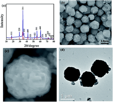
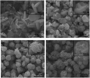
In this study, Zn(CH3COO)2·2H2O and SnCl4·5H2O are used as precursors in the hydrothermal process. The phase structures of prepared samples are characterized by XRD. As shown in Fig. 1a, all peaks are well consistent with pure cubic structure of Zn2SnO4 with the lattice constants of a = b = c = 8.657 Å (JCPDS No. 24-1470). And the strong signal of characteristic peaks indicates the high crystallinity of as-prepared Zn2SnO4 microspheres. As seen in Fig. 1b, the obtained Zn2SnO4 microspheres have a uniform size distribution with diameter of 1.20 μm. Fig. 1c shows the hierarchical structure of as-prepared Zn2SnO4 microsphere with a relatively rough surface. Specifically, the microsphere composes of numerous cross-linked and interconnected nanosheets. Fig. 1d confirms the microscale of the Zn2SnO4 spheres.The time-dependent experiments are carried out to explore the detail formation process of the hierarchical Zn2SnO4 microspheres. As shown in Fig. 2, the morphologies of the Zn2SnO4 are delicately dependent on the hydrothermal reaction time. An interesting morphological evolution has been observed (Fig. 2, 1b and c) since reaction time increased from 1 h to 24 h. At the early stage (1 h), the Zn2SnO4 nanoplates are observed (Fig. 2a). Increasing the time to 2 h, the primary nanoplates occur to connect with each other to form a cross-shaped Zn2SnO4 structure (Fig. 2b). Prolonging the hydrothermal reaction time to 4 h, one can observe the formation of the irregular Zn2SnO4 hemispheres (∼0.6 μm in diameter), which consist of numerous interconnected nanosheets (Fig. 2c). The semi-matured hierarchical Zn2SnO4 microspheres (∼1.0 μm in diameter) can be obtained when the hydrothermal reaction increases to 12 h, as shown in Fig. 2d. Further increasing the hydrothermal time to 24 h leads to the formation of well-defined hierarchical Zn2SnO4 microspheres (∼1.20 μm in diameter) which are made up of cross-linked and interconnected nanosheets (Fig. 1b and c).
Based on the above discussion, a possible growth process of the hierarchical Zn2SnO4 microspheres is proposed (Scheme 1). During the initial stage, the Zn and Sn precursor results in the self-assembly formation of primary Zn2SnO4 nanoplates, and then the cross-shaped Zn2SnO4 structure is formed via the interconnection between nanoplates. With further aggregation of these Zn2SnO4 nanoplates, an irregular Zn2SnO4 hemisphere is formed. Gradually, the newly formed nanoplates selectively attach onto the surface of existing secondary structure, which evolves to the final 3D hierarchical Zn2SnO4 microspheres via the self-assemble process.
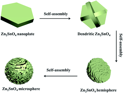 | ||
| Scheme 1 Schematic illustration of the formation process of the as-prepared hierarchical Zn2SnO4 microspheres. | ||
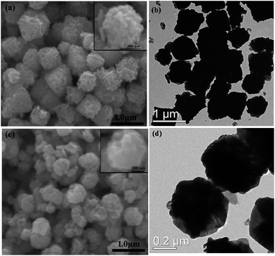
The preliminary study proved the diethylene glycol (DEG) can influence the sizes of the samples.8 Hence, in order to tune the diameter of the hierarchical Zn2SnO4 microspheres, DEG and EG are used as the mixed solvent to support the Zn2SnO4 crystal growth. Meanwhile, it is found that the composition of solvent significantly affects the sizes of Zn2SnO4 microspheres. The FE-SEM and TEM images of the Zn2SnO4 spheres prepared under the different solvent conditions, as shown in Fig. 3. Typically, EG/H2O (20![[thin space (1/6-em)]](https://www.rsc.org/images/entities/char_2009.gif) :
:![[thin space (1/6-em)]](https://www.rsc.org/images/entities/char_2009.gif) 60 in volume ratio) and DEG/H2O (20
60 in volume ratio) and DEG/H2O (20![[thin space (1/6-em)]](https://www.rsc.org/images/entities/char_2009.gif) :
:![[thin space (1/6-em)]](https://www.rsc.org/images/entities/char_2009.gif) 60 in volume ratio) lead to the formation of hierarchical Zn2SnO4 microspheres with average size of 0.85 μm and 0.60 μm, respectively, which are smaller than that of pure H2O-based counterpart (1.20 μm). According to the previous investigation results, the growth rates of crystals vary along the different crystallographic directions, so that the final morphology is controlled by the fastest growth plane.19 The influences of EG and DEG on the sizes of hierarchical Zn2SnO4 microspheres may be attributed to their coordination ability with initial Zn and Sn precursor as well as their reactivity, which can alter the Zn2SnO4 nuclei and growth rates on the different crystal planes, in other words, leading to different size Zn2SnO4 microspheres. However, further work need to be carried out to studied how EG and DEG exactly effect on the sizes of Zn2SnO4 microspheres.
60 in volume ratio) lead to the formation of hierarchical Zn2SnO4 microspheres with average size of 0.85 μm and 0.60 μm, respectively, which are smaller than that of pure H2O-based counterpart (1.20 μm). According to the previous investigation results, the growth rates of crystals vary along the different crystallographic directions, so that the final morphology is controlled by the fastest growth plane.19 The influences of EG and DEG on the sizes of hierarchical Zn2SnO4 microspheres may be attributed to their coordination ability with initial Zn and Sn precursor as well as their reactivity, which can alter the Zn2SnO4 nuclei and growth rates on the different crystal planes, in other words, leading to different size Zn2SnO4 microspheres. However, further work need to be carried out to studied how EG and DEG exactly effect on the sizes of Zn2SnO4 microspheres.
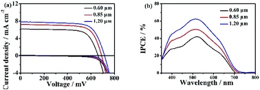
The hierarchical Zn2SnO4 microsphere photoanodes are prepared by screen-printing procedures according to our previous report.12 The photovoltaic properties of DSSCs based on three different sizes hierarchical Zn2SnO4 microspheres are tested by recording the J–V characteristics under AM 1.5 G illumination (100 mW cm−2) conditions. The J–V curves are shown in Fig. 4a and the detailed photovoltaic parameters (Jsc, Voc, PCEs and FF) are summarized in Table 1. The DSSC with 0.60 μm hierarchical Zn2SnO4 microspheres shows the lowest PCE of 2.91% with a Jsc of 6.17 mA cm−2, a Voc of 661 mV and a FF of 0.71. By contrast, the devices based on 0.85 μm hierarchical Zn2SnO4 microspheres shows slightly improved photovoltaic performances with a Jsc of 7.21 mA cm−2, a Voc of 691 mV, a FF of 0.71 and a PCE of 3.56%. The cells based on 1.20 μm hierarchical Zn2SnO4 microspheres shows the best photovoltaic performance with improved Jsc (7.82 mA cm−2), Voc (716 mV) and FF (0.71), leading to an enhanced PCE up to 4.00%. One can see a clear tendency that the Jsc improves with increasing sizes of the hierarchical Zn2SnO4 microspheres. The dark J–V characteristics in Fig. 4 also reveal that the dark photocurrents increase in the order of 1.20 μm Zn2SnO4 microspheres < 0.85 μm Zn2SnO4 microspheres < 0.60 μm Zn2SnO4 microspheres, indicating the suppressed charge recombination along with increased sizes of the hierarchical Zn2SnO4 microspheres.
| DSSCs | Jsc/mA cm−2 | Voc/mV | η/% | FF | Adsorbed dye/× 10−8 mol cm−2 |
|---|---|---|---|---|---|
| 0.60 μm | 6.17 | 661 | 2.91 | 0.71 | 20.16 |
| 0.85 μm | 7.21 | 691 | 3.56 | 0.71 | 19.87 |
| 1.20 μm | 7.82 | 716 | 4.00 | 0.71 | 18.62 |
The incident photon-to-current efficiency (IPCE), defined as the number of electrons generated by light in the external circuit divided by the number of incident photons, is plotted as a function of excitation wavelength, which shows the maximal value at 530 nm increase with the increasing microspheres size (Fig. 4b), which is consistent with the Jsc and η.
The loading amount of N719 dye decreases with increasing sizes of the hierarchical Zn2SnO4 microspheres due to the decreased surface area of the larger microspheres. In addition to the N719 dye loading amount, as well known that, the light scattering ability of the Zn2SnO4 photoanodes can also influence the light utilization capability through altering the path and/or extending the distance of light travelled, and in this way, the light-harvesting efficiency is improved, which would leading to an enhancement of the Jsc and thus PCE.
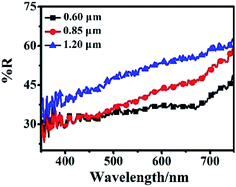
The light scattering ability of three different sizes of the hierarchical Zn2SnO4 microspheres films is determined by diffused reflectance spectroscopy, as shown in Fig. 5. For the larger-sized hierarchical Zn2SnO4 microspheres, the reflectance increases in the whole visible range (500–800 nm), indicating stronger light scattering ability which could maximize the utilization of incident light, thus enhancing the light harvesting efficiency and Jsc. Accordingly, the 1.20 μm Zn2SnO4 microspheres exhibits the best light scattering capability, which is in good agreement with its highest Jsc (7.82 mA cm−2).
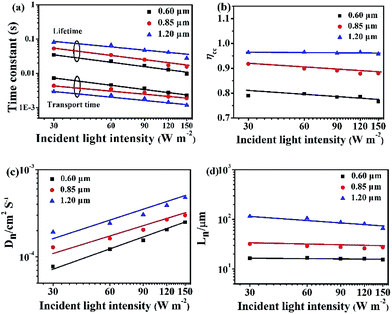
In Fig. 6, the IMPS and IMVS are performed to determine the electron transport and recombination characteristics of the devices based on the three different Zn2SnO4 photoanodes. The detailed parameters extracted from IMPS and IMVS measurements are summarized in Table 2 (light intensity: 150 W m−2). The electron transport time (τd) or recombination time (τr) is obtained from the expression τd = 1/2πfd or τr = 1/2πfr, respectively, where fd or fr is the characteristic frequency minimum of the IMPS/IMVS imaginary component. The τd and τr (Fig. 6a) decreases with increasing light intensity because the deep traps are filled by the more photo-electrons generated at higher light intensity, resulting in electron trapping/detrapping involved shallower levels.20 As summarized in Table 2, the 1.20 μm Zn2SnO4 microspheres exhibits the shorter electron transport time (1.17 ms) than the 0.85 μm Zn2SnO4 microspheres (1.88 ms) and the 0.60 μm Zn2SnO4 microspheres (2.25 ms), implying that the 1.20 μm Zn2SnO4 microsphere is more efficient in terms of electron transport than smaller sized Zn2SnO4 microspheres. In contrast, the electron lifetime of the 1.20 μm Zn2SnO4 microspheres (27.76 ms) is longer than the 0.85 μm Zn2SnO4 microspheres (15.67 ms) and the 0.60 μm Zn2SnO4 microspheres (9.63 ms), indicating much more suppressed charge recombination within larger sized microspheres-based devices than the small microspheres-based counterpart, thus leading to enhanced Voc (716 mV) for the former.
| DSSCs | τd (ms) | τr (ms) | ηcc/% | Dn (cm2 s−1) | Ln (μm) |
|---|---|---|---|---|---|
| 1.20 μm | 1.17 | 27.76 | 95.8 | 4.79 × 10⁻⁴ | 65.6 |
| 0.85 μm | 1.88 | 15.67 | 88.0 | 3.00 × 10⁻⁴ | 27.3 |
| 0.60 μm | 2.25 | 9.63 | 76.6 | 2.49 × 10⁻⁴ | 15.5 |
According to the τd and τr, one can further acquire another important parameter of the DSSCs, namely, electron collection efficiency (ηcc, ηcc = 1 − τd/τr).21,22 Fig. 6b shows the ηcc of the DSSCs based on three different sized hierarchical Zn2SnO4 photoanodes. It is clear that the ηcc of 1.20 μm Zn2SnO4 microspheres-based device (95.8%) is much superior to the 0.85 μm Zn2SnO4 microspheres (88.0%) and 0.60 μm Zn2SnO4 microspheres-based counterparts (76.6%). Herein, the higher ηcc also contributes to the higher Jsc for DSSCs based on 1.20 μm Zn2SnO4 microspheres.
Moreover, the effective electron diffusion length (Ln) can suggest if the injected electron can transport to external circuit through the photoanode film. At the same time, the Ln can influence the Jsc and η. The Ln can be obtained according to the followed equation: Ln = (Dn × τr)1/2, where Dn = d2/(4 × τd), Dn is the electron diffusion coefficient and d is the Zn2SnO4 film thickness. As shown in Fig. 6c and Table 2, along with the increasing spherical diameter, the Dn increases, suggesting that the electron diffusion is faster in Zn2SnO4 microspheres with larger size.
Based on the Dn (Fig. 6c) and τr (Fig. 6a), Ln can be calculated. The DSSCs based on 1.20 μm hierarchical Zn2SnO4 microspheres (65.6 μm) is longer than 0.85 μm hierarchical Zn2SnO4 microspheres (27.3 μm) and 0.60 μm hierarchical Zn2SnO4 microspheres (15.5 μm), implying that the photogenerated electrons can travel through a longer distance within the hierarchical Zn2SnO4 microspheres film (∼1.20 μm in diameter), which in turn, guarantees a better charge collection efficiency for such devices.
Based on the discussion above, the enhancement of Jsc, Voc and PCE of 1.20 μm hierarchical Zn2SnO4 microspheres-based DSSCs devices due to it's superior light scattering, fastest electron transport rates and slowest electron recombination rates.
EIS is a powerful tool to investigate the electrochemical and photoelectrochemical kinetics processes, which can be used to measure the charge transport dynamics of the present DSSCs based on hierarchical Zn2SnO4 microspheres with different sizes. The Nyquist plots of the EIS are shown in Fig. 7. Typically, two semicircles are observed, which can provide good understanding and additional information on the interfacial transfer of photoexcited electrons in the present DSSCs. Generally, the first small semicircle (located in 1 kHz to 1 MHz) corresponds to the charge-transfer resistance at the interface between redox electrolyte/Pt counter electrode. One can see a similar value of resistance because of the utilization of the same electrolyte and counter electrode within the three Zn2SnO4 DSSCs. The second large semicircle (located in 0.1–1 kHz) is attributed to the recombination resistance across the Zn2SnO4/redox electrolyte interface.12 It is found that the recombination resistance (R2, obtained from Z-view software) increases gradually from 92.3 Ω to 268.6 Ω, when the sizes of hierarchical Zn2SnO4 microsphere size increases from 0.60 μm to 1.20 μm. And the electron lifetime of 1.20 μm Zn2SnO4 microspheres, 0.85 μm Zn2SnO4 microspheres and 0.60 μm Zn2SnO4 microspheres-based devices is 28.12 ms, 15.78 ms and 9.89 ms, respectively. Obviously, 1.20 μm Zn2SnO4 microspheres-based devices exhibit the longest electron lifetime, suggesting that the back reaction (between the injected electrons and the I3− in the electrolyte) is inhibited more effectively. In this case, the highest Voc is observed. Notably, the electron lifetime variation and tendency obtained from the EIS is consistent with the aforementioned IMVS data as well.
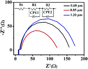 | ||
| Fig. 7 The impedance spectra (Nyquist plots) of DSSCs based on the three different hierarchical Zn2SnO4 photoanodes with a film thickness of ∼15 μm measured at −0.7 V bias in the dark. | ||
The conduction band (CB) potential of TiO2 is negative than Zn2SnO4. Zn2SnO4@TiO2 core–shell structure can not only facilitate the electron transfer from TiO2 to Zn2SnO4, but also can suppress the recombination rates between the photoinjected electrons in the CB of Zn2SnO4 and I3− in the electrolyte, leading to improved ηcc, and thus further increasing the Jsc, Voc and PCE.10,12 In this study, the coating of TiO2 shell on Zn2SnO4 film is achieved via immersing the Zn2SnO4 films into TiCl4 aqueous solution (40 mM) to form the Zn2SnO4@TiO2 core–shell structure (Fig. 8). As for the DSSCs based on Zn2SnO4@TiO2 core–shell structure, the Jsc increases from 7.82 mA cm−2 to 8.96 mA cm−2, and Voc increases from 716 mV to 740 mV. This results in a 25% improvement of PCE from 4.00% to 4.72%, which can be attributed to the significant reduction of the back reaction of the photoinjected electrons from Zn2SnO4 microspheres to the redox electrolyte (I3−). Another possible reason of the improvement is that defects at the internal surface can be minimized while the TiO2 coating on the Zn2SnO4 microspheres surface, which facilitates the electron transfer from N719 dye molecules to the TiO2 and the Zn2SnO4 microspheres. Meanwhile, the modification of TiO2 shell layer could avoid the presence of extra internal trap sites in a poorly constructed junction on Zn2SnO4 microspheres.23
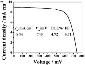 | ||
| Fig. 8 J–V characteristic of DSSCs based on the ∼15.0 μm thick hierarchical Zn2SnO4 microspheres (1.20 μm) coated with the TiO2 shell. | ||
4. Conclusions
In summary, a one-step hydrothermal route is demonstrated to the controllable synthesis of 3D hierarchical Zn2SnO4 microspheres. We proposed a plausible self-assembly formation process of Zn2SnO4 microspheres based on the time-dependent morphological evolution observations. When applied as photoanodes in DSSCs, the 1.20 μm Zn2SnO4 microspheres show the best photovoltaic performance with a PCE of 4.00%. TiCl4 treatment results in the formation of Zn2SnO4@TiO2 core–shell structured photoanode, which further improve the PCE up to 4.72%. The designed 3D hierarchical Zn2SnO4 microspheres with promising optical and electrical properties can be extended to other energy-related applications such as in Li-ion battery, photocatalysis and supercapacitor.Conflicts of interest
There are no conflicts to declare.Acknowledgements
The authors acknowledge the financial supports from the National Natural Science Foundation of China (51502205), Application Development Foundation of Tianjin Normal University (52XK1508), Scientific Research Foundation of Tianjin Normal University (5RL131), and National Training Program of Innovation and Entrepreneurship for Undergraduates in Tianjin of China (201610065012.00) and Academic Innovation Funding of Tianjin Normal University (52XC1404).Notes and references
- B. O'Regan and M. Grätzel, Nature, 1991, 353, 737–740 CrossRef.
- M. Grätzel, Nature, 2001, 414, 338–344 CrossRef PubMed.
- K. Kakiage, Y. Aoyama, T. Yano, K. Oya, J. Fujisawa and M. Hanaya, Chem. Commun., 2015, 51, 15894–15897 RSC.
- S. Colodrero, A. Mihi, L. Häggman, M. Ocaña, G. Boschloo, A. Hagfeldt and H. Mĺguez, Adv. Mater., 2009, 21, 764–770 CrossRef CAS.
- D. H. Chen, F. Z. Huang, Y. B. Cheng and R. A. Caruso, Adv. Mater., 2009, 21, 2206–2210 CrossRef CAS.
- M. Ye, D. Zheng, M. Lv, C. Chen, C. Lin and Z. Lin, Adv. Mater., 2013, 25, 3039–3044 CrossRef CAS PubMed.
- W. Q. Wu, Y. F. Xu, C. Y. Su and D. B. Kuang, Energy Environ. Sci., 2014, 7, 644–649 CAS.
- Y. F. Wang, K. N. Li, C. L. Liang, Y. F. Hou, C. Y. Su and D. B. Kuang, J. Mater. Chem., 2012, 22, 21495–21501 RSC.
- Z. Dong, X. Lai, J. E. Halpert, N. Yang, L. Yi, J. Zhai, D. Wang, Z. Tang and L. Jiang, Adv. Mater., 2012, 24, 1046–1049 CrossRef CAS PubMed.
- Y. F. Wang, K. N. Li, Y. F. Xu, H. S. Rao, C. Y. Su and D. B. Kuang, Nanoscale, 2013, 5, 5940–5948 RSC.
- Z. Li, Y. Zhou, C. Bao, G. Xue, J. Zhang, J. Liu, T. Yu and Z. Zou, Nanoscale, 2012, 4, 3490–3494 RSC.
- S. H. Choi, D. Hwang, D. Y. Kim, Y. Kervella, P. Maldivi, S. Y. Jang, R. Demadrille and I. D. Kim, Adv. Funct. Mater., 2013, 23, 3146–3155 CrossRef CAS.
- T. J. Coutts, D. L. Young, X. Li, W. P. Mulligan and X. J. Wu, J. Vac. Sci. Technol., A, 2000, 18, 2646–2660 CAS.
- Q. F. Zhang, C. S. Dandeneau, X. Y. Zhou and G. Z. Cao, Adv. Mater., 2009, 21, 4087–4108 CrossRef CAS.
- Q. F. Zhang and G. Z. Cao, Nano Today, 2011, 6, 91–109 CrossRef CAS.
- S. So, I. Hwang and P. Schmuki, Energy Environ. Sci., 2015, 8, 849–854 CAS.
- J. Dou, Y. F. Li, F. Y. Xie, X. K. Ding and M. D. Wei, Cryst. Growth Des., 2016, 16, 121–125 CAS.
- Z. Q. Li, Y. P. Que, L. E. Mo, W. C. Chen, Y. Ding, Y. M. Ma, L. Jiang, L. H. Huand and S. Y. Dai, ACS Appl. Mater. Interfaces, 2015, 7, 10928–10934 CAS.
- Y. J. Xiong, H. G. Cai, B. J. Wiley, J. G. Wang, M. J. Kim and Y. N. Xia, J. Am. Chem. Soc., 2007, 129, 3665–3675 CrossRef CAS PubMed.
- T. Oekermann, T. Yoshida, H. Minoura, K. G. U. Wijayantha and L. M. Peter, J. Phys. Chem. B, 2004, 108, 8364–8370 CrossRef CAS.
- K. Zhu, N. R. Neale, A. Miedaner and A. J. Frank, Nano Lett., 2007, 7, 69–74 CrossRef CAS PubMed.
- T. Oekermann, D. Zhang, T. Yoshida and H. Minoura, J. Phys. Chem. B, 2004, 108, 2227–2235 CrossRef CAS.
- H. J. Snaith and C. Ducati, Nano Lett., 2010, 10, 1259–1265 CrossRef CAS PubMed.
Footnote |
| † Electronic supplementary information (ESI) available. See DOI: 10.1039/c7ra06906e |
| This journal is © The Royal Society of Chemistry 2017 |

