 Open Access Article
High temperature resistant polysulfone/silica double-wall microcapsules and their application in self-lubricating polypropylene
Haiyan Li a,
Yingjie Maa,
Zhike Lia,
Jing Jib,
Yanji Zhua and
Huaiyuan Wang*a
aProvincial Key Laboratory of Oil & Gas Chemical Technology, College of Chemistry & Chemical Engineering, Northeast Petroleum University, Daqing 163318, PR China. E-mail: wanghyjiji@163.com; Tel: +86-459-6503083
bHeilongjiang Key Laboratory of Disaster Prevention, Mitigation and Protection Engineering, College of Civil and Architecture Engineering, Northeast Petroleum University, Daqing 163318, PR China
First published on 30th October 2017
Abstract
Polysulfone (PSF)/silica hybrid double-wall microcapsules containing lubricant are synthesized. The lubricant-loaded PSF microcapsules are prepared by a simple solvent evaporation method, and the surface of the PSF microcapsules are modified and activated by dopamine. The activated PSF microcapsules are then microencapsulated again by a silica wall using a sol–gel method. The mean diameter and wall thickness of the synthesized double-wall microcapsules are approximately 90 and 6 μm, respectively. High thermal stability of the microcapsules with a thermal degradation onset temperature of 300 °C is obtained. The microcapsules are able to withstand the high-temperature shaping conditions necessary for the polypropylene (PP) composites system used (260 °C for 60 min). The silica walls effectively protect the PSF microcapsules from softening transformation. Tribology testing of PP self-lubricating composites incorporating 10 wt% lubricant-loaded microcapsules yields 54.9% and 54.3% reductions in the coefficient friction and wear rate under middle load and middle sliding speed conditions, respectively, compared to the pure PP. The tribological behavior of the self-lubricating PP is further assessed under different applied loads and sliding speed combinations. The formation of a boundary lubricating film from releasing lubricant and the entrapment of wear debris in the cavities left by the ruptured microcapsules are the major self-lubricating mechanisms. These PSF/silica hybrids double-wall microcapsules can be applied to many other polymers to produce unique self-lubricating materials.
1. Introduction
In recent years, there have been three major methods for fabricating self-lubricating polymer composites. The first method is to incorporate solid lubricant into a polymer. These solid lubricant fillers, including fibers,1 carbon nanotubes,2 graphite,3 polytetrafluoroethylene,4 WS2 (ref. 5) and MoS2,6 can enhance the wear resistance of polymer composites by improving the mechanical properties. However, high prices and difficult dispersion and processing of these solid lubricant fillers limit their application. The second method is to make nano/micropores in the polymer matrix and then inject liquid lubricant into these pores to prepare porous self-lubricating materials.7–13 These pore-structure materials can be filled, in situ, with ionic liquid, silicone oil and lithium grease, and have excellent tribological performance. During the sliding friction process, porous composites are subjected to friction and the liquid lubricant pre-stored in the pore structure can be extruded to form a lubricating film on the friction surface to prevent direct friction between composites and friction pairs. However, the oil leak phenomenon is the major weakness and limits its application. The third method is to incorporate lubricant-loaded microcapsules into a polymer matrix. When the pre-embedded microcapsules are broken during repeated friction processes, the liquid lubricant can be released to the wear surface, which significantly enhances the frictional resistance properties.The fabrication of self-lubricating materials by incorporating lubricant-loaded microcapsules has been reported widely. In self-lubricating materials systems, paraffin wax,14–17 lubricant oil,18–20 sulfureted fatty acids,21 hexamethylene diisocyanate22 and ionic liquids23 have been used as lubricants and microencapsulated. Frequently-used wall materials include poly(urea-formaldehyde) (PUF), poly(melamine-formaldehyde) (PMF) and polyurea (PU).19,20,24 These wall materials are brittle and easily broken in the fabrication process of composites. In addition, their thermal decomposition temperature is in the range of 200–240 °C, which limits their application in high temperature environments. The above mentioned microcapsules were incorporated into an epoxy matrix to prepare self-lubricating composites. The operating temperature of the epoxy composite was in the range of room temperature to 120 °C. No literatures reported that the microcapsules were applied in polymer materials with high forming temperature (>200 °C) because the limited thermal stability of above microcapsules. Recently, we have demonstrated the encapsulation of a lubricant, ionic liquid and tung oil by solvent evaporation method.18,25,26 Polysulfone (PSF) was used as the wall material of microcapsules and the synthesized microcapsules were applied in an epoxy resin to prepare self-lubricating and self-healing materials. PSF has high chemical and physical stability, excellent mechanical properties and thermal stability (its thermal decomposition temperature is 490–510 °C). However, the low softening temperature of PSF (170 °C) makes it unsuitable for applications in high-temperature conditions. Recently, the use of SiO2 as a wall material for microcapsules has been reported, with excellent thermal stability being its most attractive advantage. In this reports, the SiO2 shell was formed via interfacial hydrolysis and polycondensation of tetraethoxysilane by interfacial polymerization, or combined with in situ polymerization in order to increase the wall thickness because a thicker silica shell is unachievable via a single interfacial polymerization route.27–30 However, it is difficult to control the morphology, wall thickness and diameter of microcapsules based on interfacial polymerization and in situ polymerization.
In this study, organic (PSF)/inorganic (SiO2) hybrid double-wall microcapsules containing lubricant oil were prepared by a simple method. First, a solvent evaporation method is used to prepare PSF microcapsules. The wall thickness, core content and diameter of the microcapsules can be easily controlled. The PSF microcapsule surfaces are activated by dopamine, and then the SiO2 shell is formed on the activated PSF microcapsules by sol–gel methods. The wall materials combined the excellent mechanical properties of PSF and the high thermal stability of SiO2. The synthetic microcapsules shown excellent high temperature resistant performance and can be applied in the surrounding of higher temperature. We incorporated the double-wall microcapsules into polypropylene (PP) to prepare self-lubricating composites at a high thermoforming temperature condition (260 °C). The self-lubricating properties of PP composites are evaluated by tribological tests.
2. Experimental
2.1 Materials
Lubricant oil (70SN, density = 0.82 g cm−3) was supplied by Daqing Oil Field Co. Ltd (China). PSF (P-7304, η = 0.45–0.65) was purchased from Dalian PSF Technology Co. Ltd (China). Dichloromethane (DCM, >99.5 wt%) and polyvinyl alcohol (PVA) (degree of polymerization = 1750 ± 50) were purchased from Tianjin Damao Co. (China). Gelatin (>99 wt%) was obtained from Tianjin Zhiyuan Chemical Reagents Co. Ltd (China). Tetraethoxysilane (TEOS) was purchased from Aladdin. Dopamine and tris(hydroxymethyl)aminomethane hydrochloride (Tris–HCl) were bought from Suzhou Tianke Trade Co. Ltd (China). Ethanol and ammonium hydroxide (NH3·H2O) were supplied by Huadong Reagent Factory, Shenyang (China). Polypropylene (PP-H-XD-045) was supplied by Daqing Petrochemical Research Center (China). Deionized water was used throughout the study. All materials were used as received without any further purification.2.2 Synthesis of PSF/SiO2 double-wall microcapsules containing lubricant oil
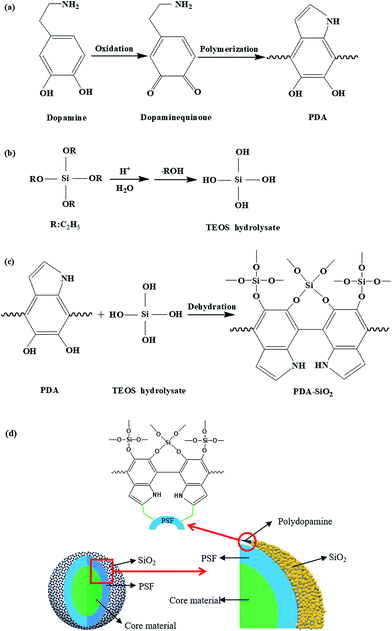
Fig. 1 schematically illustrates the detailed process for fabricating the PSF/silica double-wall microcapsules containing lubricant oil. First, lubricant oil-loaded PSF microcapsules were prepared by a solvent evaporation method according to our previous report.18 Second, in order to activate the PSF microcapsules, polydopamine was synthesized on the PSF microcapsule surfaces by the self-polymerization of dopamine. The synthesized PSF microcapsules (2 g) were dispersed in a dopamine solution (100 mL, solution concentration = 1.2 g L−1), before Tris–HCl (0.12 g) was added to adjust the pH of the solution. Dopamine began to self-polymerize under room temperature conditions with 24 h of magnetic stirring at 300 rpm. By filtering and drying, the activated PSF microcapsules were obtained. Third, the silica wall was prepared by using sol–gel techniques. Ethanol (100 mL) and NH3·H2O (10 mL) were mixed to form uniform solution A, and TEOS (10 mL) was mixed with ethanol (10 mL) to form solution B. The activated PSF microcapsules (1 g) were added to solution A. Solution B was then dropped slowly into mixed solution A. The resulting mixture was stirred at 60 °C for 12 h. PSF/silica double-wall microcapsules were obtained. The resulting PSF/silica microcapsules were separated and washed with ethanol three times, then were dried in an oven at 60 °C for 5 h.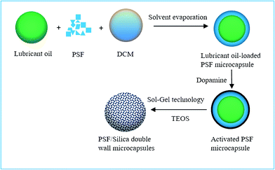 | ||
| Fig. 1 The fabricate process schematic of PSF/SiO2 double-wall microcapsules containing lubricant oil. | ||
2.3 Preparation of self-lubricating polypropylene
Polypropylene-based self-lubricating composites were manufactured by mixing the polypropylene powder with 0–20 wt% synthesized microcapsules at room temperature, the mixture was then heated to 260 °C in a vacuum drying oven with 2 °C min−1 heating rate. After 30 min, the mixture was cooled to room temperature and the self-lubricating polypropylene composites were achieved.2.4 Characterizations
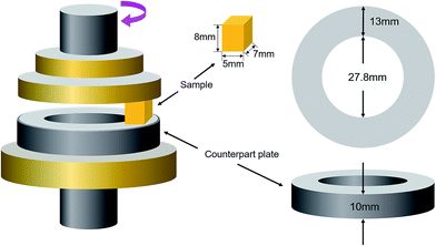
The thermal stability of the lubricant oil-loaded microcapsules was evaluated using thermogravimetric analysis (TGA). Measurements were carried out over a 25–800 °C temperature range at a heating rate of 10 °C min−1 under N2 atmosphere. The morphology of the microcapsules and the worn surface were observed by Scanning Electron Microscopy (SEM) with an Energy Dispersive Spectrometer (EDS). The chemical structures of PSF microcapsules, dopamine-functionalized microcapsules, PSF/SiO2 double-wall microcapsule were analyzed by Fourier Transform Infrared Spectrometer (FTIR) in the wavenumber range of from 4000 to 500 cm−1. The mean diameter and shell thickness of PSF/SiO2 microcapsules was investigated in date sets of at least 200 measurements measured with SEM. Before shell thickness measure, the PSF/SiO2 microcapsules were dispersed into epoxy and cured at room temperature for 6 h and then 80 °C 6 h, the epoxy composites containing microcapsules were placed into liquid nitrogen for 1 min, and then fracture the composites by clamps, the fracture surfaces were observed by SEM, the shell thickness of PSF/SiO2 microcapsules was calculated.The tribological behaviors of the polypropylene composites was examined by friction and wear tests. A schematic diagram of the friction and wear tests with pin-on-disc configuration are presented in Fig. 2. The applied loads were 0.5 MPa, 1.0 MPa and 1.5 MPa, the sliding velocities were 0.5 m s−1, 0.75 m s−1 and 1.0 m s−1. The friction duration was 30 min. The friction coefficient and wear rate were calculated by the equation given in our previous study.31 Before each test, the surfaces of counterpart plate and specimen were polished with 1000-grit paper to an average roughness of 0.15–0.3 μm and then cleaned with anhydrous ethanol. Tensile tests of the composite samples were performed on a universal tester according to ASTM D638-10. All tests were conducted under ambient laboratory conditions. Three measurements per sample were taken to get the mean and standard deviation.
3. Results and discussion
3.1 The formation of PSF/silica double-wall structure
The PSF microcapsules containing lubricant oil was prepared according to our previous study.18 In this work, dopamine was selected to enhance the adhesion between PSF microcapsules and SiO2 particles. Fig. 3 shows the forming progress of the PSF/silica double-wall structure. Through the self-polymerization of dopamine (Fig. 3(a)), highly reactive hydroxyl groups can be wrapped on the surface of PSF microcapsules. The SiO2 particles derived from the hydrolysis of TEOS (Fig. 3(b)) connect with the hydroxyl groups of poly-dopamine by the covalent bonds (Fig. 3(c)), and then PSF/silica double-wall structure was formed (Fig. 3(d)).3.2 Microscopic morphological characteristics of microcapsules
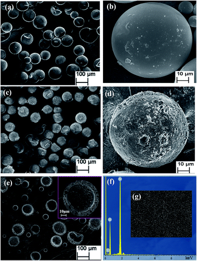
Fig. 4(a) shows the SEM micrographs of the lubricant-loaded PSF microcapsules. Fig. 4(b) is a single PSF microcapsule micrograph at high magnification. The synthetic PSF microcapsules presented regular, compact and spherical structures with smooth outside surfaces. The average diameter of the particles was approximately 90 μm. Fig. 4(c) shows the SEM micrographs of the lubricant-loaded PSF/SiO2 double-wall microcapsules and Fig. 4(d) is their magnified SEM micrograph. Compared with PSF microcapsules, the surface of the PSF/SiO2 double-wall microcapsules shows a rough structure, which is attributed to the sediment of SiO2 in the surface PSF wall of the microcapsules. Fig. 4(e) shows a ruptured microcapsule with a uniform shell wall thickness of approximately 6 μm. Fig. 4(f) shows the EDS spectrum of a microcapsule surface. Silicon and oxygen, the characteristic elements of SiO2, are present in the microcapsules surface. The sulfur of the PSF molecular was not been found in the EDS spectrum, which indicates that the SiO2 have been deposited in the surface of microcapsules by the hydrolysis and sedimentation of TEOS. Fig. 4(g) further shows the Si elemental distribution in the microcapsule surface. The uniform distribution confirms that the PSF wall was coated by the SiO2 and the double-wall structure of the microcapsules had been formed.3.3 Chemical composition of microcapsules
The FTIR curves of PSF microcapsules, dopamine-functionalized microcapsules and PSF/SiO2 double-wall microcapsule were plotted in Fig. 5. Compared the FTIR curves, the dopamine-functionalized microcapsules shown a broad characteristic peaks at ≈3440 cm−1, which are the stretching vibration peak of O–H and N–H groups derived from poly-dopamine. The FTIR cure of PSF/SiO2 double-wall microcapsule shown the strong characteristic peaks of SiO2 at ≈1080 cm−1 (Si–O–Si asymmetric stretching) and poly-dopamine at ≈3440 cm−1 (N–H and unreacted O–H stretching vibration). The infrared spectroscopy curves verified that dopamine self-polymerize on PSF microcapsules surface, and also confirm the SiO2 particles deposit on the dopamine-functionalized microcapsules surface.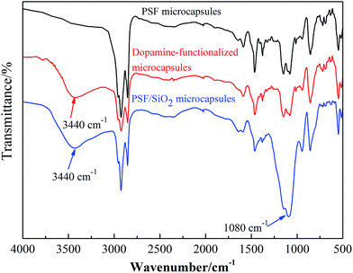 | ||
| Fig. 5 FTIR spectra of PSF microcapsules, dopamine-functionalized microcapsules, and PSF/SiO2 double-wall microcapsule. | ||
3.4 Thermal stability of microcapsules
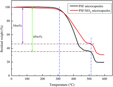
The thermal stability of the PSF microcapsules and PSF/SiO2 microcapsules were analyzed and the results are shown in Fig. 6. The initial decomposition temperature of the PSF microcapsules and PSF/SiO2 microcapsules was 305 °C, which is attributed to the evaporation of the lubricant. The process was completed at 450 °C. The value is higher than those of microcapsules reported in the literature, such as PUF microcapsules (240 °C),19 PU microcapsules (200 °C)24 and PMF microcapsules (260 °C).20 For the two kinds of microcapsules, when the temperature reached 510 °C, the PSF wall began to decompose. There was 20 wt% residual weight for the PSF microcapsules, probably due to the formation of thermally stable carbonaceous materials because of the presence of aromatic structures in the PSF polymer backbone.23 For the PSF/SiO2 microcapsules, the residual weight was 31 wt%, which was attributed to the undecomposed PSF and SiO2 wall. The slope of the TG curve of the PSF/SiO2 microcapsules was smaller than for the PSF microcapsules. This result indicates that the SiO2 shell should act as a protective thermal barrier and retard the escaping of the lubricant. The encapsulation capacity of the PSF microcapsules was 65 wt%, which was calculated from the TG curve. When the PSF microcapsules were coated by the SiO2 wall, the encapsulation capacity changed to 54 wt%.Fig. 7 shows the macro thermal properties of the PSF microcapsules (no. 1) and PSF/SiO2 double-wall microcapsules (no. 2) under different temperatures. At room temperature, the PSF microcapsules and PSF/SiO2 double-wall microcapsules show white and black brown particles, respectively. When the microcapsules were heated to 170–200 °C, the PSF microcapsules began to soften and turn to yellow. At 250 °C, PSF microcapsules fully softened into a yellow fluid. Upon increasing the temperature to 300 °C, the PSF microcapsules started to decompose and present a black fluid. The above phenomena indicate that the usage temperature of PSF microcapsules should be below 170 °C. However, for the PSF/SiO2 double-wall microcapsules, when the temperature reached 350 °C, the microcapsules maintained the initial granular particle state. Combining the TGA results, the PSF/SiO2 double-wall microcapsules have excellent thermal stability and can be used safely below 300 °C.
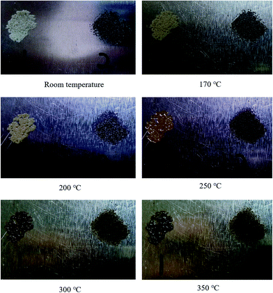 | ||
| Fig. 7 The macroscopic thermal properties of PSF microcapsules and PSF/SiO2 double-wall microcapsules. | ||
3.5 Self-lubricating properties of the PP composites
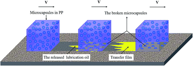
The self-lubricating properties of the PP composites were evaluated by tribology tests. Fig. 8 depicts the frictional coefficient and wear rate of PP composites as a variation of microcapsules content under a normal load of 1.0 MPa and a sliding speed of 0.75 m s−1. It is obvious that the frictional coefficient and wear rate both decrease first and increase later with increasing microcapsule content. The minimum values of the frictional coefficient and wear rate are obtained at a microcapsule content of 10 wt%, which are 54.9% and 54.3% lower than that of pure PP, respectively. This result indicates that 10 wt% lubricant-loaded microcapsules can improve the tribological properties of PP composites. Fig. 9 shows the schematic diagrams of the antifriction mechanism of the self-lubricating PP composites. The incorporated microcapsules ruptured and released the lubricant in the tribological tests and then formed a transfer film that reduced the friction by preventing direct contact between the steel counterpart and PP composites. When the content of the microcapsules continued to increase (>10 wt%), the obvious decrease of mechanical properties will evidently affect the tribological properties of the PP composites. Table 1 shows the mechanical properties of PP composites at different microcapsules contents. With the increase of microcapsules contents, the tensile strength of PP composites decreased. When microcapsules content is greater than 10 wt%, the decreasing tendency become more pronounced. The stiffness and strength of a material is an important parameter for controlling its wear resistance.19 Thus, the frictional coefficient and wear rate exhibit a rising trend. Fig. 10 shows the SEM morphological of tensile fracture surface, microcapsules can be observed in the fracture surface of PP composites containing 10 wt% microcapsules (Fig. 10(b)). Most of microcapsules are cracked which indicates there has excellent interface combine between microcapsules and PP. However, the large size of microcapsules served as an additive certainly brings the obvious decrease of mechanical properties.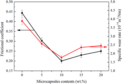 | ||
| Fig. 8 Frictional coefficients and specific wear rate of self-lubricant PP composites versus content of the lubricant-loaded microcapsules. | ||
| Microcapsule contents wt% | 0 | 5 | 10 | 15 | 20 |
| Tensile strength MPa | 29.4 ± 1.2 | 26.8 ± 0.9 | 23.9 ± 0.8 | 19.5 ± 1.0 | 12.1 ± 1.6 |
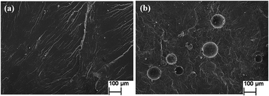 | ||
| Fig. 10 SEM micrographs of tensile fracture surface (a) pure PP (b) PP composite containing 10 wt% microcapsules. | ||
The frictional coefficient and wear rate for the different load and speed combinations are investigated. Fig. 11 depicts the variation of friction coefficient and wear rate of the pure PP and its composites as a function of the applied load with a velocity of 0.75 m s−1. It is observed that the friction coefficient and wear rate are both smaller than those of pure PP, which confirms that the lubricant-loaded microcapsules play an important role in the improvement of tribological properties. For pure PP and its composites, the friction coefficient and wear rate decrease as the load increases from 0.5 to 1.0 MPa, which is attributed to the real contact area between the specimen and the counterpart plate being small and unstable under the low applied load, resulting in a high mass loss. This phenomenon weakens when the applied load is increased. Moreover, when the applied load increases from 1.0 to 1.5 MPa, the pure PP specimen cannot endure the friction condition and shows serious plastic deformation due to the large amount of frictional heat. In this condition, the wear rate of PP composites sharply increases because of the same reason. However, the PP composites still can resist the friction condition and no serious plastic deformation phenomenon occurs. The friction coefficient shows a slight increase. This indicates that the wear resistance of the PP composites is significantly improved compared to that of pure PP.
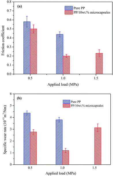 | ||
| Fig. 11 Effect of applied load on (a) the friction coefficient and (b) the wear rate of pure PP and its self-lubricating composites with 10 wt% microcapsules. | ||
Fig. 12 shows the effect of velocity on the friction coefficient and wear rate of pure PP and its composites with a given load of 1.0 MPa. The friction coefficient and wear rate of the composites are both smaller than those for pure PP. It is also clear that the addition of lubricant-loaded microcapsules can improve the tribological properties. When increasing the velocity from 0.5 to 0.75 m s−1, the friction coefficient of pure PP changes minimally. However, the friction coefficient and wear rate of the PP composites obviously decrease, which may be attributed to the release rate of the lubricant. At a 0.5 m s−1 sliding speed, the release rate of the lubricant is insufficient to promote the availability of enough material to form a boundary layer. At a sliding speed of 0.75 m s−1, the high release rate can ensure that enough lubricant is released to form effective boundary lubricant films, which contribute to the obvious decrease in the friction coefficient and wear rate of the PP composites. When the velocity is 1.0 m s−1, more heat is generated in the friction process leading to a higher degree of softening and deformation on the worn surface, and consequently, a higher friction coefficient and wear loss for the PP composites. For the pure PP specimen, the additional wear heat generated results in increasing wear loss from the low velocity to the high velocity, at the 1.0 m s−1 velocity condition, with severe deformation occurring in 10 min and the specimen losing usability. The above results indicate that the additions of lubricant-loaded microcapsules significantly improve the tribological properties of PP.
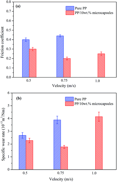 | ||
| Fig. 12 Effect of sliding velocity on (a) the friction coefficient and (b) the wear rate of pure PP and its self-lubricating composites with 10 wt% microcapsules. | ||
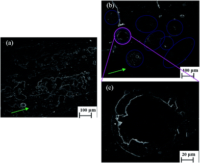
After the tribological tests, the wear surface morphologies of the pure PP and the self-lubricant PP with 10 wt% microcapsules under the sliding condition of 1.0 MPa and 0.75 m s−1 were investigated by SEM, as shown in Fig. 13. It is apparent that the wear surface of pure PP is considerably rough and has a significantly delaminated layer, as shown in Fig. 13(a), as a result of the accumulation and adherence of worn debris due to the plastic deformation generated with the increasing temperature of the wear surface. The wear mechanism of pure PP is mainly adhesion and fatigue wear. Compared to the pure PP, it can be obviously seen that the worn surface of the PP composites in Fig. 13(b) appears to be smooth under the same friction load due to the lubrication of microcapsules. The boundary lubricating films generated in the tribological process play an important role in protecting the worn surface from abrasion. The ruptured microcapsules can trap the wear debris that also contribute to the decrease of the frictional coefficient and wear rate of the PP composites. Cavities representing the ruptured microcapsules are given in Fig. 13(b). The morphologies of the ruptured microcapsules are not regular, which can be attributed to the small degree of softening, deformation and adhesion of thermoplastic PP around the microcapsules. Fig. 13(c) shows a close view of a cavity. It further reveals that the wear debris was trapped by the worn microcapsules. The reduction in the amount of wear debris due to entrapment by the cavities weakened the abrasive effect of the wear debris as a third body in the contact area, which also decreased the frictional coefficient and wear rate.
4. Conclusions
PSF/SiO2 double-wall microcapsules containing lubricant were successfully prepared by a solvent evaporation and sol–gel method. This kind of synthesis method is simple and readily scalable for the production of large quantities of microcapsules. The microcapsules had mean spherical dimeters of approximately 90 μm and a wall thickness of approximately 6 μm. The PSF/SiO2 double-wall microcapsules have the ability to withstand the temperature conditions necessary for PP processing. The self-lubricating PP composites were also fabricated by adding the microcapsules into the PP and the tribological properties were researched in different tribological conditions. When the concentration of microcapsules was 10 wt%, the best tribological properties are obtained under tribological test conditions of 1.0 MPa and 0.75 m s−1. The coefficient friction and wear rate decreased by 54.9% and 54.3% when compared with the pure PP, which was attributed to the formation of a boundary transfer lubricating film during the tribology process. PSF/SiO2 double-wall microcapsules have excellent thermal stability and mechanical properties, and can be applied to many other polymers to prepare self-lubricating composites.Conflicts of interest
There are no conflicts of interest to declare.Acknowledgements
The research is financially supported by the National Young Top Talents Plan of China (2013042), National Science Foundation of China (21676052, 21606042), National Science Foundation of China (51175066), Program for New Century Excellent Talents in University (NCET-12-0704), the Science Foundation for Distinguished Young Scholars of Heilongjiang Province (JC201403), PetroChina Innovation Foundation (2016D-5007-0608), Special Funds for Scientific Research of Heilongjiang Education Department within the Program (2016YSFX-02), and Natural Science Foundation of Heilongjiang Province (E2015034).References
- Y. Wan, H. Luo, Y. Wang, Y. Huang, Q. Li, F. Zhou and G. Chen, J. Mater. Sci., 2005, 40, 4475–4481 CrossRef CAS.
- N. Khun, B. R. Troconis and G. Frankel, Prog. Org. Coat., 2014, 77, 72–80 CrossRef CAS.
- B. Shivamurthy, K. U. Bhat and S. Anandhan, Mater. Des., 2013, 44, 136–143 CrossRef CAS.
- M. K. Dubey, J. Bijwe and S. Ramakumar, Wear, 2013, 306, 80–88 CrossRef.
- G. Ren, Z. Zhang, X. Zhu, M. Yang, X. Men, W. Jiang and W. Liu, J. Mater. Sci., 2015, 50, 1065–1070 CrossRef CAS.
- B. Liu, X. Pei, Q. Wang, X. Sun and T. Wang, Appl. Surf. Sci., 2011, 258, 1097–1102 CrossRef CAS.
- W. Liu, C. Ye, Q. Gong, H. Wang and P. Wang, Tribol. Lett., 2002, 13, 81–85 CrossRef CAS.
- C. Ye, W. Liu, Y. Chen and L. Yu, Chem. Commun., 2001, 21, 2244–2245 RSC.
- X. Fan, Y. Xia, L. Wang, J. Pu, T. Chen and H. Zhang, Tribol. Lett., 2014, 53, 281–291 CrossRef CAS.
- S. S. Yoo and D.-E. Kim, Int. J. Precis. Eng. Man., 2013, 14, 875–880 CrossRef.
- H. Wang, M. Li, D. Liu, Y. Zhao and Y. Zhu, J. Mater. Sci., 2016, 51, 3917–3927 CrossRef CAS.
- H. Wang, D. Liu, L. Yan, C. Wang, S. Yang and Y. Zhu, Tribol. Int., 2014, 77, 43–49 CrossRef CAS.
- H. Wang, D. Liu, L. Yan, M. Li, C. Wang and Y. Zhu, Wear, 2014, 320, 94–102 CrossRef CAS.
- N. W. Khun, H. Zhang, X.-z. Tang, C. Y. Yue and J. Yang, J. Appl. Mech., 2014, 81, 121004 CrossRef.
- N. Khun, H. Zhang, C. Yue and J. Yang, J. Appl. Mech., 2014, 81, 071004 CrossRef.
- N. Khun, H. Zhang, D. Sun and J. Yang, Wear, 2016, 350, 89–98 CrossRef.
- N. W. Khun, H. Zhang, J. Yang and E. Liu, Wear, 2012, 296, 575–582 CrossRef CAS.
- H. Li, Q. Wang, M. Li, Y. Cui, Y. Zhu, B. Wang and H. Wang, J. Microencapsulation, 2016, 33, 286–291 CrossRef CAS PubMed.
- Q. B. Guo, K. T. Lau, B. F. Zheng, M. Z. Rong and M. Q. Zhang, Macromol. Mater. Eng., 2009, 294, 20–24 CrossRef CAS.
- Q. B. Guo, K. T. Lau, M. Z. Rong and M. Q. Zhang, Wear, 2010, 269, 13–20 CrossRef CAS.
- G. Ma, X. Xu, Q. Jin, R. He and J. Guan, Acta Mater. Compositae Sin., 2013, 30, 37–43 CAS.
- N. W. Khun, D. Sun, M. X. Huang, J. L. Yang and C. Y. Yue, Wear, 2014, 313, 19–28 CrossRef CAS.
- P. Bandeira, J. Monteiro, A. M. Baptista and F. D. Magalhães, Tribol. Lett., 2015, 59, 13 CrossRef.
- S. Armada, R. Schmid, S. Equey, I. Fagoaga and N. Espallargas, J. Therm. Spray Technol., 2013, 22, 10–17 CrossRef CAS.
- H. Li, Q. Wang, H. Wang, Y. Cui, Y. Zhu and B. Wang, Macromol. Mater. Eng., 2016, 301, 1473–1481 CrossRef CAS.
- H. Li, Y. Cui, H. Wang, Y. Zhu and B. Wang, Colloids Surf., A, 2017, 518, 181–187 CrossRef CAS.
- E. Weiss, B. Dutta, A. Kirschning and R. Abu-Reziq, Chem. Mater., 2014, 26, 4781–4787 CrossRef CAS.
- M. Yang, X. Zhu, G. Ren, X. Men, F. Guo, P. Li and Z. Zhang, Tribol. Lett., 2015, 58, 9 CrossRef.
- W. Guo, Y. Jia, K. Tian, Z. Xu, J. Jiao, R. Li, Y. Wu, L. Cao and H. Wang, ACS Appl. Mater. Interfaces, 2016, 8, 21046–21054 CAS.
- Y. Jia, H. Wang, K. Tian, R. Li, Z. Xu, J. Jiao, L. Cao and Y. Wu, Int. J. Smart Nano Mater., 2016, 7, 221–235 CrossRef.
- L. Yan, H. Wang, C. Wang, L. Sun, D. Liu and Y. Zhu, Wear, 2013, 308, 105–112 CrossRef CAS.
| This journal is © The Royal Society of Chemistry 2017 |

