
 Open Access Article
 This Open Access Article is licensed under a
 Creative Commons Attribution 3.0 Unported Licence
Synthesis of 3D porous MoS2/g-C3N4 heterojunction as a high efficiency photocatalyst for boosting H2 evolution activity†
Youzhi Cao a,
Qin Gaoc,
Qiao Lia,
Xinbo Jinga,
Shufen Wang*b and
Wei Wang*a
a,
Qin Gaoc,
Qiao Lia,
Xinbo Jinga,
Shufen Wang*b and
Wei Wang*a
aSchool of Chemistry and Chemical Engineering, Key Laboratory for Green Processing of Chemical Engineering of Xinjiang Bingtuan, Shihezi University, Shihezi 832003, China. E-mail: wangwei_group@sina.com
bCollege of Sciences, Shihezi University, Shihezi 832003, China
cKey Laboratory of Synthetic and Natural Functional Molecule Chemistry of Ministry of Education, College of Chemistry and Material Science, Northwest University, Xi'an 710127, P. R. China
First published on 21st August 2017
Abstract
A novel strategy was applied for the preparation of MoS2/graphitic carbon nitride (g-C3N4) with porous morphology. These composites demonstrate a greatly enhanced response to visible light, and remarkably enhanced hydrogen evolution performance by photocatalytic water splitting. Compared to pure g-C3N4, the bulk doping porous MoS2/g-C3N4 (BPMCN) heterojunction photocatalysts exhibit significantly enhanced H2 evolution of 1640 μmol g−1 h−1 under visible light irradiation. The absorption edge is transfered from 455 nm (g-C3N4) to 532 nm (BPMCN-0.7) in the UV-vis diffuse reflectance spectra. Of course, structural, optical and electronic analyses demonstrate that the highly efficient activity of BPMCN is attributed to the enhanced light harvesting by efficient separation of photogenerated electron–hole pairs, and the expansion of the light response range. The present work shows that the formation of 3D heterojunction should be a good strategy to design efficient photocatalysts.
1. Introduction
Hydrogen is regarded as a very significant potential fuel. In particular, with photocatalysis technology development, photocatalytic hydrogen production through water splitting has been considered as a green, pure and high efficient technique and has attracted growing attention in the past few decades. Various kinds of photobased catalysts suitable for natural light have been developed.1–4 Graphitic carbon nitride (g-C3N4), only composed of C and N elements, draws extensive attention due to its potential application in solar energy conversion, electro-catalysis, photo-synthesis, and bio-imaging, with an appropriate bandgap and excellent chemical stability. However, the efficiency of pure g-C3N4 is still far from being satisfactory owing to its small surface area and a high recombination rate of photoinduced electron–hole pairs.5–7Up to now, to improve the efficiency of water-splitting, many strategies including doping with heteroatoms, deposition with metal atoms, coupling g-C3N4 with other semiconductors and two dimensional transition-metal dichalcogenides (TMDC) materials have been developed to improve the overall activity for photocatalytic processes.8–14 One of the most studied members of the TMDC family is molybdenum disulfide (MoS2), owing to its natural abundance, low cost, high chemical stability and good catalytic performance. Recently MoS2 has become a representative non-precious material for photocatalytic hydrogen evolution reaction of water splitting.15–17 Unfortunately, bulk MoS2 has poor conductivity, which is attributed to the lateral transfer of electrons along the layered structure of MoS2 nanosheets.18,19 To date, its potential as a cocatalyst for photocatalytic H2 production has received only sporadic attention even though it has demonstrated high activity in reactions involving H2 under heterogeneous catalysis.20
Porous structures are more attractive due to their outstanding properties of low density and high surface area.21,22 These can optimize the light-harvesting ability, mobility of charge carriers and permeability for mass transport. Therefore, the efficient light-induced redox reaction can be achieved.23 Indeed, porous inorganic structured semiconductor materials (such as TiO2, SnO2, CdS, CdTe, Cu2O, etc.) have exhibited promising applications in the field of photocatalytic water splitting for hydrogen production.24–29
Much work so far has focused on the synthesis of the surface doping MoS2/g-C3N4 photocatalyst for water splitting.8–10,30–34 However, further efforts are required to study the bulk doping MoS2/g-C3N4 for photocatalytic H2 evolution. Herein, we report a facile approach to synthesise porous MoS2/g-C3N4 (BPMCN) heterojunction catalysis for enhancing photocatalytic hydrogen evolution. The synthetic process is illustrated in Fig. 1 with two steps: (1) preparation of mixed precursors using freeze drying; (2) annealing of mixed precursors at 600 °C to obtain porous MoS2/g-C3N4 heterojunction photocatalysts. 3D porous MoS2/g-C3N4 samples display enhanced photoabsorption, efficient charge separation and much higher photocatalytic activity compared to conventional g-C3N4 obtained by direct calcination of dicyandiamide.
 | ||
| Fig. 1 Schematic illustration for the preparation of BPMCN photocatalyst. | ||
2. Experimental
2.1. Chemicals
Dicyandiamide (C2H4N4, CP), ammonium tetrathiomolybdate (H8MoN2S4, AR), and other chemicals involved were purchased from Sinopharm Chemical Reagent Co., Ltd. (China) and used directly for experimental without further purification. All aqueous solutions throughout were prepared with the deionized water.2.2. Sample preparation procedure
2.3. Characterization
X-ray diffraction (XRD) was carried out on a BrukerAXS D8 X-ray diffractometer a Cu-Ka X-ray source operating at 40 kV and 40 mA. The morphologies of the samples were observed using a scanning electron microscope (SEM, JEOL JSM-6490LV) and a transmission electron microscope (TEM, FEI Tecnai G2). X-ray photoelectron spectroscopic (XPS) measurements were made on an Escalab 250Xi system. UV-vis diffuse reflection spectra (DRS) of the as-prepared products were carried out using an Evolution 220 UV-vis spectrophotometer (Thermo Fisher) from 200 to 800 nm. Fourier transform infrared (FT-IR) spectra of the samples were measured by a Nicolet 5700 Fourier transform infrared spectrometer. The photoluminescence spectra (PL) of the samples was obtained using a fluorescence spectrometer (Hitachi F-4500) at 293 K. The photocurrent response curves (PR) and electrochemical impedance spectroscopy (EIS) plots were collected by a CHI660 electrochemical analyzer.2.4. Photocatalytic tests
The photocatalytic H2 evolution reactions were performed in a gas-tight circulation system with a side window. 0.02 g photocatalyst powder was suspended in 90 ml aqueous solution containing 10 vol% triethanolamine as a sacrificial agent, loading 3 wt% Pt as cocatalyst by photodeposition of H2PtCl6·6H2O. The suspensions were stirred and irradiated under a 300 W Xe lamp with a cutoff filter (λ > 400 nm) (Fig. S1†). Prior to irradiation, suspensions were dispersed by sonication for 5 min and Ar was purged through the system for 25 min to remove oxygen. The amount of evolved H2 was detected by an online gas chromatography (Agilent 7890, TCD) with Argon as the carrier gas.2.5. Electrochemical measurements
Photoelectrochemical measurements were performed in a three-electrode, with single compartment quartz cell on an electrochemical station (CHI 660). Samples on ITO glass with an active area of ca. 1.0 cm2 (1 mg of photocatalyst) were prepared as the working electrode. The platinum sheet and saturated calomel electrode (SCE) were served as the counter electrode and reference electrode, respectively. Besides, a bias voltage of 0.5 V was used for driving the photo-generated electrons transfer from the working electrode to the platinum electrode. The light source (300 W xenon lamp) with ultraviolet filter (λ > 400 nm) was mounted 10.0 cm away from the photoelectrochemical cell. A 0.50 M Na2SO4 aqueous solution worked as the electrolyte.3. Results and discussion
The XRD patterns of the as-prepared pure g-C3N4, and BPMCN samples with different weight ration are shown in Fig. 2a. Two distinct diffraction peaks at 13.04° and 27.47° in the g-C3N4 and BPMCN samples, corresponding to the in-plane structural packing motif and interlayer stacking of aromatic segments, respectively, can be indexed as the (100) and (002) crystal planes for graphitic materials. This result reveals that the synthesized samples are graphitic carbon nitride. While no distinct MoS2 diffraction peaks could be observed in the BPMCN samples. This might be attributed to the small amount of MoS2 contents, having small amount of MoS2 contents in the surface of g-C3N4 and highly dispersion in the interior of polymeric g-C3N4 photocatalysts. The presence of MoS2 in the BPMCN samples could be confirmed by EDX elemental mapping and XPS analyses, as discussed later.30 And the diffraction peaks at 14.0°, 33.4° and 58.7° are in good agreement with the (002), (100) and (110) planes of the hexagonal phase of MoS2 in Fig. S2.† | ||
| Fig. 2 (a) XRD patterns of BPMCN, (b) FT-IR spectra of BPMCN. | ||
The chemical structure of the pure g-C3N4 and BPMCN samples is confirmed by the FTIR spectra as shown in Fig. 2b. Several strong absorption bands in the range of 1200–1650 cm−1 are originated from the skeletal stretching of C–N heterocycles with peaks positioned at 1632, 1573, 1423, 1329 and 1245 cm−1, comprising both trigonal N–(C)3 (full condensation) and bridging C–NH–C units (partial condensation), which exemplifies the successful development of the extended C–N–C network. The broad peak between 3500 and 3000 cm−1 is originated from the N–H and O–H stretches, suggesting the free amino groups and adsorbed hydroxyl species on the surface of the nanosheets. Moreover, the characteristic breathing mode of the triazine units is observed at 802 cm−1.
Further observation, the characteristic peaks of the BPMCN samples are found to be almost identical to the pure g-C3N4, inferring that the impregnation of MoS2 don't destroy the in-plane tri-s-triazine units. The BPMCN samples reveal almost similar characteristic features to the pure g-C3N4, verifying that the structural integrity of g-C3N4 remain after the incorporation with MoS2. The virtually identical X-ray diffraction patterns and FT-IR spectrum of g-C3N4 and the BPMCN samples reveal that loading with MoS2 does not change the bulk structure of g-C3N4.35 We further study the chemical composition and chemical states of BPMCN-0.7 by X-ray photoelectron spectroscopy (XPS) and shown in Fig. 3. The C 1s spectra of the sample shows two peaks, which are located at 284.6 eV and 288.0 eV. The peak at 284.6 eV is typically ascribed to graphite sp2 C–C bonds in adventitious carbon species. The peak at 288.0 eV is ascribed to the sp2 hybridized carbon bonded to N in the C–N–C coordination. The N 1s peak for the BPMCN-0.7 can be deconvoluted into three peaks with binding energy at 398.9, 399.8, and 401.0 eV (Fig. 3c). The peak at 398.9 eV is assigned to sp2-hybridized N(C![[double bond, length as m-dash]](https://www.rsc.org/images/entities/char_e001.gif) N–C), and the other two peaks at 399.8 and 401.0 eV are ascribed to tertiary N (N–(C)3) and amino functional groups with a H atom (C–N–H), respectively. A weak O 1s peak at 532.1 eV is attributed to the adsorbed H2O or CO2, which is a common phenomenon found in literatures (Fig. 3d).3 To verify the state of S in the BPMCN-0.7, we further analyze the high-resolution S 2p spectra, which shows two peaks at 162.44 (S2−) and 169.11 (S4−) eV, corresponding to the S 2p3/2 A and S 2p1/2 B respectively.36 For Mo 3d spectra, two peaks, accredited to the doublet Mo 3d5/2 and Mo 3d3/2, are located at 229.38 and 232.35 eV (Fig. 3f). Those results indicate the existence of Mo4+ and S2−, with an atomic composition ratio for Mo and S of 1
N–C), and the other two peaks at 399.8 and 401.0 eV are ascribed to tertiary N (N–(C)3) and amino functional groups with a H atom (C–N–H), respectively. A weak O 1s peak at 532.1 eV is attributed to the adsorbed H2O or CO2, which is a common phenomenon found in literatures (Fig. 3d).3 To verify the state of S in the BPMCN-0.7, we further analyze the high-resolution S 2p spectra, which shows two peaks at 162.44 (S2−) and 169.11 (S4−) eV, corresponding to the S 2p3/2 A and S 2p1/2 B respectively.36 For Mo 3d spectra, two peaks, accredited to the doublet Mo 3d5/2 and Mo 3d3/2, are located at 229.38 and 232.35 eV (Fig. 3f). Those results indicate the existence of Mo4+ and S2−, with an atomic composition ratio for Mo and S of 1![[thin space (1/6-em)]](https://www.rsc.org/images/entities/char_2009.gif) :2. Of course, the C/N atomic ratio of the BPMCN-0.7 is same as pure g-C3N4, which is 0.77 and also indicates the structure of g-C3N4 is not destroyed with loading MoS2.
:2. Of course, the C/N atomic ratio of the BPMCN-0.7 is same as pure g-C3N4, which is 0.77 and also indicates the structure of g-C3N4 is not destroyed with loading MoS2.
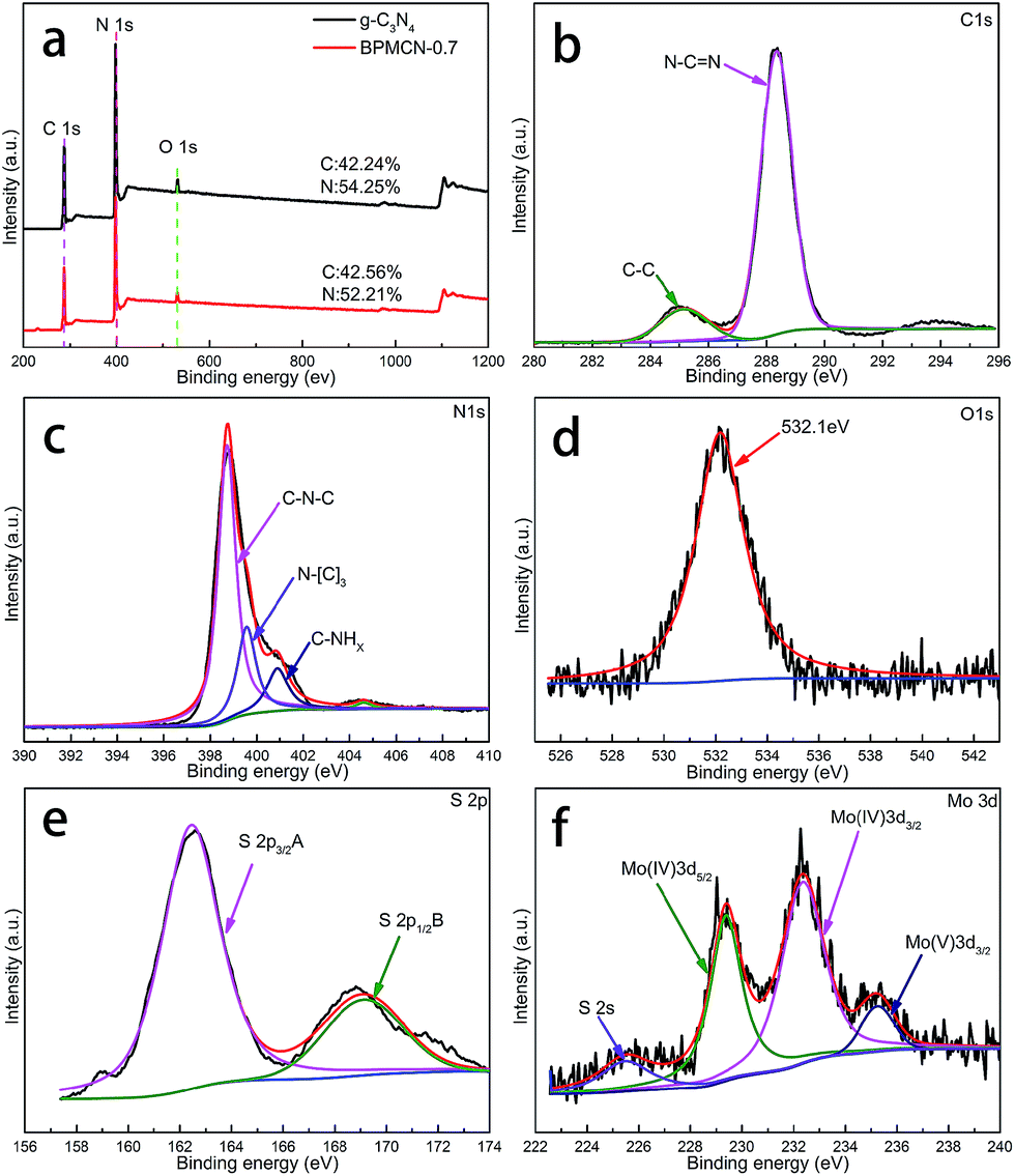 | ||
| Fig. 3 XPS spectra of as-fabricated photocatalysts: (a) survey of g-C3N4 and BPMCN-0.7 and (b) C 1s; (c) N 1s; (d) O 1s; (e) S 2p; (f) Mo 3d of BPMCN-0.7. | ||
In order to verify the detail morphology of the BPMCN heterojunction photocatalysts, TEM has been introduced. As shown in Fig. 4a, compared with pure g-C3N4 (Fig. 4c), the as prepared BPMCN samples with porous morphology exhibit black lamellar feature with transparent parts, indicating it possesses the porous structure. The porous morphology of the BPMCN-0.7 was also investigated via scanning electron microscopy (SEM). As shown in Fig. 4b, the BPMCN-0.7 still maintain porous and irregular 3D morphology, although a great portion of g-C3N4 sheets is stacked. Its morphology is quite different from that of the pure g-C3N4 with a typical layer structure stacked layer by layer (Fig. 4d). To determine the presence of MoS2, EDX elemental mappings are carried out and the results are shown in Fig. 5. Elemental mappings reveal that the BPMCN-0.7 mainly contains five elements (C, N, O, S and Mo), which is coincident with the results of XPS (Fig. 3).
 | ||
| Fig. 4 (a) Typical TEM images and (b) SEM images of BPMCN-0.7, (c) TEM images and (d) SEM images of g-C3N4. | ||
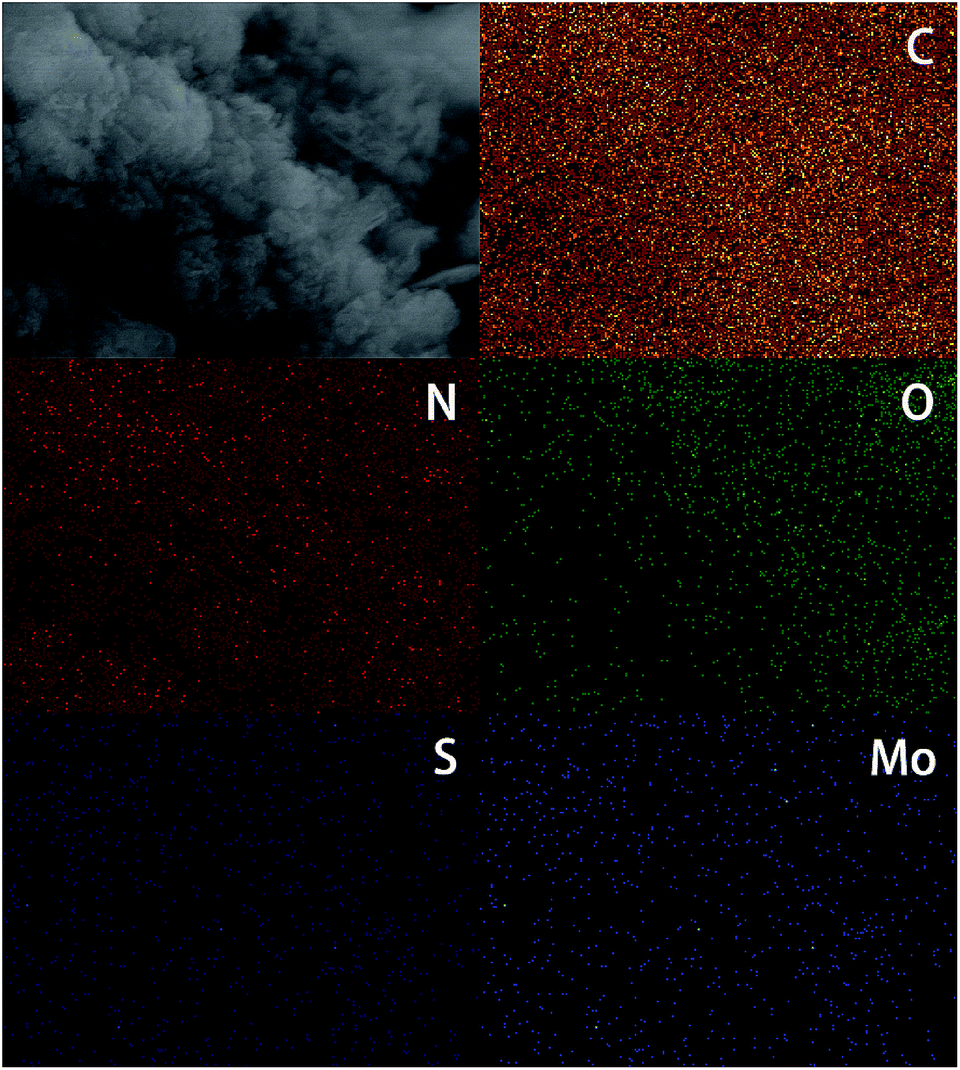 | ||
| Fig. 5 Elemental mapping pattern of BPMCN-0.7. | ||
Fig S3 and S4† display the nitrogen adsorption–desorption isotherms and Barrett–Joyner–Halenda (BJH) pore-size distribution curves of the g-C3N4 and BPMCN samples. It is obvious that the nitrogen adsorption–desorption isotherms (Fig. S3†) for pure g-C3N4 and MoS2/g-C3N4 heterojunction catalysts belong to type IV, which suggests the presence of mesopores. The surface areas and pore volumes (Table S1†) of BPMCN-0.7 (31.92 m2 g−1 and 0.19 cm3 g−1) are significantly higher than those of other BPMCN samples and g-C3N4 (4.48 m2 g−1 and 0.025 cm3 g−1). The pore size distribution of the samples further confirms the formation of mesopores. Mesopores and macropores can be observed in the all sample. The mesopores can be ascribed to the pores formed between the layers, whereas the macropores are the pores on the surface of the layers, as observed in the TEM and SEM image (Fig. 4). The BPMCN-0.7 displays the biggest surface area and pore volume, which is consistent with the results of photocatalytic activity. Therefore, the higher surface area would contribute to the higher photocatalytic activity of the BPMCN-0.7.
To test whether the introduction of MoS2 could improve the photocatalytic efficiency of g-C3N4 in the presence of TEOA, we investigated the g-C3N4 and BPMCN samples as heterogeneous photocatalysts for water splitting to produce hydrogen under visible light (>400 nm). Meanwhile, we studied the influence of the MoS2 amount in the BPMCN samples on the photocatalytic activity under the same conditions. As shown in Fig. 6a and c, the photocatalytic H2 evolution rate of pure g-C3N4 is only 267 μmol g−1 h−1. After the impregnation of MoS2, all the BPMCN photocatalysts show enhanced H2 evolution activity than pure g-C3N4. With the content of MoS2 increase, the amount of H2 first increases and then decreases. The sample with optimal photocatalytic H2 evolution rate is BPMCN-0.7 with H2 evolution of 1640 μmol g−1 h−1, exhibiting about 6-fold increment compared to pure g-C3N4, which is consistent with the result of BET. Without the addition of TEOA, no H2 was detected in the visible light irradiation, mainly due to the high recombination rate of electron–hole pair and the low sensitivity of the detector, which shows that TEOA can separate electron–hole pairs and boost the efficiency of hydrogen production through water splitting. Recently, a report is related to the explored MoS2/g-C3N4 heterostructure for H2 production, its hightest H2 evolution rate reaches 23.1 μmol h−1 (100 mg photocatalyst, λ > 400 nm).37 However, our work indicates H2 production rate of 32.8 μmol h−1 only need 20 mg photocatalyst, which exhibits that our work possesses a potential in the field of photocatalytic water splitting for H2 production. Furthermore, the stability of BPMCN-0.7 was tested by using the same condition for photocatalytic H2 production repeatedly five times under visible-light irradiation (Fig. 6b and d). No obvious deactivation of the catalytic activity is observed for BPMCN-0.7 upon circulation duration, indicating the high stability of the BPMCN photocatalysts during photocatalytic H2 production.
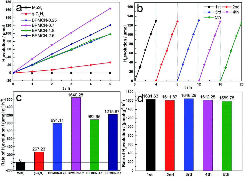 | ||
| Fig. 6 Photocatalytic activity of the photocatalysts (0.020 g) under visible light (a) and (c) H2 evolution rates of the MoS2, g-C3N4 and BPMCN samples in an aqueous solution (90 ml) containing TEOA (10 mL) as the sacrificial agent; (b) and (d) recycling test of BPMCN-0.7 (0.020 g). | ||
Of course, two methods can be applied to the fields of improving the photocatalytic activity. The first one is to extend the absorption edge. The second is to improve the separation efficiency of photogenerated charge. To confirm the reasons for enhanced activity of the samples, we conducted UV-vis diffuse reflectance spectra and the band gap values calculated by plots of (F(R)E)1/2 versus photo energy. As shown in Fig. 7a, the characteristic absorption edge of g-C3N4 is at approximately 455 nm, originating from its intrinsic band gap of 2.72 eV, which has limited visible light absorption ability for itself.13 After introduction of MoS2, the band gap of BPMCN-0.7 is only about 2.33 eV, corresponding to the absorption edge of 532 nm. The absorption edge is transferred from 455 nm to 532 nm.
 | ||
| Fig. 7 (a) The plot of (F(R)E)1/2 versus energy (E) for the band gap energy of g-C3N4 and BPMCN-0.7 samples; (b) PL spectra, (c) electrochemical impedance spectroscopy and (d) transient photocurrent response for the MoS2, g-C3N4 and BPMCN-0.7 samples. | ||
Photoluminescence (PL), caused by the recombination of charge carriers, could also provide a measurement method for the efficiency of the charge carrier trapping, transfer and separation in the samples. As shown in Fig. 7b, the PL intensity for BPMCN-0.7 decreases significantly compared to g-C3N4. In general, a decrease in the PL intensity indicates a suppressed electron–hole pair recombination, which makes BPMCN-0.7 generate more photoelectrons and holes to participate in the photocatalytic reaction. This may be because the heterojunction formed at the interior and interface between g-C3N4 and MoS2 with a high rate of carrier mobility can restrain the recombination of photogenerated charge effectively and accelerate charge transport.
The photogenerated charge separation and electron transfer performance of the BPMCN system were also studied using electrochemical impedance spectroscopy (EIS) and photocurrent responses. The Nyquist plots of g-C3N4 and BPMCN-0.7 are performed to investigate the effect of MoS2 doping. Generally, a smaller arc size reflects smaller charge transfer resistance on the electrode surface. As shown in Fig. 7c, the arc radius on the EIS plots of BPMCN-0.7 is smaller than that of g-C3N4 under visible light, suggesting that the separation and transfer efficiency of photogenerated electron and hole pairs is greatly increased through an interfacial interaction between g-C3N4 and MoS2.
Fig. 7d shows the photocurrent responses via four on–off cycles for bulk the g-C3N4, MoS2 and BPMCN-0.7 materials cast on indium tin oxide glasses. The photocurrents of the BPMCN-0.7 sample were fast and uniform with high reproducibility under visible light irradiation, indicating stable electrodes and a relative reversible photoresponse. It is clear that the BPMCN-0.7 has a higher photocurrent density than that of bulk g-C3N4, which can be ascribed to the existence of heterojunction between MoS2 and g-C3N4, where photogenerated electrons and holes could be efficiently separated in space and the photogenerated carrier recombination will be reduced. As a result, the BPMCN-0.7 sample show enhanced photocurrent. The improved transfer efficiency of charge carriers could lead to the enhanced photocatalytic activity of BPMCN photocatalysts.
Since photoluminescence spectra, electrochemical impedance spectroscopy and photocurrent response are regarded as valid evidences of photogenerated charge separation, these phenomena indicate the improvement of the separation efficiency of photogenerated charge. We consider that the morphology characteristics of material with the porous structure and MoS2/g-C3N4 heterojunction cause the enhanced photocatalytic H2 evolution. For the BPMCN, its porous structure with a greater specific surface area and pore volume is richer than the pure g-C3N4, which may lead to multiple reflections of incident light within the porous channel of the BPMCN and more MoS2/g-C3N4 heterojunction exposed on the surface of the porous channel. It improves the utilization rate of visible light and further expands the visible absorption edge. Meanwhile, the existence of heterojunction between MoS2 with g-C3N4 in the interior and surface can more effectively prevent recombination of photogenerated electrons and holes.
According to UV-vis diffuse reflection spectra and VBXPS (Fig. 7a and S5†), the bottom conduction band and top valence band potentials of g-C3N4 and BPMCN-0.7 are calculated to be −0.62, +2.1, −0.52 and +1.8 V in Fig. 8. In addition, the valence and condition band of MoS2 are consistent with the reported work owing to the similar synthesis strategy.33 The MoS2, as a semiconductor, can form heterojunction with g-C3N4.34,37 I-type heterojunction, which is that the bottom conduction band and top valence band potentials of the MoS2 locate in the forbidden band of the g-C3N4, is observed in MoS2/g-C3N4 samples. The photocatalytic hydrogen evolution mechanism of BPMCN under visible light illumination is showed in Fig. 8. At first, the electrons in the valence band (VB) of g-C3N4 were excited to its conduction band (CB) under irradiation, forming the electron–hole pairs. Then, the photoexcited electrons would transfer from g-C3N4 to MoS2 and Pt and the separated electrons on the surface of MoS2 and Pt would combine with absorbed H+ to produce H2. TEOA, as a sacrificial agent of h+, was introduced into the reaction system. With the decrease of h+, the balance moves to the direction which can produce holes and electrons. The mentioned factor would produce a large amount of electrons and improve the separation efficiency of photogenerated electron–hole pairs, resulting in the improvement of photocatalytic H2 production efficiency.
 | ||
| Fig. 8 Photocatalytic H2 production mechanism for BPMCN. | ||
4. Conclusions
In summary, a new kind of composite photocatalyst of porous MoS2/g-C3N4 heterojunction has been successfully prepared via a novel method called bulk doping strategy. The photocatalytic hydrogen evolution experiments indicate that the MoS2 can efficiently promote the separation of photogenerated charge carriers in g-C3N4, extend light response range, and greatly enhance photocatalytic performance in hydrogen production by water splitting under visible light irradiation. The optimum photocatalytic H2 evolution rate on BPMCN-0.7 reaches 1640 μmol g−1 h−1, which is enhanced by 6 times compared to the bulk g-C3N4. Besides, the BPMCN-0.7 also shows excellent recyclability and chemical stability. This work demonstrates that MoS2 can be a promising semiconductor for developing high efficiency photocatalyst with potential applications in hydrogen production and solar energy utilization.Conflicts of interest
There are no conflicts to declare.Acknowledgements
The work was supported by the National Natural Science Foundation of China (grant No. 21267020).Notes and references
- G. Zhang, G. Li and X. Wang, ChemCatChem, 2015, 7, 2864–2870 CrossRef CAS.
- Q. Liang, Z. Li, Z.-H. Huang, F. Kang and Q.-H. Yang, Adv. Funct. Mater., 2015, 25, 6885–6892 CrossRef CAS.
- D. J. Martin, K. Qiu, S. A. Shevlin, A. D. Handoko, X. Chen, Z. Guo and J. Tang, Angew. Chem., Int. Ed., 2014, 53, 9240–9245 CrossRef CAS PubMed.
- Y. S. Jun, J. Park, S. U. Lee, A. Thomas, W. H. Hong and G. D. Stucky, Angew. Chem., 2013, 52, 11083–11087 CrossRef CAS PubMed.
- S. Cao and J. Yu, J. Phys. Chem. Lett., 2014, 5, 2101–2107 CrossRef CAS PubMed.
- Z. Zhao, Y. Sun and F. Dong, Nanoscale, 2015, 7, 15–37 RSC.
- F. Fresno, R. Portela, S. Suárez and J. M. Coronado, J. Mater. Chem. A, 2014, 2, 2863–2884 CAS.
- Q. Li, N. Zhang, Y. Yang, G. Wang and D. H. L. Ng, Langmuir, 2014, 30, 8965–8972 CrossRef CAS PubMed.
- D. Zheng, G. Zhang, Y. Hou and X. Wang, Appl. Catal., A, 2016, 521, 2–8 CrossRef CAS.
- X. Lu, Y. Jin, X. Zhang, G. Xu, D. Wang, J. Lv, Z. Zheng and Y. Wu, Dalton Trans., 2016, 45, 15406–15414 RSC.
- W. Li, C. Feng, S. Dai, J. Yue, F. Hua and H. Hou, Appl. Catal., B, 2015, 168–169, 465–471 CrossRef CAS.
- D. Chen, Z. Wang, D. Yue, G. Yang, T. Ren and H. Ding, J. Nanosci. Nanotechnol., 2016, 16, 471–479 CrossRef CAS PubMed.
- J. Qin, J. Huo, P. Zhang, J. Zeng, T. Wang and H. Zeng, Nanoscale, 2016, 8, 2249–2259 RSC.
- Z. Chen, S. Pronkin, T. P. Fellinger, K. Kailasam, G. Vile, D. Albani, F. Krumeich, R. Leary, J. Barnard, J. M. Thomas, J. Perez-Ramirez, M. Antonietti and D. Dontsova, ACS Nano, 2016, 10, 3166–3175 CrossRef CAS PubMed.
- J. Deng, H. Li, S. Wang, D. Ding, M. Chen, C. Liu, Z. Tian, K. S. Novoselov, C. Ma, D. Deng and X. Bao, Nat. Commun., 2017, 8, 14430 CrossRef CAS PubMed.
- S. Zhang, B. V. R. Chowdari, Z. Wen, J. Jin and J. Yang, ACS Nano, 2015, 9, 12464–12472 CrossRef CAS PubMed.
- X. Cao, C. Tan, X. Zhang, W. Zhao and H. Zhang, Adv. Mater., 2016, 28, 6167–6196 CrossRef CAS PubMed.
- X. Zhang, Z. Lai, C. Tan and H. Zhang, Angew. Chem., 2016, 55, 8816–8838 CrossRef CAS PubMed.
- S. S. Chou, B. Kaehr, J. Kim, B. M. Foley, M. De, P. E. Hopkins, J. Huang, C. J. Brinker and V. P. Dravid, Angew. Chem., Int. Ed., 2013, 52, 4160–4164 CrossRef CAS PubMed.
- X. Zhang, Z. Lai, C. Tan and H. Zhang, Angew. Chem., Int. Ed., 2016, 55, 8816–8838 CrossRef CAS PubMed.
- Z.-F. Huang, J. Song, L. Pan, Z. Wang, X. Zhang, J.-J. Zou, W. Mi, X. Zhang and L. Wang, Nano Energy, 2015, 12, 646–656 CrossRef CAS.
- Z. Wang, W. Guan, Y. Sun, F. Dong, Y. Zhou and W.-K. Ho, Nanoscale, 2015, 7, 2471–2479 RSC.
- H. Tong, S. Ouyang, Y. Bi, N. Umezawa, M. Oshikiri and J. Ye, Adv. Mater., 2012, 24, 229–251 CrossRef CAS PubMed.
- F.-Y. Su and W.-D. Zhang, Chem.–Asian J., 2017, 12, 515–523 CrossRef CAS PubMed.
- L. Shi, K. Chang, H. Zhang, X. Hai, L. Yang, T. Wang and J. Ye, Small, 2016, 12, 4431–4439 CrossRef CAS PubMed.
- X. Chen, H. Li, Y. Wu, H. Wu, L. Wu, P. Tan, J. Pan and X. Xiong, J. Colloid Interface Sci., 2016, 476, 132–143 CrossRef CAS PubMed.
- S. P. Adhikari, G. P. Awasthi, H. J. Kim, C. H. Park and C. S. Kim, Langmuir, 2016, 32, 6163–6175 CrossRef CAS PubMed.
- X. Pan, X. Chen and Z. Yi, ACS Appl. Mater. Interfaces, 2016, 8, 10104–10108 CAS.
- H.-J. Li, B.-W. Sun, L. Sui, D.-J. Qian and M. Chen, Phys. Chem. Chem. Phys., 2015, 17, 3309–3315 RSC.
- Y. Cao, Q. Li and W. Wang, RSC Adv., 2017, 7, 6131–6139 RSC.
- H. Yu, P. Xiao, P. Wang and J. Yu, Appl. Catal., B, 2016, 193, 217–225 CrossRef CAS.
- J. Yan, Z. Chen, H. Ji, Z. Liu, X. Wang, Y. Xu, X. She, L. Huang, L. Xu, H. Xu and H. Li, Chemistry, 2016, 22, 4764–4773 CrossRef CAS PubMed.
- Y. Hou, A. B. Laursen, J. Zhang, G. Zhang, Y. Zhu, X. Wang, S. Dahl and I. Chorkendorff, Angew. Chem., 2013, 52, 3621–3625 CrossRef CAS PubMed.
- S. A. Ansari and M. H. Cho, Sci. Rep., 2017, 7, 43055, DOI:10.1038/srep43055.
- W.-J. Ong, L.-L. Tan, S.-P. Chai, S.-T. Yong and A. R. Mohamed, Nano Energy, 2015, 13, 757–770 CrossRef CAS.
- X. Ding, W. Ho, J. Shang and L. Zhang, Appl. Catal., B, 2016, 182, 316–325 CrossRef CAS.
- Y. Tian, L. Ge, K. Wang and Y. Chai, Mater. Charact., 2014, 87, 70–73 CrossRef CAS.
Footnote |
| † Electronic supplementary information (ESI) available. See DOI: 10.1039/c7ra06774g |
| This journal is © The Royal Society of Chemistry 2017 |