 Open Access Article
Creative Commons Attribution 3.0 Unported Licence
Synthesis, characterization, and properties of nickel–cobalt layered double hydroxide nanostructures
Chunxian Xinga,
Farayi Musharavatib,
Hui Li a,
Erfan Zalezhad*a,
Oscar K. S. Huic,
Sungchul Bae*d and
Bum-Yean Choe
aDepartment of Mechanical Convergence Engineering, Hanyang University, 222 Wangsimni-ro, Seongdong-gu, Seoul, 04763, Korea. E-mail: e.zalnezhad@gmail.com
bMechanical and Industrial Engineering Department, College of Engineering, Qatar University, 2713 Doha, Qatar
cSchool of Mathematics, Faculty of Science, University of East Anglia, Norwich NR4 7TJ, UK
dDepartment of Architectural Engineering, Hanyang University, Seoul, 04763, Korea. E-mail: sbae@hanyang.ac.kr
eDepartment of Architectural Engineering, University of Seoul, Seoul, Korea
First published on 9th August 2017
Abstract
Nickel–cobalt layered double hydroxides (Ni–Co-LDH) have recently been examined for their potential as battery-type hybrid supercapacitors made from metal hydroxide electrode materials, due to their unique spatial structure, excellent electrochemical activity, and good electrical conductivity. However, the main disadvantage restricting the application of Ni–Co-LDHs is their low electronic conductivity, which results in low capacitance. To address this problem, we used different concentrations of ammonium fluoride to control the Ni–Co-LDH surface morphology and direct growth on Ni foam (NF). We created Ni–Co-LDH composite electrode materials with different morphologies that showed large surface areas, high conductivity, and high electrochemical performance. Results showed that the samples prepared with ammonium fluoride additive had a higher specific capacity of about 1445 F g−1 at a current density of 2 A g−1, a good specific capacitance rate of about 59.5% from 2 A g−1 to 40 A g−1, and good capacity retention of up to 99% when the current density was enhanced to 30 A g−1, suggesting promise for future applications.
1. Introduction
Electrochemical capacitors (ECs), often called supercapacitors (SCs), are components that store electrical energy at the interface between a solid electrode and electrolyte. ECs have been used in energy storage for nearly a century. However, their low energy density has limited their use in low-power applications, such as components for short-term memory backup supplies or analog circuits.1–4 With the development of manufacturing technology, many low resistance and high surface area electrode materials have resulted from the ability to store more energy as electric charge. Supercapacitors are attracting increasing research attention because they rapidly provide higher energy densities than conventional dielectric capacitors and higher power densities than secondary batteries.5–10 The electrodes are commonly made from carbon-based active electrode materials,11 transition metal oxides (RuO2,12 Co3O4,13 NiCo2O4 (ref. 14)) and hydroxides (Co(OH)2 (ref. 15) and Ni(OH)2 (ref. 16)), and conducting redox polymers.17Metallic layered double hydroxides (LDHs) are promising positive electrode materials for SCs. LDHs have the general formula [M1−x2+Mx3+(OH)2]x+[An−x/n·mH2O]x−, where M2+ and M3+ represent bivalent (e.g., Ni, Mg, Cu, Zn) and trivalent metal ions (e.g. Co, Al, Fe, Mn), x = 0.2–0.33, An− is the charge-balancing anion, and mH2O represents the interlayer water molecules. Ni foam-supported LDHs have attracted attention as potential catalysts for water splitting, batteries, and other applications. They can also be used as binder-free electrodes in high-performance supercapacitors, which has stimulated growing interest in the application of ECs.18–21 In particular, Ni–Co-LDHs are considered good candidates with high specific capacities. The developed Ni–Co-LDH nanostructures can deliver high specific capacitance because of their reasonable mesoporous pore-size distribution, high specific surface area, and the synergistic effects of Ni/Co and multiple Co valance states (Co2+, Co3+). However, the semiconductor nature of Ni–Co-LDHs, along with other transition metal-based LDHs or hydroxides as typical battery-type materials, has exacerbated their poor rate capability. Their kinetics, particularly at high rates, are limited by diffusion-controlled and phase-change processes, which lead to structural instability and a reduced capacity.22 Consequently, research has been carried out to enhance their performance by mixing with carbon materials to fabricate nanosized architectures to activate more surface reaction sites or develop improved conductivity.23,24 One such attempt used Ni foam (NF), which is highly conductive, light, and cost-effective. By facilitating maximum use of the active materials, the severe agglomeration of LDH was reduced. Three-dimensional porous NF provides more canals that enable electrolyte ions to quickly penetrate the active LDH electrode materials, and the direct contact of LDH on NF avoids the use of polymer binder/conductive additives compared with common slurry-coating technology. Through electrochemical tests, this method has been shown to produce ultrahigh capacitance, good rate capability at high current density, and low resistance. Some LDH electrode materials have been produced by adding ammonium fluoride (NH4F) to improve the electrochemical properties. However, the effect of NH4F on the electrochemical properties has yet to be studied in depth.
In this study, a simple and effective method for adding NH4F was used to prepare high-performance Ni–Co-LDH electrodes by hydrothermal synthesis, using Ni foam as the substrate to enable the growth of vertical Ni–Co-LDH nanostructures. Different amounts of NH4F were used to prepare Ni–Co-LDHs with different nanostructures, and their physical characterization and electrochemical performance were discussed.
2. Experimental details
2.1. Ni-Foam-based Ni–Co-LDH electrode preparation
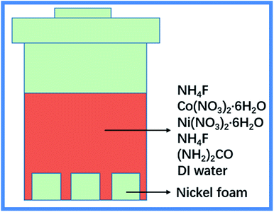
All chemicals used in this study were of analytical grade and used without further purification. Ni foam (10 mm × 10 mm × 0.1 mm) was cleaned consecutively with acetone, absolute ethanol, 1 N HCl, and distilled water, and then stirred with ultrasonication for 15 min to remove the possible surface oxide layer. Co(NO3)2·6H2O (0.5 mmol) was mixed with Ni(NO3)2·6H2O (1 mmol) in deionized (DI) water (50 mL) and then stirred with ultrasonication for 30 min. Next, urea (6 mmol) was mixed with different amounts of NH4F (0 mmol, 0.75 mmol, 1.5 mmol, 2.25 mmol, 3 mmol, and 4.5 mmol) at 10 min intervals with constant stirring. These samples were marked as A, B, C, D, E, and F, respectively. The cleaned Ni foam and urea/NH4F solution were transferred to a 100 mL Teflon stainless steel autoclave and treated at 100 °C for 8 h to allow Ni–Co-LDH growth. Once the autoclave had cooled to ambient temperature, the product was collected, rinsed with ethanol and deionized water to remove surface ions and adsorbed solvents, and dried at 60 °C for 12 h. Fig. 1 shows a schematic illustration of the fabrication process for the Ni–Co-LDH nanostructures.2.2. Characterization
Ni–Co-LDH specimens were characterized by X-ray diffraction (XRD, Bruker D8 Advance X-ray) using Cu Kα radiation (λ = 0.15406 nm) at 40 kV and 30 mA from 5° to 80° at 5° min−1. The structures and morphologies of the specimens were characterized using field emission scanning electron microscopy (FESEM, LEO-1530, Zeiss) with an applied voltage of 5 kV.The electrochemical properties of the samples were examined under a three-electrode system using a 6 M KOH aqueous solution as the electrolyte at ambient temperature. Prior to tests, the Ni–Co-LDH–NF selected as the working electrode was soaked in 6 M KOH solution and degassed under vacuum for 5 h. A saturated calomel electrode (SCE) and platinum foil were used as the reference and counter electrodes, respectively. Cyclic voltammetry (CV), galvanostatic charge/discharge measurements, and electrochemical impedance spectroscopy (EIS) were performed using a ZIVE SP2 electrochemical working station. EIS measurements were performed over a frequency range of 100 kHz to 0.01 Hz at the open circuit potential with an AC perturbation of 5 mV. The specific capacity of each specimen was determined from the galvanostatic charge/discharge curves using the following equation:
3. Results and discussion
3.1. Synthesis and characterization
The metal hydroxide nanostructures were prepared by hydrothermal synthesis from an aqueous solution of a metal–fluoro complex, [MFn]m−n, which was gradually hydrolyzed by adding water. The Ni–Co-LDH–NF electrodes were also prepared by hydrothermal synthesis. In this process, the following reactions occurred:25| Co(NH2)2 + H2O → 2NH3 + Co2 | (1) |
| Co2 + H2O → Co32− + 2H+ | (2) |
| NH3 + H2O → NH4+ + OH− | (3) |
| M2+ + xF− → MFx(x−2)− | (4) |
| Ni2+ + xF− → [NiFx](x−2)− | (5) |
| [NiFx](x−2)− + nH2O → [NiFx−n(OH)n](x−2)− + nHF | (6) |
| 2Ni2+ + Co2+ + 4OH− + Co32− + H2O → Ni2Co(Co3)(OH)4·H2O | (7) |
When the temperature was increased from room temperature to 100 °C, the urea initially decomposed (1)–(3). Reactions (4) and (5) then afforded fresh Ni parent solution [NiFx](x−2)−. Then, in the presence of water, the reversible hydrolytic reaction of [NiFx](x−2)− and [NiFx−n(OH)n](x−2)− occurred, producing hydrogen fluoride (6). As the reaction progressed, [NiFx−n(OH)n](x−2)− was slowly hydrolyzed to [Ni(OH)x](x−2)−, forming an α/β-Ni(OH)2 mixed structure. During this time, the added Co3+ ions were inserted into the crystal lattice. The trivalent cobalt ion displaced nickel ions in the nickel hydroxide laminates. Finally, Ni–Co-LDHs were formed on the substrate surface (7).
Fig. 2 shows the diffraction patterns of powder samples of Ni–Co-LDHs with different amounts of NH4F (0–4.5 mmol). The XRD pattern of Ni–Co-LDH exhibited (006), (003), (015), (012), (107), (018), (1010), (0111), (113), and (116) reflections, representing the characteristic hydrotalcite-type structure (JCPDS 33-0426). The diffraction peaks become higher after adding NH4F, showing that Ni–Co-LDH had better crystallinity with increasing NH4F concentration. Ni(II) hydroxide has two well-characterized polymorphs, α and β. The α-structure consists of Ni(OH)2 layers with intercalated anions or water. The β-form adopts a hexagonal close-packed structure of Ni2+ and OH− ions. Nickel hydroxide was present in the α-form in Ni–Co-LDH. A new β-Ni(OH)2 phase (JCPDS 14-0117) emerged with increasing NH4F concentration (Fig. 2B–F).26–28
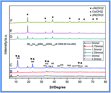 | ||
| Fig. 2 XRD pattern of Ni–Co-LDHs with different amounts of NH4F: (A) 0 mmol, (B) 0.75 mmol, (C) 1.5 mmol, (D) 2.25 mmol, (E) 3 mmol, and (F) 4.5 mmol. | ||
With added NH4F, the XRD pattern exhibited new reflections at 19.258°, 33.064°, 38.541°, 52.100°, 59.052°, 60.240°, 72.737°, and 73.169°. With increasing NH4F concentration, the α-Ni(OH)2 peaks decreased, while the β-Ni(OH)2 peaks increased, indicating that more β-Ni(OH)2 was produced. This change in nickel hydroxide crystal structure was caused by the introduction of fluorine ions from NH4F, which resulted in a metal–fluoro complex, [NiFn]m−n, that was gradually hydrolyzed to β-Ni(OH)2 by water.
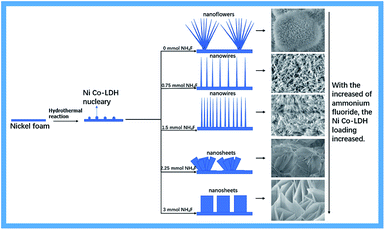
Fig. 3 shows a possible formation mechanism for Ni–Co-LDHs supported on Ni foam. NH4F played an essential role in activating the substrates, resulting in the formation of Ni–Co-LDHs. NH4F is largely associated with adhesion between the substrate and arrays. Without NH4F participation, only needle-like nanowires and nanoflower arrays of Ni foam were observed. As the amount of NH4F increased, new β-Ni(OH)2 was produced. The unique α-Ni(OH)2/β-Ni(OH)2 hybrid structure altered the original Ni–Co-LDH nanostructures. Meanwhile, fluorine ions produced nickel foam with a high binding energy to the Ni–Co-LDH, resulting in the close growth of the nanostructures on nickel foam and increased loading.
Fig. 4 shows SEM images of the Ni–Co-LDH–NF composites containing different amounts of NH4F (0–4.5 mmol). Fig. 4a and a′ (the latter showing a higher degree of magnification) show a large number of acicular nanosphere structures with short needles. Fig. 4b and b′ show a structure consisting of numerous nanowires and a few nanoflowers with slender nanowires. Fig. 4c and c′ show numerous nanowire structures. As the amount of NH4F increased, a Ni–Co-LDH nanosheet array morphology was observed, as shown in Fig. 4. Ni–Co-LDH directly deposited on the NF substrate resulted in a dense distribution of nanoflakes, which diminished the specific surface area. Fluorine ions are strongly electronegative, leading to an increased metal ion binding energy, which results in LDH growth occurring closer to the nickel foam surface. Under the influence of fluorine ions and the α/β-Ni(OH)2 mixed structure, the Ni–Co-LDHs formed unique nanostructures.
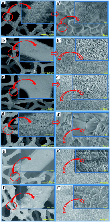 | ||
| Fig. 4 SEM images of Ni–Co-LDH–NF composites containing different amounts of NH4F: (a) 0 mmol, (b) 0.75 mmol, (c) 1.5 mmol, (d) 2.25 mmol, (e) 3 mmol, and (f) 4.5 mmol. | ||
The nanowire structures were perpendicular to the nickel foam surface. When the nanowires were the same size as the nanostructure, the nanowires had a larger surface area and higher efficiency in electrochemical reactions. In battery-type supercapacitors, the surface area directly influences the electrochemical properties in surface oxidation/reduction reactions. The surface affects the wetting ability of materials and electrolyte entry into the material. A larger surface area can facilitate the diffusion of active species and electron transport and, therefore, may further broaden their applications in electrochemical supercapacitors.29 However, when further increasing the NH4F concentration, numerous nanosheets were grown on the nickel foam. Reduced surface areas decrease the electrochemical performance.30
3.2. Electrochemical characterization
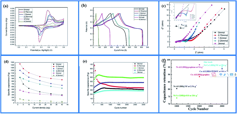
For applications in energy storage, Ni–Co-LDH nanowire arrays on Ni foam were used in supercapacitor electrodes to determine their potentiality. Fig. 5a shows CV curves of the as-prepared Ni–Co-LDHs in 6 M KOH solution at a scan rate of 5 mV s−1. All Ni–Co-LDH–NF electrodes produced CV curves at different sweep rates that showed typical battery-type characteristics, with two highly reversible redox peaks within a potential window of 0 to 0.6 V. This was due to the faradaic redox reactions between M–O–OH and M–OH (M represents Ni or Co ions). The main reaction process was described as follows:19| Ni(OH)2 + OH− ↔ NiOOH + H2O + e− |
| CO(OH)2 + OH− ↔ CoOOH + H2O + e− |
| CoOOH + OH− ↔ CoO2 + e− |
The Ni–Co-LDH–NF electrodes had the highest peak currents, as shown in Fig. 5a, demonstrating improved charge transfer in the specimen. The reduction and oxidation peak currents had good symmetry, and their response to current was roughly the same, showing good electrochemical reversibility. Comparing the electrode CV curves clearly showed that, with added NH4F (0.75 mmol or 1.5 mmol), the electrode reduction and oxidation peaks were higher, and the oxidation reduction peak slope was increased, demonstrating that the larger surface area of the nanowires afforded a faster electron transfer rate. Adding different amounts of NH4F (0 mmol, 3 mmol, and 4.5 mmol) caused the electrode reduction and oxidation peaks to become less sharp. NH4F at 0.75 mmol in the electrode produced faster charge transfer efficiency and better oxidation–reduction reversibility.
Ni–Co-LDH–NF charge/discharge curves within the potential range 0–0.55 V at different current densities are shown in Fig. 5b. When the charge/discharge current was 2 A g−1, the corresponding values of specific capacitance were 945, 1445, 1206, 951, 476, and 151 F g−1 for 0, 0.75, 1.5, 2.25, 3, and 4.5 mmol of NH4F, respectively. The results showed that using the appropriate amount of NH4F improved the electrochemical properties, while larger amounts reduced the specific capacitance of the Ni–Co-LDHs.
The electrode electrochemical impedance spectroscopy (EIS) curves of the samples are shown in Fig. 5c. The curve of the sample electrode had a high frequency area (half arc), intermediate frequency area (transition section), and a low frequency area. The electrode resistance was small because the resistance of the nanosheet was lower than that of the nanowire. This was due to the nanowire having a larger specific surface area, which made the substance more active and guided dielectric full contact in the electrode reaction.31 Electron and proton diffusion occur easily, but a large surface can decrease the apparent density and increase contact resistance.32 For the high-frequency semicircle, the diameter signified electrode and electrolytic liquid surface charge transfer resistance.33 A smaller semicircle diameter corresponded to smaller electrochemical impedance. As the amount of NH4F was increased (0–3 mmol), the semicircle diameter became smaller. Fluorine ions created nickel foam with a high binding energy to Ni–Co-LDHs, causing the charge from the active material to rapidly transfer to the nickel foam. The low-frequency area line signifies ion diffusion resistance inside the material, with larger straight slopes representing performance closer to ideal capacitance.33
The poor performance of the Ni–Co-LDH–NF materials at high current densities was due to their poor intrinsic conducting nature. Fig. 5d shows the electrode specific capacity at different current densities. When the current density was increased to 40 A g−1, the electrode specific capacity retention rates were 59.5%, 54.22%, 57.73%, and 58.12% with NH4F contents of 0.75, 1.5, 2.25, and 3 mmol, respectively. Without adding NH4F to the electrode, the retention rate was only 31.5%. The high performance ratios were mainly attributed to the introduction of NH4F. This characteristic was very important for supercapacitors under different current densities, even high current density, as it can result in better capacitance performance.34
Cycle life is an important factor in electrochemical performance. The electrochemical stability of the Ni–Co-LDH–NF samples at 30 A g−1 over 3000 cycles is shown in Fig. 5e. The capacitive retention rates were 88%, 40%, 90%, 99%, and 97% for NH4F contents of 0, 0.75, 1.5, 2.25, and 3 mmol, respectively. At 0.75 mmol of NH4F, the capacitive retention rate was very low. This was due to the single nanowire being slender, and α-Ni(OH)2 having more molecular defects, which led to poor cycle stability. Continuous charge and discharge tests destroyed its nanostructure and reduced its electrochemical properties. However, the increasing β-Ni(OH)2 content obtained with increasing NH4F content resulted in Ni–Co-LDH–NF samples with better capacity retention. These findings showed that Ni–Co-LDH–NF exhibited excellent cycling stability when adding more than 90% NH4F and increasing the current density to 30 A g−1. Cai et al.35 previously fabricated Ni–Co-LDHs decorated on rGO with a cycle stability of 74% for 1000 cycles at a current density of 20 A g−1. Furthermore, Zhang et al.36 synthesized Co–Al-LDH/graphene with a cycle stability of 89% for 2000 cycles at a current density of 10 A g−1. Compared with these previously reported systems, Ni–Co-LDH–NF samples exhibited excellent cycle stability at higher current densities (Fig. 5f).
4. Conclusion
In this study, Ni–Co-LDHs containing different amounts of NH4F were grown on Ni foam as high-performance supercapacitor electrodes using the hydrothermal method. By adding NH4F, the prepared Ni–Co-LDH–NF electrodes attained high specific capacities of about 1445 F g−1 and high cycling stabilities of more than 90% after 3000 cycles of activation at 30 A g−1. Good specific capacitance of about 59.5% was also achieved at 2–40 A g−1, which was higher than that of most previously reported Ni–Co-LDH-based materials. These findings demonstrate that adding NH4F to Ni–Co-LDH–NF electrodes has great potential for applications in energy storage devices.Acknowledgements
This work was performed at the Thin Film Coating Laboratory, Engineering Center, Hanyang University. The work was supported financially by Hanyang University, Young Faculty Forum, and by a grant (16TBIP-C111710-01) from the Technology Innovation Program funded by the Ministry of Land, Infrastructure and Transport of the Korean Government.References
- R. F. Service, Science, 2006, 313, 902 CrossRef CAS PubMed.
- P. Simon and Y. Gogotsi, Nat. Mater., 2008, 7, 845–854 CrossRef CAS PubMed.
- J. R. Miller and P. Simon, Science, 2008, 321, 651–652 CrossRef CAS PubMed.
- P. Simon, Y. Gogotsi and B. Dunn, Science, 2014, 343, 1210–1211 CrossRef CAS PubMed.
- J. Yang, P. X. Xiong, C. Zheng, H. Y. Qiu and M. D. Wei, J Mater Chem A, 2014, 2, 16640–16644 CAS.
- F. X. Ma, L. Yu, C. Y. Xu and X. W. Lou, Energy Environ. Sci., 2016, 9, 862–866 CAS.
- J. Chang, M. Jin, F. Yao, T. H. Kim, V. T. Le, H. Yue, F. Gunes, B. Li, A. Ghosh, S. Xie and Y. H. Lee, Adv. Funct. Mater., 2013, 23, 5074–5083 CrossRef CAS.
- L. L. Peng, X. Peng, B. R. Liu, C. Z. Wu, Y. Xie and G. H. Yu, Nano Lett., 2013, 13, 2151–2157 CrossRef CAS PubMed.
- J. W. Lee, J. M. Ko and J. D. Kim, J. Phys. Chem. C, 2011, 115, 19445–19454 CAS.
- J. C. Huang, T. Lei, X. P. Wei, X. W. Liu, T. Liu, D. X. Cao, J. L. Yin and G. L. Wang, J. Power Sources, 2013, 232, 370–375 CrossRef CAS.
- J. K. Ou, Y. Z. Zhang, L. Chen, Q. Zhao, Y. Meng, Y. Guo and D. Xiao, J Mater Chem A, 2015, 3, 6534–6541 CAS.
- V. Subramanian, S. C. Hall, P. H. Smith and B. Rambabu, Solid State Ionics, 2004, 175, 511–515 CrossRef CAS.
- C. Z. Yuan, L. Yang, L. R. Hou, L. F. Shen, F. Zhang, D. K. Li and X. G. Zhang, J. Mater. Chem., 2011, 21, 18183–18185 RSC.
- G. Q. Zhang, H. B. Wu, H. E. Hoster, M. B. Chan-Park and X. W. Lou, Energy Environ. Sci., 2012, 5, 9453–9456 CAS.
- W. J. Zhou, X. H. Cao, Z. Y. Zeng, W. H. Shi, Y. Y. Zhu, Q. Y. Yan, H. Liu, J. Y. Wang and H. Zhang, Energy Environ. Sci., 2013, 6, 2216–2221 CAS.
- F. Cao, G. X. Pan, P. S. Tang and H. F. Chen, J. Power Sources, 2012, 216, 395–399 CrossRef CAS.
- A. M. P. Hussain, D. Saikia, A. Kumar, F. Singh and D. K. Avasthi, Indian J. Phys., 2005, 79, 783–787 CAS.
- G. P. Wang, L. Zhang and J. J. Zhang, Chem. Soc. Rev., 2012, 41, 797–828 RSC.
- Y. Liu, N. Y. Wang, Z. W. Cao and J. Caro, J Mater Chem A, 2014, 2, 1235–1238 CAS.
- W. Liu, J. Bao, M. Guan, Y. Zhao, J. Lian, J. Qiu, L. Xu, Y. Huang, J. Qian and H. Li, Dalton Trans., 2017, 46(26), 8372–8376 RSC.
- X. Zhu, C. Tang, H.-F. Wang, B.-Q. Li, Q. Zhang, C. Li, C. Yang and F. Wei, J. Mater. Chem. A, 2016, 4, 7245–7250 CAS.
- H. Chen, L. F. Hu, M. Chen, Y. Yan and L. M. Wu, Adv. Funct. Mater., 2014, 24, 934–942 CrossRef CAS.
- C. Yu, J. Yang, C. T. Zhao, X. M. Fan, G. Wang and J. S. Qiu, Nanoscale, 2014, 6, 3097–3104 RSC.
- H. Jiang, T. Zhao, C. Z. Li and J. Ma, J. Mater. Chem., 2011, 21, 3818–3823 RSC.
- L. J. Zhang, J. Wang, J. J. Zhu, X. G. Zhang, K. S. Hui and K. N. Hui, J Mater Chem A, 2013, 1, 9046–9053 CAS.
- Y. Ren and L. A. Gao, J. Am. Ceram. Soc., 2010, 93, 3560–3564 CrossRef CAS.
- J. T. Li, W. Zhao, F. Q. Huang, A. Manivannan and N. Q. Wu, Nanoscale, 2011, 3, 5103–5109 RSC.
- Y. Wang, S. L. Gai, C. X. Li, F. He, M. L. Zhang, Y. D. Yan and P. P. Yang, Electrochim. Acta, 2013, 90, 673–681 CrossRef CAS.
- J. Yan, Z. Fan, T. Wei, W. Qian, M. Zhang and F. Wei, Carbon, 2010, 48, 3825–3833 CrossRef CAS.
- T. Hiraoka, A. Izadi-Najafabadi, T. Yamada, D. N. Futaba, S. Yasuda, O. Tanaike, H. Hatori, M. Yumura, S. Iijima and K. Hata, Adv. Funct. Mater., 2010, 20, 422–428 CrossRef CAS.
- X. S. Yin, C. H. Tang, L. Y. Zhang, Z. G. Yu and H. Gong, Sci. Rep., 2016, 6, 21566 CrossRef CAS PubMed.
- C. Zheng, X. F. Zhou, H. L. Cao, G. H. Wang and Z. P. Liu, J. Power Sources, 2014, 258, 290–296 CrossRef CAS.
- L. H. Su, X. G. Zhang, C. H. Mi and Y. Liu, J. Power Sources, 2008, 179, 388–394 CrossRef CAS.
- A. Malak-Polaczyk, C. Vix-Guterl and E. Frackowiak, Energy Fuels, 2010, 24, 3346–3351 CrossRef CAS.
- X. Cai, X. Shen, L. Ma, Z. Ji, C. Xu and A. Yuan, Chem. Eng. J., 2015, 268, 251–259 CrossRef CAS.
- L. Zhang, X. Zhang, L. Shen, B. Gao, L. Hao, X. Lu, F. Zhang, B. Ding and C. Yuan, J. Power Sources, 2012, 199, 395–401 CrossRef CAS.
| This journal is © The Royal Society of Chemistry 2017 |

