 Open Access Article
Design of a multifunctional vanadium pentoxide/polymer biocomposite for implant-coating applications†
N. Anicic *ab,
M. Vukomanovica and
D. Suvorova
aAdvanced Materials Department, Jozef Stefan Institute, Jamova Cesta 39, SI-1000 Ljubljana, Slovenia. E-mail: nemanja.anicic@ijs.si
bJozef Stefan International Postgraduate School, Jamova Cesta 39, SI-1000 Ljubljana, Slovenia
First published on 7th August 2017
Abstract
In this study we designed a multifunctional implant coating by exploiting the properties of vanadium pentoxide (V2O5), i.e., the antibacterial activity via myeloperoxidase-like catalytic activity and the bioactivity of low concentrations of vanadate ions (dissolved form of V2O5) via the insulin-mimicking effect. To achieve this, the dissolution control of the V2O5 and the sustained release of the vanadate ions had to be achieved by processing the appropriate carrier system for the V2O5. Thus, we evaluated the ability of different polymeric carriers and the V2O5 particle morphology to modulate in vitro the stability of the prepared V2O5/polymeric coatings. For the control of the V2O5 dissolution it was crucial to control the diffusion of the particles from the polymeric matrix to the surrounding medium and to prevent extensive swelling of the polymer matrix. We highlighted the correlation between the strength of the interactions at the V2O5/polymer interface and the composite's stability under simulated physiological conditions. The optimum outcome was obtained for a nanowires-V2O5/PLGA composite coating that delivered vanadates sustainably, while at the same time preventing the colonization of S. epidermidis (NCIMB 8853) on its surface and ensuring the absence of any harmful effects on the red blood cells.
Introduction
If effectively stabilized, vanadium pentoxide (V2O5) is a potential multifunctional material that exhibits antibacterial and bioactive properties. This material could be used for implant coatings, as it could successfully target the “race for the implant surface” between cells and bacteria.1 Recent studies have highlighted the ability of nanostructured V2O5 to mimic the myeloperoxidase activity,2,3 which is effectively utilized for the processing of an anti-biofouling ship-hull coating.3 Myeloperoxidase is an enzyme that is present in human neutrophils. Its role is to eliminate bacteria via catalysis of the hydrogen-peroxide-to-hypochlorite transformation in the presence of chloride ions.4 In this context there is a possibility to exploit the unique property of V2O5 to design antimicrobial coatings for applications in medicine, which has so far not been discussed.The use of V2O5 in medicine is limited by its relatively high solubility in aqueous media (>1 g l−1), while the so-formed, high concentrations of vanadate ions are toxic to human cells.5,6 However, in vitro studies also showed their bi-phasic nature, as these ions are able to stimulate the cell proliferations of various types of mammalian cells at low concentrations (up to 10 μM).7,8 They exhibit an insulin-mimicking action via the inhibition of tyrosine phosphatase.9 In vivo studies of rats proved that orally administrated vanadates stimulated the orientation of the fibroblasts in parallel arrays early in the tissue-repair process, i.e., vanadate ions can accelerate tissue repair.10–12 Further studies confirmed that vanadates improved the bone-formation rate, the mechanical strength and the mineralization,13 while the pro-oxidant potential of vanadates was not revealed in erythrocytes.14 These studies confirmed the bioactive potential of the vanadate ions when they are properly delivered.
V2O5 could be used as a source of vanadate ions if its solubility is strictly controlled. To do this, V2O5 has to be integrated inside a composite. Polymers are widely used as carriers for the controlled administration of molecules, macromolecular species or nanoparticles.15–17 Some of them, including poly (lactic-co-glycolic) acid (PLGA), polylactic acid (PLA), polystyrene (PS) and chitosan, are already established as very effective drug-delivery systems. These polymers differ in their properties (including their hydrophilic/hydrophobic character, the rate and extent of their biodegradability, surface chemistry, etc.), which can be effectively used to design a drug-delivery system in line with the requirements of the final application, i.e., to retain the catalytic activity of the V2O5 and keep the level of eluted vanadates below 10 μM. The controlled release of active substances from these systems is a complex process that is influenced by the physico-chemical properties of the polymer matrix, the release medium and the active compound (V2O5). In general, the diffusion of the active material, the polymeric matrix swelling and the matrix degradation are considered to be the main driving forces for the elution of the drug from the matrix.18 One of the common outcomes is a burst release of the active species from the matrix during the first few hours of exposure.16,19 Such an outcome has to be avoided for V2O5/polymer biocomposites, which makes the stabilization of V2O5 within the polymer matrix critical during the initial stage of the exposure to aqueous media.
We were processing an innovative multifunctional V2O5/polymer composite system in the form of a coating that is capable of retaining the antibacterial properties of V2O5 and, at the same time, providing strict control over the vanadate-release kinetics during the initial stage of its exposure to the medium. For this purpose, we evaluated and explained the impact of the V2O5 particle morphology and the interface interactions on the in vitro performance of V2O5/polymer composite coatings.
Materials and methods
Synthesis and processing methods
![[thin space (1/6-em)]](https://www.rsc.org/images/entities/char_2009.gif) :
:![[thin space (1/6-em)]](https://www.rsc.org/images/entities/char_2009.gif) H2O2 was 1
H2O2 was 1![[thin space (1/6-em)]](https://www.rsc.org/images/entities/char_2009.gif) :
:![[thin space (1/6-em)]](https://www.rsc.org/images/entities/char_2009.gif) 10. The as-prepared solution was transferred to a Teflon-lined autoclave, sealed and held at 200 °C for 24 h. At the end of the process the precipitate was collected, washed with deionized water and lyophilized.
10. The as-prepared solution was transferred to a Teflon-lined autoclave, sealed and held at 200 °C for 24 h. At the end of the process the precipitate was collected, washed with deionized water and lyophilized.![[thin space (1/6-em)]](https://www.rsc.org/images/entities/char_2009.gif) :
:![[thin space (1/6-em)]](https://www.rsc.org/images/entities/char_2009.gif) 50, Resomer RG 505, Evonik Industries) in dichloromethane (40 mg ml−1) was mixed with 1.5 ml of a suspension of V2O5 (varied from 0.08 to 4 mg ml−1) in dichloromethane and left under the hood overnight to allow for the solvent's evaporation. The embedding of V2O5 NWs in a PLA (Resomer LR 704 S, Evonik industries) or PS (99% purity, Sigma Aldrich) matrix involved the same procedure as with PLGA. Chitosan (purity 99%, Sigma Aldrich) was dissolved in 1% acetic acid solution instead of dichloromethane during the V2O5/chitosan composite coating's preparation procedure.
50, Resomer RG 505, Evonik Industries) in dichloromethane (40 mg ml−1) was mixed with 1.5 ml of a suspension of V2O5 (varied from 0.08 to 4 mg ml−1) in dichloromethane and left under the hood overnight to allow for the solvent's evaporation. The embedding of V2O5 NWs in a PLA (Resomer LR 704 S, Evonik industries) or PS (99% purity, Sigma Aldrich) matrix involved the same procedure as with PLGA. Chitosan (purity 99%, Sigma Aldrich) was dissolved in 1% acetic acid solution instead of dichloromethane during the V2O5/chitosan composite coating's preparation procedure.Methods of physico-chemical characterization
![[thin space (1/6-em)]](https://www.rsc.org/images/entities/char_2009.gif) :
:![[thin space (1/6-em)]](https://www.rsc.org/images/entities/char_2009.gif) 1. The ATR-IR spectra were obtained in the range 650 to 4000 cm−1.
1. The ATR-IR spectra were obtained in the range 650 to 4000 cm−1.In vitro vanadate elution kinetics
![[thin space (1/6-em)]](https://www.rsc.org/images/entities/char_2009.gif) 500 rpm for 15 min to obtain clear, particle-free supernatants that were removed and stored for a later quantification of the vanadate ions. The measurements were performed in triplicate.
500 rpm for 15 min to obtain clear, particle-free supernatants that were removed and stored for a later quantification of the vanadate ions. The measurements were performed in triplicate.Antibacterial activity studies
Hemocompatibility studies
Before use the red blood cells were diluted in the HEPES buffer (Sigma Aldrich, 99.5%) to a final concentration of 5 × 10⁷ RBC per ml. The RBCs were incubated with the prepared materials for 24 h. After the exposure, the cells were centrifuged at 1000g for 10 minutes. The supernatants were evaluated for haemoglobin content by the means of UV/Vis absorption at 415 nm (Synergy H1, Biotec).
Results
Morphology and structure of V2O5 powders
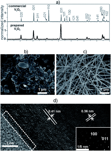
Before embedding inside the composites, we made a structural characterization of both the commercial and the hydrothermally prepared V2O5 powders. In both cases the XRD patterns matched the orthorhombic crystal structure of the V2O5 (JCPDS card 85-0601) and exhibited the same phase composition (Fig. 1a). In comparison to the commercial V2O5, the diffraction pattern of the hydrothermally prepared V2O5 exhibited only (0kl) peaks, i.e., the diffraction peaks representing the (110), (101), (111), (130), (121), (141) and (102) crystallographic directions were not observed (Fig. 1a). These findings indicate that the hydrothermally prepared V2O5 crystals displayed a preferential orientation, which was not the case for the crystals of the commercial powder.The difference in the orientation of the hydrothermally prepared and commercial V2O5 particles was further studied using SEM analyses. The average size of the commercial V2O5 crystals was 230 ± 25 nm. These crystals had an irregular shape, a low aspect ratio and did not show any preferential orientation (Fig. 1b), so they were denoted as 0D V2O5 sub-microparticles (V2O5 MPs). In contrast, the hydrothermally prepared V2O5 crystals exhibited a significant anisotropy and a high aspect ratio, characteristic for a 1D nanowire morphology and were denoted as V2O5 NWs (Fig. 1c). The average width of the particles was 40 ± 10 nm, while the average length was 26 ± 15 μm. Each individual nanowire was a single crystal, as point diffraction was observed in the SAED pattern (Fig. 1d). These crystals possessed a highly ordered crystal structure and a very thin amorphous layer (less than 0.5 nm) at the surface (Fig. 1d, white dashed triangle). The interplanar distances in both the SAED and the HR-TEM were complementary and confirmed the preferential growth of the nanowires along the [100] direction.
The difference in the morphology caused a significant difference in the BET surface areas of the commercial and hydrothermally prepared V2O5. The commercial V2O5 MPs had a specific surface area of 4.5 m2 g−1, while the specific surface area of the prepared V2O5 NWs was 30.7 m2 g−1. The anisotropy and the larger specific surface area of the 1D nanowires were expected to allow easier processing and obtaining a higher level of homogeneity for the V2O5/polymer composites.
The role of particle morphology on the solubility control of V2O5
The solubility assay showed that the initial rate of dissolution was higher for the V2O5 NWs than for the commercial V2O5 MPs in the PBS medium (Fig. 2a). The vanadates' concentration in the V2O5 nanowire suspension was almost four times higher than the corresponding concentration in the commercial V2O5 suspension after 6 h of exposure. The levels of the vanadates were equalized in both suspensions after a long exposure (t = 8 days) to the PBS medium. Thus, there is a difference in the kinetics of dissolution, which is faster for the 1D nanoparticles than for the 0D sub-micron particles. There was no difference observed in the thermodynamics of the dissolution. The nanoparticles dissolved faster than the microparticles6 due to the larger surface available for an interaction with the solvent (30.7 vs. 4.5 m2 g−1 in our study).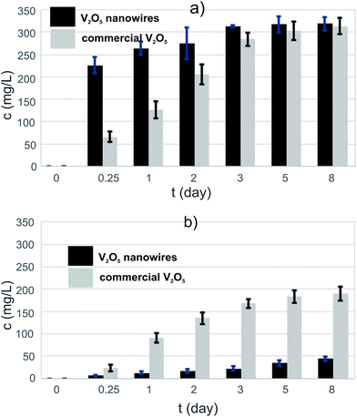 | ||
| Fig. 2 The increase of vanadate concentration after exposure to PBS medium of (a) pure V2O5s and (b) V2O5/PLGA composites. | ||
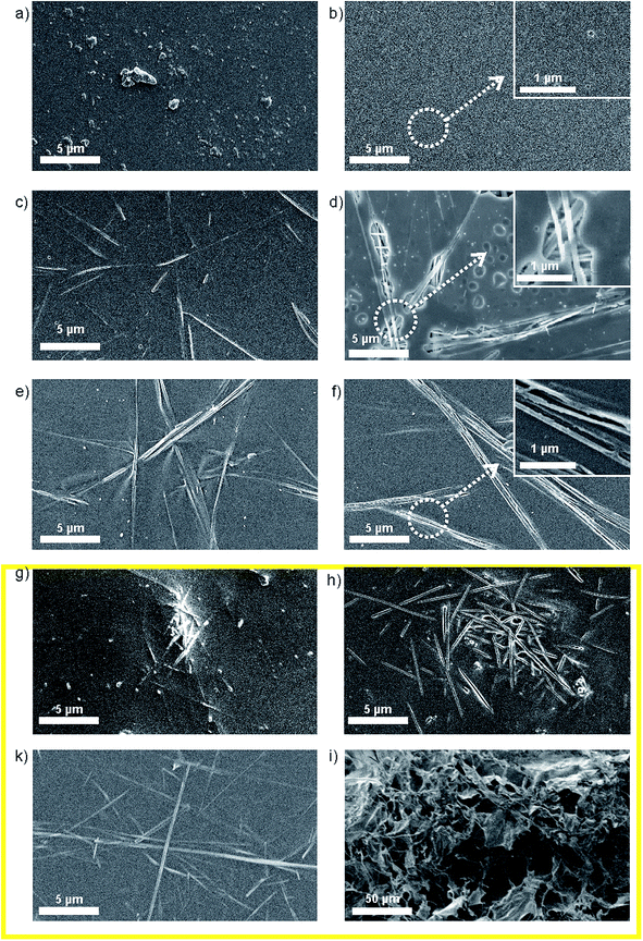
The level of the eluted vanadates in both V2O5 suspensions was two orders of magnitude above the bioactivity concentration range,7 which confirmed the need for an efficient vanadate-delivery system. Thus, the ability of the PLGA to reduce the dissolution of V2O5 in the PBS was tested for both powders. The PLGA matrix was able to reduce the vanadate elution to the PBS, i.e., to control the solubility of the V2O5 (Fig. 3b). In contrast to the pure powders, the vanadate elution from a composite containing V2O5 nanowires was lower than from one containing commercial V2O5 (Fig. 2b), i.e., the vanadate level after t = 8 days of exposure to the PBS medium was more than four times lower. The 0D sub-micron particles were not observed on the surface of the V2O5/PLGA composite after 4 days of exposure to the PBS (Fig. 3b). We observed just 200 nm-sized holes at the PLGA surface, because hydrolytic degradation of the PLGA had begun. Similarly, the formation of up to 1 μm-sized pores was also observed on the surface of the V2O5 nanowires/PLGA composite (Fig. 3d). However, the nanowires were still attached to the surface. They were partly exposed to the PBS medium, as just parts of their length were completely covered by the PLGA.
The SEM study of the V2O5/PLGA surface indicated that the 0D sub-micron particles diffuse from the PLGA surface into the PBS, while the diffusion of the nanowires is hindered. As a consequence, the elution of the vanadate ions from the V2O5-nanowires/PLGA composite is slower than from the commercial V2O5/PLGA composite. In both cases, the coating thickness was not changed after 1 day of exposure to the PBS, i.e. the body of the polymer matrix was still stable (Fig. S2b and d†). We concluded that the 1D nanoparticle morphology of the V2O5 allows more efficient control of the vanadate elution compared to the 0D sub-micron particle morphology.
Surface of the prepared V2O5 NWs/polymer composites
To analyse the ability of different polymers to control the solubility of V2O5 nanowires, we incorporated them inside various polymeric carriers. Before the exposure to the PBS medium the surface morphology of the prepared composites was investigated (Fig. 3). The reference composite based on the PLGA matrix exhibited embedded 0D sub-micron V2O5 particles on the surface (Fig. 3a). The extent of the V2O5 particles' coverage with the polymer matrix varied. Some particles were almost completely covered with the PLGA matrix, while others were just slightly immersed inside the matrix. A similar distribution of V2O5 MPs was observed at the surface of V2O5 MPs/PLA and V2O5 MPs/chitosan composites (Fig. S1a and c†). In comparison to the 0D V2O5 MPs, we observed that the coverage of the 1D V2O5 NWs by the PLGA matrix was better (Fig. 3c), as just small portions of the individual nanowires were exposed to the environment. The nanowires were dispersed along the matrix and lay almost in plane with the surface. We observed a similar distribution of nanowires at the surface of the V2O5 NWs/PLA and V2O5 NWs/chitosan (Fig. 3e and k). We observed a similar distribution of nanowires at the surface of the V2O5 NWs/PLA and V2O5 NWs/chitosan (Fig. 3e and k). In contrast, at the surface of V2O5 NWs/PS composites bunches of agglomerated nanowires were identified (Fig. 3g).The thickness of the analysed composites was between 10 and 15 μm (Fig. S1c, e and g†). They did not contain bubbles as a consequence of solvent evaporation (Fig. S2c, e and g†).
Behaviour of the coatings made from different V2O5 NWs/polymer composites under in vitro conditions.
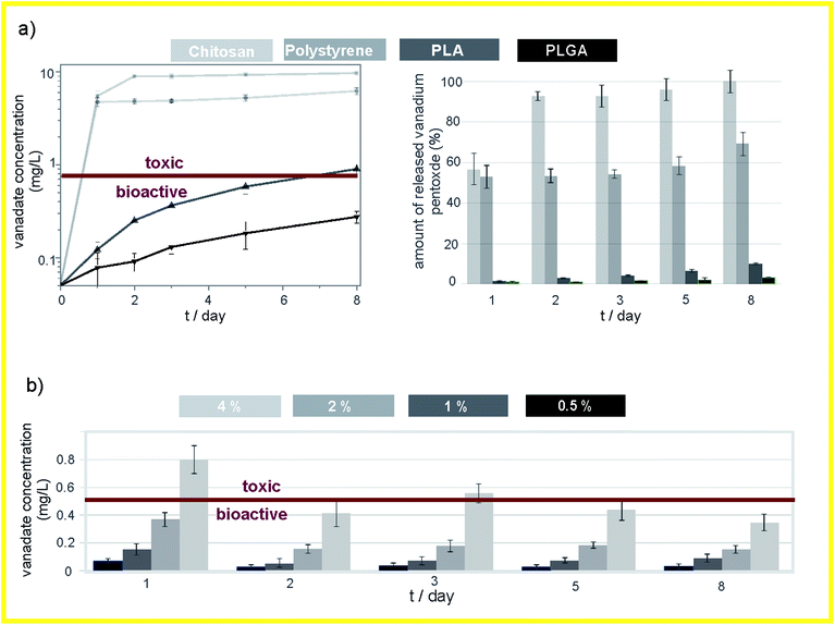
The release of vanadates from the V2O5 NWs/PLGA does not show any significant initial burst effect and the release of vanadates is constant over time (Fig. 4a). The concentration of the released vanadates is within the bioactive concentration range (below the mark, Fig. 4a). Similarly, the elution kinetics of the vanadates from the V2O5 NWs/PLA (Fig. 4a) showed no initial burst effect, but the final concentration was no longer within the bioactive concentration range and the amount of the released vanadates after 8 days of exposure to the PBS was almost four times higher when compared to the V2O5 NWs/PLGA composite (Fig. 4a). The morphology of the V2O5 NWs/PLA surface revealed holes in the shape of the nanowires after 1 day long exposure to the PBS, which implies that the PLA matrix is not efficient for the retention of the nanowires (Fig. 3f). In addition, the PLA matrix was also not able to retain the V2O5 MPs (Fig. S1b†). In the case of the V2O5/PS composite, almost 55% of the incorporated V2O5 was released after 1 day of exposure to the PBS, while in the next 7 days only 10% of the material was released, i.e., the initial burst effect was observed (Fig. 4a). The overall concentration of the vanadates is an order of magnitude above the bioactive range (Fig. 4a). The morphology of the V2O5 NWs/PS surface exhibited holes in the shape of the nanowires after the exposure to the PBS, proving the burst release of whole nanowire agglomerates (Fig. 3h). In all three cases (V2O5 NWs/PLGA, V2O5 NWs/PLA and V2O5 NWs/PS) the coating thickness was not changed after 1 day of exposure to the PBS, i.e. body of polymer matrix was still stable (Fig. S2d, f and h†).The V2O5 NWs/chitosan composite exhibited the lowest ability to control the elution kinetics of the vanadates. Namely, more than 90% of the incorporated nanowires were dissolved from the V2O5 NWs/chitosan composite after 2 days of exposure to the PBS (Fig. 4a). In contrast to the other V2O5/polymer systems, the coating collapse was observed in the SEM micrograph of the V2O5 NWs/chitosan surface, which could be related to the swelling of the matrix and the up-take of water from the medium (Fig. 3h). As a result, the thickness of the coating increased from 10 μM to more than 200 μM (Fig. S2h†). The collapse of the chitosan matrix was also observed after the exposure of the V2O5 the MPs/chitosan to the PBS medium (Fig. S1d†).
The daily elution study of the vanadate release from the V2O5 NWs/PLGA composites confirmed the absence of any initial burst effect (Fig. 4c). The maximum allowed amount of embedded V2O5 NWs inside the PLGA matrix is 2%, as higher loadings resulted in a vanadate release outside the bioactive concentration range (Fig. 4c).
The study showed that the PLGA, the PLA and the PS differ in their ability to control the dissolution of the nanowires. The polarity of these polymers (based on contact-angle measurements) decreases from PLGA over to PLA to PS,23–25 same as their ability to control vanadate release from the corresponding V2O5 NWs/polymer composites. Therefore, we anticipated that the polarity of the polymer matrix is related to the strength of the interface interactions at the V2O5/polymer interface. In contrast, the chitosan is a highly hydrophilic polymer with a high swelling rate, i.e., the ability to absorb a large amount of water.26 We showed that swelling of the matrix has a negative influence on the control of vanadate elution from the V2O5 NWs/chitosan composite due to the coating's collapse. Thus, in the following section dedicated to interphase interactions, the V2O5 NWs/chitosan composite was not evaluated.
Study of the interface interactions in the V2O5 NWs/polymer composites
The nature of the interphase interactions inside the V2O5 NWs/polymer composites was studied by the means of FT-IR technique. The ATR-IR spectrum of the V2O5 nanowires (Fig. 5a) consists of two absorption maxima. The sharp one, at 1012 cm−1, is assigned to the vibration modes of the V![[double bond, length as m-dash]](https://www.rsc.org/images/entities/char_e001.gif) OA bond. This oxygen is bonded to a single vanadium atom. The broad band at 858 cm−1 corresponds to the vibrations of the V–OB–V structure. The OB is bonded to two vanadium atoms and is a bridging atom between two corner-sharing octahedra.27,28 The ATR-IR spectrum of PS (Fig. 5a) showed the presence of its characteristic bands. The absorption maxima in the range from 1400 to 1600 cm−1 correspond to the C
OA bond. This oxygen is bonded to a single vanadium atom. The broad band at 858 cm−1 corresponds to the vibrations of the V–OB–V structure. The OB is bonded to two vanadium atoms and is a bridging atom between two corner-sharing octahedra.27,28 The ATR-IR spectrum of PS (Fig. 5a) showed the presence of its characteristic bands. The absorption maxima in the range from 1400 to 1600 cm−1 correspond to the C![[double bond, length as m-dash]](https://www.rsc.org/images/entities/char_e001.gif) C stretching vibration of the styrene aromatic rings. The bands in the range from 1000 to 1275 cm−1 belong to the in-plane C–H bending, while the absorption maxima in the range from 600 to 900 cm−1 belong to the out-of-plane C–H bending.29 The ATR-FTIR spectrum of the V2O5/PS composite is a combination of the individual V2O5 and PS IR spectra (Fig. 5a). In the regions where individual bands are overlapping, a convolution of peaks is observed (e.g., the band of PS at 854 cm−1 convolutes with the V2O5 band at 858 cm−1, as indicated).
C stretching vibration of the styrene aromatic rings. The bands in the range from 1000 to 1275 cm−1 belong to the in-plane C–H bending, while the absorption maxima in the range from 600 to 900 cm−1 belong to the out-of-plane C–H bending.29 The ATR-FTIR spectrum of the V2O5/PS composite is a combination of the individual V2O5 and PS IR spectra (Fig. 5a). In the regions where individual bands are overlapping, a convolution of peaks is observed (e.g., the band of PS at 854 cm−1 convolutes with the V2O5 band at 858 cm−1, as indicated).
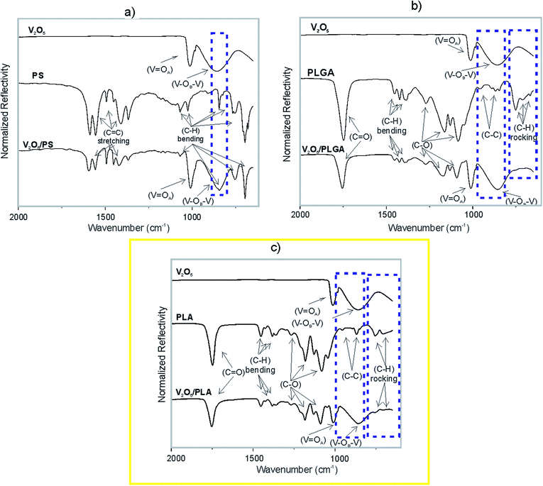 | ||
| Fig. 5 ATR-IR spectrum of (a) V2O5 NWs, PS and V2O5 NWs/PS; (b)V2O5 NWs, PLGA and V2O5 NWs/PLGA; (c) V2O5 NWs, PLA and V2O5 NWs/PLA. | ||
The ATR-IR spectrum of the PLGA (Fig. 5b) and PLA (Fig. 5c) showed the presence of characteristic bands of polyesters. The absorption bands at 668, 712 and 753 cm−1 correspond to the C–H rocking vibrations.30,31 The sharp absorption maximum at 1746 cm−1 is assigned to the vibration of the carbonyl group (C![[double bond, length as m-dash]](https://www.rsc.org/images/entities/char_e001.gif) O).30,31 The bands at 1271, 1162, 1130, 1084 and 1050 cm−1 are assigned to the C–O stretching bond vibration, while the bands at 1452, 1432, 1393, 1384 and 1366 belong to the C–H bending vibrations. Furthermore, the absorption maxima at 956, 922, 891, 868 and 846 cm−1 correspond to the C–C stretching vibrations.30,31 Not all of the vibrational modes of the V2O5 and the PLGA are present in the IR spectrum of the V2O5/PLGA (Fig. 5b). The peaks corresponding to the C–H rocking vibration are not present (indicated by a dashed rectangle). These vibration bands are present in the IR spectra of V2O5 NWs/PLA, but are strongly reduced in intensity (Fig. 5c). It is not clear whether the C–C stretching vibration bands are still present in both, the V2O5 NWs/PLGA and V2O5 NWs/PLA composites as they overlap with the strong V–OB–V band of the V2O5 (indicated by a dashed rectangle).
O).30,31 The bands at 1271, 1162, 1130, 1084 and 1050 cm−1 are assigned to the C–O stretching bond vibration, while the bands at 1452, 1432, 1393, 1384 and 1366 belong to the C–H bending vibrations. Furthermore, the absorption maxima at 956, 922, 891, 868 and 846 cm−1 correspond to the C–C stretching vibrations.30,31 Not all of the vibrational modes of the V2O5 and the PLGA are present in the IR spectrum of the V2O5/PLGA (Fig. 5b). The peaks corresponding to the C–H rocking vibration are not present (indicated by a dashed rectangle). These vibration bands are present in the IR spectra of V2O5 NWs/PLA, but are strongly reduced in intensity (Fig. 5c). It is not clear whether the C–C stretching vibration bands are still present in both, the V2O5 NWs/PLGA and V2O5 NWs/PLA composites as they overlap with the strong V–OB–V band of the V2O5 (indicated by a dashed rectangle).
These results indicate the presence of strong intermolecular interactions at the V2O5 NWs/PLGA interface, as the C–H vibration maxima of the PLGA matrix are overwhelmed. These interphase interactions were also observed within the V2O5 NWs/PLA composite, but are weaker in intensity than within the V2O5 NWs/PLGA, because C–H rocking vibrations were just partially overwhelmed. In contrast, the IR analysis confirmed absence of such interactions within the V2O5/PS composite.
Interaction of V2O5 nanowires and the V2O5/PLGA composite coatings with biological systems
We tested the ability of the V2O5 nanowires to eliminate the bacteria via the catalysis of the hydrogen-peroxide-to-hypochlorite transformation in the presence of Cl−. Planktonic bacteria with 100% viability (according to a BacLight live/dead assay) were the starting point (Fig. 6a). This starting viability of the bacteria was not significantly influenced when the vanadates, the V2O5 nanowires or a combination of H2O2 and Cl− (without V2O5) were added to the phosphate buffer (Fig. 6a). These results indicated that neither the pure form of the V2O5 nor the released vanadates were able to harm the bacteria. However, the joint effect of the V2O5 and the chloride ions reduced the bacteria's viability by 75%. At the same time, the solution where the production of hypochlorite was expected (combined effect of V2O5, Cl− and H2O2) lowered the viability by just 25% (Fig. 6a), due to the increased solubility of the V2O5 in the presence of H2O2.20 In the phosphate buffer containing V2O5 and Cl−, the number of eliminated S. epidermidis (3.3 × 10⁶ CFU ml−1 g−1) is higher than the number of eliminated E. coli (2.2 × 10⁶ CFU ml−1 g−1). Using this test, we confirmed the ability of the V2O5 nanowires to cause the catalytically induced elimination of both the Gram-positive (S. epidermidis) and Gram-negative (E. coli) bacterial strains (Fig. 6b).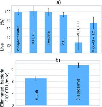 | ||
| Fig. 6 (a) The percentage of live bacteria after 3 h exposure to various media and (b) the number of eliminated bacteria after exposure to phosphate buffer containing V2O5 and chloride ions. | ||
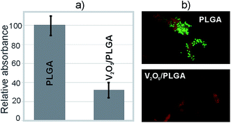
Testing was also performed for the V2O5 NWs/PLGA composite coatings, relating to their ability to prevent bacteria colonization at the surface. After an overnight incubation of the agar plates, on which the solution above the evaluated coatings was smeared after vigorous stirring, no colony growth was observed. This indicated the complete colonization of the S. epidermidis at the surface of the coatings. However, a difference in the number of adsorbed bacteria was observed. The CV assay showed that the amount of colonized bacteria on the surface of the V2O5 NWs/PLGA composite coatings was more than three times lower than at the surface of the PLGA coating (Fig. 7a). The live/dead assay revealed that the majority of the colonized bacteria at the surface of the V2O5 NWs/PLGA composite were dead because the red signal was much stronger than the green signal. In contrast, a significant green signal is observed at the surface of the PLGA, which proved the presence of live bacteria at the surface of the PLGA (Fig. 7b).
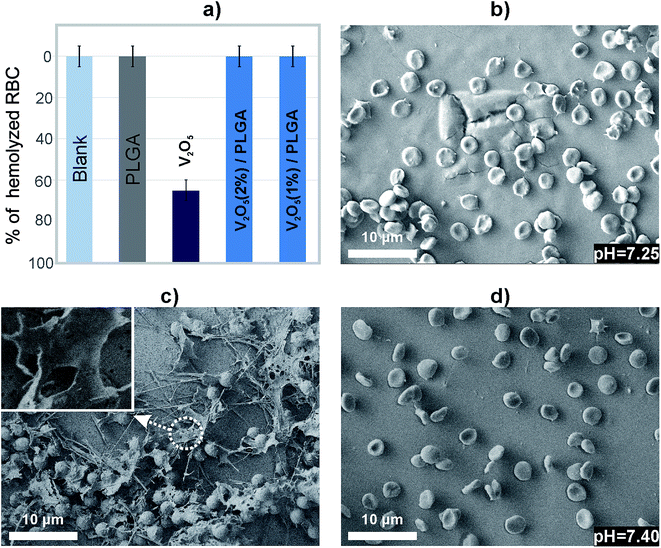
The V2O5 nanowires caused hemolysis of 65% of the RBCs, according to the haemoglobin absorption (Fig. 8a). In contrast, the either PLGA or V2O5 NWs/PLGA composite coatings showed the absence of hemolysis (Fig. 8a). To evaluate the impact of the RBCs/material interactions on the cell morphology, they were observed by means of the SEM. It was reported that normal RBCs exhibit a smooth biconcave structure.32 In the case of PLGA coating, the attached RBCs exhibited irregularities in the shape, but there was no membrane rupture observed (Fig. 8b). As the pH of the solution was reduced, we concluded that degradation of PLGA caused a release of the acid products and impacted on the morphology of the RBCs.
The RBCs at the surface of V2O5 NWs/PLGA composite coating did not exhibited irregularities at the surface, observed in the case of PLGA as well as membrane-damaged cells (Fig. 8d). There was no drop in the pH of the medium, which indicated the ability of V2O5 to modify the degradation of the PLGA.
Discussion
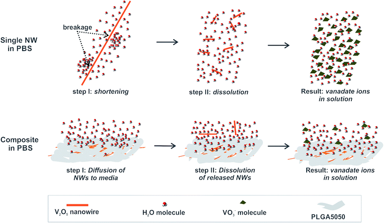
Based on the findings related to the dissolution of free V2O5 nanowires and their solubility after embedding in a PLGA matrix, we propose the following mechanism for control over the V2O5 dissolution provided by the PLGA matrix (illustrated in Fig. 9).When exposed to the PBS medium, a single V2O5 nanowire interacts with the surrounding water molecules, which causes the introduction of a shear stress at the nanowire due to the large aspect ratio. As a consequence, they are first broken and then dissolved. Even though parts of the individual nanowires in the V2O5 NWs/PLGA were exposed (Fig. 3d) to the surrounding water molecules, the stresses induced by the water molecules were transferred along the polymer matrix, resulting in the prevention of the nanowires' breakage and thus their dissolution. However, a small portion of the nanowires diffused out of the matrix and due to the free exposure to water molecules, they eventually dissolved.
Therefore, the success of the V2O5 solubility control from the V2O5/PLGA depends on hindering the particles' diffusion into the PBS in the early stage of the exposure. V2O5 nanowires have a large aspect ratio and are situated almost in-plane with the PLGA surface (Fig. 3c and d). Thus, their diffusion towards the PBS is greatly hindered and a small portion of them are released from the PLGA matrix. This explains the efficient solubility control of the V2O5 nanowires inside the PLGA matrix (Fig. 4b). In contrast, the 0D sub-micron particles of the commercial V2O5 are randomly oriented inside the PLGA matrix and their diffusion from the matrix is not restricted. This explains why the solubility control of the 0D V2O5 in the PLGA matrix is not as efficient as the solubility control of the 1D V2O5.
Apart from the PLGA, the PLA, PS and chitosan were also evaluated for their ability to control the solubility of the V2O5 NWs. PLGA and PLA are synthetic, biocompatible and biodegradable polymers and are among the best defined polymers for applications in drug delivery.25 Polystyrene is inert to mammalian cells and is used as a substrate of microplates for testing the cellular response to various stimuli.33 Chitosan is recognized for its osteoconductive, enhanced wound healing and antibacterial properties, which make it an attractive candidate for use in implant-coating technology.34
The strength of the interaction at the V2O5 NWs/polymer interface impacts on the diffusion of the V2O5 NWs towards the PBS. The PLGA and PLA monomeric units contain polar C–O and C![[double bond, length as m-dash]](https://www.rsc.org/images/entities/char_e001.gif) O bonds. Oxygen is highly electronegative, which induces a positive charge on the neighbouring C atoms. Via the inductive effect, this charge is partially transferred to the remaining C and H atoms, causing the creation of a partial positive charge on these atoms (Fig. S3a and b†). As the IR analysis confirmed, the C–H atoms interact with the surfaces of the vanadium pentoxide nanowires where the oxygen atoms are partially negative (Fig. S3a and b†). Thus, we proposed dipole–dipole interface interactions within both the V2O5 NWs/PLGA and V2O5 NWs/PLA composites (Fig. S3a and b†). The number of C and H atoms is smaller in the PLGA than in the PLA monomeric unit, which causes a higher partial positive charge on the C and H atoms in the PLGA than in the PLA monomeric unit. i.e., the dipole–dipole interactions are stronger within the V2O5 NWs/PLGA than within the V2O5 NWs/PLA composites (Fig. S3a and b†). Because of that, (i) the C–H vibrations bands are overwhelmed in the IR spectra of the V2O5 NWs/PGLA, while greatly reduced (but still present) in the IR spectra of the V2O5 NWs/PLA (Fig. 5b and c) and (ii) these interactions are strong enough to retain the nanowires within the PLGA matrix (Fig. 3d), while not sufficient to retain them within the PLA matrix (Fig. 3f). In contrast to the PLA and PLGA, the PS does not contain polar bonds, i.e., there is no charge separation and induction of a partially positive charge (Fig. S3c†). As a consequence, there are no dipole–dipole interphase interactions within the V2O5 NWs/PS composites involving C–H bonds and nanowires, which is proved by the absence of any effect on the C–H vibration bands in the IR analysis (Fig. 5a).
O bonds. Oxygen is highly electronegative, which induces a positive charge on the neighbouring C atoms. Via the inductive effect, this charge is partially transferred to the remaining C and H atoms, causing the creation of a partial positive charge on these atoms (Fig. S3a and b†). As the IR analysis confirmed, the C–H atoms interact with the surfaces of the vanadium pentoxide nanowires where the oxygen atoms are partially negative (Fig. S3a and b†). Thus, we proposed dipole–dipole interface interactions within both the V2O5 NWs/PLGA and V2O5 NWs/PLA composites (Fig. S3a and b†). The number of C and H atoms is smaller in the PLGA than in the PLA monomeric unit, which causes a higher partial positive charge on the C and H atoms in the PLGA than in the PLA monomeric unit. i.e., the dipole–dipole interactions are stronger within the V2O5 NWs/PLGA than within the V2O5 NWs/PLA composites (Fig. S3a and b†). Because of that, (i) the C–H vibrations bands are overwhelmed in the IR spectra of the V2O5 NWs/PGLA, while greatly reduced (but still present) in the IR spectra of the V2O5 NWs/PLA (Fig. 5b and c) and (ii) these interactions are strong enough to retain the nanowires within the PLGA matrix (Fig. 3d), while not sufficient to retain them within the PLA matrix (Fig. 3f). In contrast to the PLA and PLGA, the PS does not contain polar bonds, i.e., there is no charge separation and induction of a partially positive charge (Fig. S3c†). As a consequence, there are no dipole–dipole interphase interactions within the V2O5 NWs/PS composites involving C–H bonds and nanowires, which is proved by the absence of any effect on the C–H vibration bands in the IR analysis (Fig. 5a).
Apart from the described influence on the surface morphology of the V2O5 NWs/polymer composites after exposure to the PBS and IR spectra, the absence/presence of these interactions plays an important role during the preparation procedure for the composites. In the case of PLGA and PLA, dipole–dipole interphase interactions help stabilize the nanowires in the polymer solution by preventing extensive re-agglomeration (Fig. 3c and e). Without them the nanowires re-agglomerate like in the case of the V2O5 NWs/PS (Fig. 3g). As a result, predominantly individual nanowires were released from the PLA surface, while whole bunches of agglomerated nanowires were released from the PS upon exposure to the PBS, making the initial burst effect more pronounced in the case of the PS (Fig. 4a).
The water-swelling properties of the polymer matrix impacted the diffusion of V2O5 NWs towards the PBS. It compromised the efficacy of the chitosan to control the release of the vanadates from the V2O5 NWs/Chitosan coating.
Regarding the antibacterial potential of V2O5 NWs, we related it completely to its ability to catalyse the transformation of hydrogen peroxide to hypochlorite ions. We proposed a two-stage mechanism. Firstly, the V2O5 NWs produces a small amount of hydrogen peroxide, as previously suggested.35 We have confirmed that this amount is not sufficient to affect the bacteria, as their viability was not reduced. However, in the presence of chloride ions, hydrogen peroxide is transformed to hypochlorite ions, which effectively eliminate the bacteria. The further addition of hydrogen peroxide to the solution containing chloride ions reduced the antibacterial potential of the V2O5. This was a consequence of the accelerated dissolution of V2O5 in the presence of added H2O2, which caused the reduced area for catalysis when compared to the V2O5 in the phosphate buffer containing chloride ions. Although the ROS production is common for metal oxides,36 V2O5 has a unique ability to transform it to more potent hypochlorite ions.
We exploited the antimicrobial potential of V2O5 to protect the PLGA surface. S. epidermidis is a representative strain, as it causes more than 30% of all the implant-related bacterial infections.37 The bacteria concentration used in the evaluations of the V2O5 NWs/PLGA antibacterial potential was two orders of magnitude higher than proposed by ISO 22196:2007(E), because the use of lower concentrations led to experiments with large standard deviations. Taking this into account, the V2O5 was successful in preventing bacteria adhesion at the surface of the PLGA, as the number of colonized bacteria was 70% lower. The application of the BacLight assay might be problematic for biofilms because the precise number of colonized bacteria was unknown, which might lead to the overexpression of the red colour.38 Although it was not possible to determine the associated percentages of live and dead bacteria at the surface, we were still able to state, based on the ratios between the red and green colours, that the viability of the attached S. epidermidis at the surface of the V2O5 NWs/PLGA was reduced when compared to the PLGA surface. Thus, the V2O5 exhibited antibacterial protection of the PLGA by both decreasing the number of colonized bacteria and their viability.
When an implant is inserted into the human body, the first cells that come into contact with the device surface are red blood cells.39 For this reason it is important to evaluate the impact of the surface of the device on the red blood cells. We have proved that the V2O5 NWs/PLGA composite coatings neither affected the morphology of the RBCs nor induced their hemolysis.
Conclusions
The newly designed and processed nanowires-V2O5/PLGA composite biocoating elutes vanadates within the bioactive concentration range without any initial burst effect, while allowing effective protection against S. epidermidis colonization and the absence of any harmful effect on the red blood cells. The underlying mechanism includes strong V2O5/polymer interface interactions that hinder the diffusion of V2O5 nanowires from the PLGA. The unique ability of V2O5 to exhibit self-maintained (no requirement for H2O2 in environment) antibacterial activity, based on its myeloperoxidase-like catalytic activity was discovered. These findings highlight the V2O5/PLGA composite as an attractive multifunctional material for applications in the technology of implant coating.Acknowledgements
This research is financed by Slovenian Research Agency grant numbers PR-05560 and P2-0091-0106. We are thankful to Prof. Tadej Malovrh from Institute of Microbiology and Parasitology (VF, UL) for supplying fresh sterile sheep blood and to Martin Štefanič, PhD for his advices regarding designing tests on red blood cells.Notes and references
- G. Subbiahdoss, R. Kuijer, D. W. Grijpma, H. C. van der Mei and H. J. Busscher, Acta Biomater., 2009, 5, 1399–1404 CrossRef CAS PubMed.
- R. André, F. Natálio, M. Humanes, J. Leppin, K. Heinze, R. Wever, H. C. Schröder, W. E. G. Müller and W. Tremel, Adv. Funct. Mater., 2011, 21, 501–509 CrossRef.
- F. Natalio, R. André, A. F. Hartog, B. Stoll, K. P. Jochum, R. Wever and W. Tremel, Nat. Nanotechnol., 2012, 7, 530–535 CrossRef CAS PubMed.
- B. Amulic, C. Cazalet, G. L. Hayes, K. D. Metzler and A. Zychlinsky, Annu. Rev. Immunol., 2012, 30, 459–489 CrossRef CAS PubMed.
- S. Ivanković, S. Musić, M. Gotić and N. Ljubesić, Toxicol. In Vitro, 2006, 20, 286–294 CrossRef PubMed.
- K. B. Fischer, PhD thesis, Karlsruhe Institute of Techology, 2009.
- J. D. Jarrell, B. Dolly and J. R. Morgan, J. Biomed. Mater. Res., Part A, 2009, 90, 272–281 CrossRef PubMed.
- D. A. Barrio, M. D. Braziunas, S. B. Etcheverry and A. M. Cortizo, J. Trace Elem. Med. Biol., 1997, 11, 110–115 CAS.
- A. M. Cortizo, V. C. Sálice, C. M. Vescina and S. B. Etcheverry, BioMetals, 1997, 10, 127–133 CrossRef CAS PubMed.
- K. E. Moyer, A. A. Saba, R. M. Hauck and H. P. Ehrlich, Exp. Mol. Pathol., 2003, 75, 80–88 CrossRef CAS PubMed.
- H. P. Ehrlich, K. A. Keefer, G. O. Maish, R. L. Myers and D. R. Mackay, Plast. Reconstr. Surg., 2001, 107, 471–477 CrossRef CAS PubMed.
- M. Y. Lee and H. P. Ehrlich, J. Cell. Physiol., 2008, 217, 72–76 CrossRef CAS PubMed.
- D. M. Facchini, V. G. Yuen, M. L. Battell, J. H. McNeill and M. D. Grynpas, Bone, 2006, 38, 368–377 CrossRef CAS PubMed.
- A. Ścibior, H. Zaporowska, A. Wolińska and J. Ostrowski, Cell Biol. Toxicol., 2010, 26, 509–526 CrossRef PubMed.
- A. Kumari, S. K. Yadav and S. C. Yadav, Colloids Surf., B, 2010, 75, 1–18 CrossRef CAS PubMed.
- W. B. Liechty, D. R. Kryscio, B. V. Slaugther and N. A. Peppas, Annu. Rev. Chem. Biomol. Eng., 2010, 1, 149–173 CrossRef CAS PubMed.
- H. Palza, Int. J. Mol. Sci., 2015, 16, 2099–2116 CrossRef CAS PubMed.
- Y. Fu and W. J. Kao, Expert Opin. Drug Delivery, 2010, 7, 429–444 CrossRef CAS PubMed.
- B. S. Kim, J. M. Oh, H. Hyun, K. S. Kim, S. H. Lee, Y. H. Kim, K. Park, H. B. Lee and M. S. Kim, Mol. Pharm., 2009, 6, 353–365 CrossRef CAS PubMed.
- W. Avansi, C. Ribeiro, E. R. Leite and V. R. Mastelaro, Cryst. Growth Des., 2009, 9, 3626–3631 CAS.
- X. He, M. Tubino and A. V. Rossi, Anal. Chim. Acta, 1999, 389, 275–280 CrossRef CAS.
- G. A. O'Toole, J. Visualized Exp., 2011, 3–5 Search PubMed.
- Y. Yuan and T. R. Lee, Surface Science Techniques, Springer - Verlag, Heidelberg, 2013, vol. 51 Search PubMed.
- Y. Li, J. Q. Pham, K. P. Johnston and P. F. Green, Langmuir, 2007, 23, 9785–9793 CrossRef CAS PubMed.
- H. K. Makadia and S. J. Siegel, Polymers, 2011, 3, 1377–1397 CrossRef CAS PubMed.
- M. Rinaudo, Prog. Polym. Sci., 2006, 31, 603–632 CrossRef CAS.
- L. Abello, E. Husson, Y. Repelin and G. Lucazeau, Spectrochim. Acta, Part A, 1983, 39, 641–651 CrossRef.
- L. D. Frederickson and D. M. Hausen, Anal. Chem., 1963, 35, 818–827 CrossRef CAS.
- B. Stuart, Infrared Spectroscopy: Fundamentals and Applications, John Wiley & Sons, Chichester, UK, 1st edn, 2004, vol. 40 Search PubMed.
- M. Jevtic, A. Radulovic, N. Ignjatovic, M. Mitric and D. Uskokovic, Acta Biomater., 2009, 5, 208–218 CrossRef CAS PubMed.
- R. M. Silverstein, F. X. Webster and D. Kiemle, Spectrometric Identification of Organic Compounds, Wiley, Hoboken, 7th edn, 2005 Search PubMed.
- P. V. Asharani, S. Sethu, S. Vadukumpully, S. Zhong, C. T. Lim, M. P. Hande and S. Valiyaveettil, Adv. Funct. Mater., 2010, 20, 1233–1242 CrossRef CAS.
- T. G. Van Kooten, H. T. Spijker and H. J. Busscher, Biomaterials, 2004, 25, 1735–1747 CrossRef CAS PubMed.
- J. D. Bumgardner, R. Wiser, P. D. Gerard, P. Bergin, B. Chestnutt, M. Marini, V. Ramsey, S. H. Elder and J. A. Gilbert, J. Biomater. Sci., Polym. Ed., 2003, 14, 423–438 CrossRef CAS PubMed.
- J. L. Ingram, A. B. Rice, J. Santos, B. Van Houten and J. C. Bonner, Am. J. Physiol.: Lung Cell. Mol. Physiol., 2003, 284, 774–782 CrossRef PubMed.
- E. Matijevic, in Fine Particles in Medicine and Pharmacy, Springer Science, 2011, p. 57 Search PubMed.
- D. Campoccia, L. Montanaro and C. R. Arciola, Biomaterials, 2006, 27, 2331–2339 CrossRef CAS PubMed.
- L. Netuschil and T. Auschill, BMC Oral Health, 2014, 14, 2 CrossRef PubMed.
- Z. Chen, T. Klein, R. Z. Murray, R. Crawford, J. Chang, C. Wu and Y. Xiao, Mater. Today, 2016, 19, 304–321 CrossRef CAS.
Footnote |
| † Electronic supplementary information (ESI) available. See DOI: 10.1039/c7ra06471c |
| This journal is © The Royal Society of Chemistry 2017 |

