DOI:
10.1039/C7RA06406C
(Paper)
RSC Adv., 2017,
7, 33822-33828
Modifications of polyethersulfone membrane by doping sulfated-TiO2 nanoparticles for improving anti-fouling property in wastewater treatment
Received
8th June 2017
, Accepted 29th June 2017
First published on 5th July 2017
Abstract
Polyethersulfone (PES) composite membranes mixed with sulfated-TiO2 nanoparticles were fabricated using a non-solvent induced phase inversion method. Sulfating had little effect on particle size and crystal phase of TiO2 nanoparticles. However, the roles of each nanoparticle as doping materials to reduce membrane fouling for the PES membrane were apparent. The PES membrane embedded with sulfated-TiO2 nanoparticles showed higher pure water permeability and larger membrane pore size while lowering fouling rate than the PES membrane embedded with bare TiO2 nanoparticles (without sulfating) for bovine serum albumin solution as a feed. Water uptake capacity and hydrophilicity of the PES membrane was improved significantly by introducing the sulfated-TiO2 nanoparticles into the membrane. As a dosage of sulfated TiO2 nanoparticles was above 0.8 wt%, however, membrane porosity was reduced due to aggregation of the nanoparticles causing membrane pore blockage. The sulfated-TiO2 nanoparticles improved membrane hydrophilicity while reducing fouling rate under strong acidity caused by incorporation of sulfate groups with PES polymer chains.
1 Introduction
Polyethersulfone (PES) is one of the most common polymers used for the fabrication of ultrafiltration (UF) or nanofiltration (NF) membranes in water and wastewater treatment.1,2 The PES membranes are hydrophobic intrinsically with high chemical and thermal stability. Nevertheless, membrane fouling caused by adsorption of organic compounds present in water and wastewater on membrane surface or within membrane pores is a main hurdle to be resolved. The membrane fouling decreases membrane performance by decreasing in permeate flux with time at constant-pressure filtration or increasing in transmembrane pressure (TMP) with filtration time at constant-flux operation. The membrane fouling requires a frequent chemical cleaning, thereby shortening membrane life-time.
Interests in nanoparticles as doping materials to improve polymeric PES membranes are growing rapidly in water and wastewater treatment applications. Many efforts have been made to embed various types of inorganic nanoparticles into membrane structure as doping materials to enhance membrane properties, e.g., membrane hydrophilicity and antifouling characteristics. Generally, inorganic nanoparticles such as silica (SiO2),3 alumina (Al2O3),4 silver (Ag)5 and zirconia (ZrO2)6 have been applied as doping materials for the PES membrane. In particular, the TiO2 nanoparticle is one of the mostly used as inorganic fillers in fabricating hybrid organic–inorganic composite membrane for water treatment applications.7,8 The use of TiO2 nanoparticles can provide beneficial effect on membrane functionality, e.g., photocatalytic activity, with desired control of membrane fouling. Doping the TiO2 nanoparticles into membrane structure also increases membrane hydrophilicity without significant reduction in membrane chemical and mechanical stability.
Nevertheless, high surface energy and strong van der Waals attractive force employed by TiO2 nanoparticles should lead to their aggregation easily within the membrane structure during its fabrication.9 Nano-TiO2 particles can show tendency to aggregate due to their high specific surface area and the hydroxyl group on the TiO2 surface. The nanoparticle aggregation in casting solution reduces nanoparticle dispersions, thereby leading to less improved membrane performance due to loss of reactivity of the nanomaterials. As a result, novel functionality provided by TiO2 nanoparticles for improving membrane property can be reduced. To overcome this problem, the TiO2 nanoparticles are often modified by surface grafting with hydrophilic polymers such as polyacrylic acid (PAA), polyethylene glycol (PEG) or other inorganic materials such as silane.7,10,11 Synthesis of binary composite materials has also been considered to improve not only hydrophilicity of the inorganic fillers but also intrinsic properties of the membrane.2,8,12,13 Alternatively, non-stoichiometric inorganic metal oxide nanoparticles with super-hydrophilicity has also been used to maintain catalytic functionality of polymeric membrane in water treatment applications.14,15
Sulfated metal oxides are a useful group of strong acid catalysts. It played an important role particularly in industrial applications due to their high efficacy for some reactions such as hydration/dehydration reactions or polymerization processes.13,16 Interaction of sulfated oxides with metals is known as forming novel materials with greater acidity and higher surface area than the bare metal oxides (without sulfating).17 Because of the strong acidity and inductive property employed by S![[double bond, length as m-dash]](https://www.rsc.org/images/entities/char_e001.gif) O bonds, a large number of hydroxide groups can be formed. Sulfated-metal oxides have been studied extensively as doping materials for the proton-exchange membrane in direct methanol fuel cells (DMFC) and photocatalytic membrane reactors. Ren et al. made first attempt to prepare a proton conductive membrane by embedding sulfated-ZrO2 nanoparticles into N115 membrane for DMFC applications. Proton conductivity of the membrane was improved by high acidity of sulfated-ZrO2. Sgambetterra et al. also synthesized sulfated-TiO2 nanoparticles for the PVDF-HFP membrane to enhance proton conductivity with DMFC system and photocatalytic membrane reactors.18–21 A few works have been published to improve the membrane performance in wastewater treatment by adding sulfated inorganic materials.22,23 In most of previous works, the results took the benefits of nonstoichiometric metal oxide or binary metal oxide together with sulfated metal oxide. Zhang, et al.,22 synthesized sulfated Y-doped zirconia nanoparticles and embedded them into PSF membrane matrix. For synthesis of this nanomaterial, yttrium oxide and zirconium oxychloride were used as the precursors to prepare Y-doped zirconia. After sulfating with sulfuric acid, the sulfated Y-doped zirconia nanoparticles were obtained. The fouling behavior of composite membranes was tested by filtering oily wastewater. The optimum dosage of this nanomaterial was reported as 15 wt% to achieve lowest fouling rate. In other work,23 the TiO2 was firstly deposited on the surface of SiO2 nanotube structure, and then sulfated with sulfuric acid. The composite PSF/STSNs (sulfated TiO2 deposited SiO2 nanotubes) membranes (inorganic material dosage: 10 wt%) were used to filter oily wastewater. Membrane permeate flux during fouling tests was higher than that obtained by bare PSF membrane as well as the membrane embedded with pure SiO2. Although the inorganic materials were sulfated, membrane performance was improved by several reasons, for example, hydrophilicity of metal oxides (SiO2, TiO2), strong activity of nonstoichiometric material (Y-doped SiO2), binary metal oxide (TiO2–SiO2) and the superacidity induced by incorporation of SO42−. However, influence of bare sulphated TiO2 nanoparticles as doping materials on membrane characterization and its performance in water treatment has not been studied yet. The objectives in this study were to synthesize sulfated-TiO2 nanoparticles and embed them into the PES membrane. The PES mixed matrix membrane was tested for water treatment applications. Intrinsic properties and antifouling characteristics of the PES mixed matrix membrane (MMM) embedded with sulfated-TiO2 nanoparticles at various dosages were observed using model protein compound.
O bonds, a large number of hydroxide groups can be formed. Sulfated-metal oxides have been studied extensively as doping materials for the proton-exchange membrane in direct methanol fuel cells (DMFC) and photocatalytic membrane reactors. Ren et al. made first attempt to prepare a proton conductive membrane by embedding sulfated-ZrO2 nanoparticles into N115 membrane for DMFC applications. Proton conductivity of the membrane was improved by high acidity of sulfated-ZrO2. Sgambetterra et al. also synthesized sulfated-TiO2 nanoparticles for the PVDF-HFP membrane to enhance proton conductivity with DMFC system and photocatalytic membrane reactors.18–21 A few works have been published to improve the membrane performance in wastewater treatment by adding sulfated inorganic materials.22,23 In most of previous works, the results took the benefits of nonstoichiometric metal oxide or binary metal oxide together with sulfated metal oxide. Zhang, et al.,22 synthesized sulfated Y-doped zirconia nanoparticles and embedded them into PSF membrane matrix. For synthesis of this nanomaterial, yttrium oxide and zirconium oxychloride were used as the precursors to prepare Y-doped zirconia. After sulfating with sulfuric acid, the sulfated Y-doped zirconia nanoparticles were obtained. The fouling behavior of composite membranes was tested by filtering oily wastewater. The optimum dosage of this nanomaterial was reported as 15 wt% to achieve lowest fouling rate. In other work,23 the TiO2 was firstly deposited on the surface of SiO2 nanotube structure, and then sulfated with sulfuric acid. The composite PSF/STSNs (sulfated TiO2 deposited SiO2 nanotubes) membranes (inorganic material dosage: 10 wt%) were used to filter oily wastewater. Membrane permeate flux during fouling tests was higher than that obtained by bare PSF membrane as well as the membrane embedded with pure SiO2. Although the inorganic materials were sulfated, membrane performance was improved by several reasons, for example, hydrophilicity of metal oxides (SiO2, TiO2), strong activity of nonstoichiometric material (Y-doped SiO2), binary metal oxide (TiO2–SiO2) and the superacidity induced by incorporation of SO42−. However, influence of bare sulphated TiO2 nanoparticles as doping materials on membrane characterization and its performance in water treatment has not been studied yet. The objectives in this study were to synthesize sulfated-TiO2 nanoparticles and embed them into the PES membrane. The PES mixed matrix membrane was tested for water treatment applications. Intrinsic properties and antifouling characteristics of the PES mixed matrix membrane (MMM) embedded with sulfated-TiO2 nanoparticles at various dosages were observed using model protein compound.
2 Experimental and materials
2.1 Materials
Polyethersulfone (PES) was used as a base polymer (Solvay, Belgium). A 1-methyl-2-pyrrolidone (NMP, 99.5%) was used as a solvent (Sigma Aldrich). Titania (TiO2) nanoparticles commercially available (Sigma Aldrich, 21 nm) and ammonium sulfate (Sigma Aldrich) were used to synthesize sulfated-TiO2 nanoparticles. For fouling test, a bovine serum albumin (BSA, BOVOGEN, Australia) was used as a model foulant material. The BSA solution was prepared in 1 g L−1 of phosphate buffer solution (PBS) to maintain solution pH of about 7.6.
2.2 Preparation of sulfated TiO2 nanoparticles (SNP)
The sulfated TiO2 nanoparticles were synthesized through one step sulfating method. A 1 g of TiO2 nanoparticles were added into 10 mL ammonium sulfate solution (2 mol L−1) followed by vigorous stirring for 4 h at room temperature. After that, a paste solution formed was poured into DI water and rinsed for three times. A white powder obtained was dried at 60 °C for 24 h and then calcined at 400 °C for 4 h to obtain the sulfated TiO2 nanoparticles.
2.3 Preparation of PES mixed matrix membranes
PES mixed matrix membranes were prepared using non-solvent induced phase inversion method by immersing precipitation. The PES cast solution containing 18 wt% of the PES polymer in 1-methy-2-pyrrolidone (NMP) solvent was applied as polymer matrix. Various amounts of sulfated TiO2 nanoparticles were dispersed into a NMP solution under ultrasonification for 0.5 h. The PES polymer was added into the nanoparticle suspension and then stirred for 12 h at room temperature followed by degassing for 6 h. After homogenous casting solution is formed, the composite PES films were casted by a Filimograph (K4340 Automatic Film Applicator, Elcometer K4340) with 150 μm film thickness. The prepared films were immersed into DI water as non-solvent at 18 °C. After 5 min precipitation, the membranes were then moved into another water bath and soaked into it for 48 h before testing the membrane. In this study, 0, 0.1, 0.8 and 2.0 by weight percent of the sulfated TiO2 nanomaterials were tested as additive for PES membrane. This was denoted in this study as SNP0, SNP0.1, SNP0.8 and SNP2.0, respectively. The PES membrane fabricated at 2 wt% of bare TiO2 nanoparticles without any sulfating (NP2.0) was also tested for comparison.
2.4 Characterization of sulfated TiO2 nanoparticles
The sulfated TiO2 nanoparticles synthesized were characterized by using X-ray diffraction (XRD) and transmission electron microscope (TEM). The X-ray diffraction (XRD) patterns of TiO2 nanoparticles were obtained using a Model DMAX-2500 (Rigaku) with Cu anticathode radiation. The diffractograms were recorded between 10° and 90° in steps of 0.02° with count time of 20 s at each point. Transmission electron microscopy (TEM) microphotographs and energy-dispersive X-ray (EDX) microanalyses were performed by a JEOL JEM2100F electronic microscope operating at 200 kV. Particle size distributions of synthesized particles were measured by using Zeta Potential/Particle Size Analyzer ELS-Z.
2.5 Membrane characterization
Atomic force microscopy (AFM) images were obtained using a Nanoscope Multimode IVa (Bruker) scanning microscope under the tapping mode in air. The AFM was applied to estimate the surface roughness of the prepared PES membranes by scanning 2 μm × 2 μm sample area. Plain and cross-sectional views of the PES membrane were conducted using a high-resolution scanning electron microscopy (HR-SEM) with an accelerating voltage of 15.0 kV.
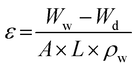
Membrane porosity (ε) was determined by gravimetric method, as defined in the following eqn (1):
| |
 | (1) |
where
Ww is a weight of wet membrane,
Wd is a weight of dry membrane,
A is a membrane effective area (4 cm
2),
ρw is water density (998 kg m
−3) and
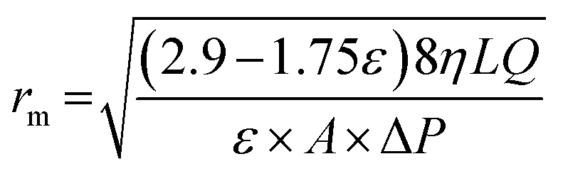
L is membrane thickness (m). The average membrane pore radius (nm) was calculated by Guerout-Elford-Ferry equation as shown in equation (
eqn (2)).
| |
 | (2) |
where
η is the water viscosity (8.9 × 10
−4 Pa s),
Q is the volume of permeated pure water per unit time (m
3 s
−1), and Δ
P is the operational pressure which is 1.4 bar.
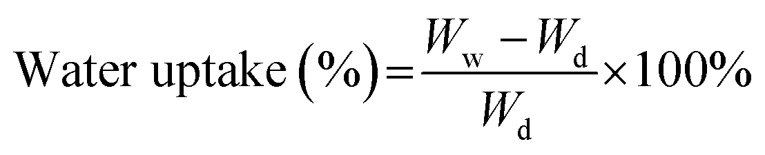
Membrane water uptake was estimated by measuring the weight difference between wet and dry membrane. Membrane coupon with surface area of 4 cm2 was dried at 80 °C for overnight and then weighed as Wd. The membrane was then soaked into DI water for 24 h. After taking out the membrane, residual water was removed gently. The weight of membrane coupon was measured immediately and recorded as Ww. Water uptake of membrane was calculated by using eqn (3) as shown below. Five membrane samples were tested for each test and the average value was taken.
| |
 | (3) |
Contact angle of each PES membrane fabricated was measured by sessile drops with contact angle analyzer (Pheonix-300, SEO Corporation). Five static contact angles were measured for each membrane sample.
2.6 Pure water flux and anti-compaction test
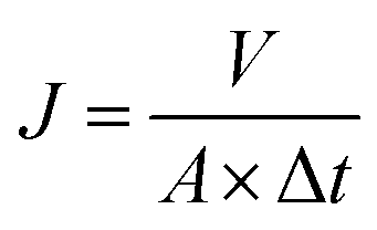
With PES membranes prepared, membrane filtration tests were conducted at dead-end filtration mode. The feed solution was pressurized into a membrane filtration cell (Millipore, effective filtration area is 0.0028 m2) at constant pressure of 1.4 bar. A permeate which is produced by the membrane was collected on a reservoir located on a digital weight balance. Accumulated permeate volume with filtration time was recorded by data acquisition system. The pure water flux (PWF) of membrane was calculated by eqn (4) below.| |
 | (4) |
where V is the permeate volume collected (L) for sampling time (Δt, h), A is the effective filtration area (m2) and Δt is time difference. Membrane compaction was also estimated by the relative difference between initial pure water flux and pure water flux stabilized using eqn (5).| |
 | (5) |
where J0 is the initial flux of membranes (L m−2 h−1) and J1 is the stable flux of membranes (L m−2 h−1).
2.7 Fouling experiment
In order to know anti-fouling properties of the PES mixed matrix membrane synthesized in this study, a BSA solution prepared (1 g L−1) was added into the dead-end filtration cell. The permeate flux decline with filtration time was measured at 1.4 bar for 60 min operation. The rejection of BSA compound was then also measured using eqn (6) as below.| |
 | (6) |
where Cf and Cp (mg L−1) are the BSA concentration in feed solution and permeate, respectively. The BSA concentration was measured with UV-VIS spectroscopy at 280 nm as wavelength.
3 Results and discussion
3.1 Characterization of sulfated TiO2 nanoparticles
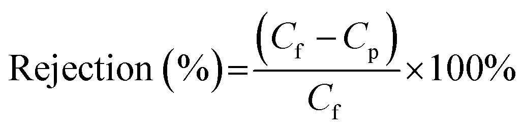
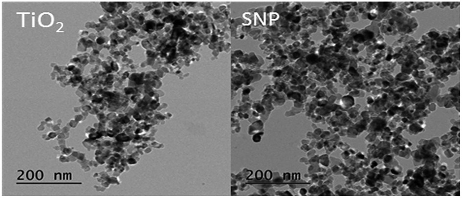
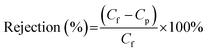
Fig. 1 shows microscopic images of the sulfated-TiO2 nanoparticles taken by Field Emission-Transmission Electron Microscopy (FE-TEM). Significant difference between sulfated-TiO2 nanoparticles and virgin TiO2 ones was not observed. The EDX analysis with the sulfated TiO2 nanoparticles detected S element, indicating that sulfating should be incorporated with TiO2 nanoparticles successfully (0.79% weight percent). The XRD results of sulfated TiO2 and virgin TiO2 nanoparticles are compared in Fig. 2. Both nanoparticles are associated with anatase and rutile crystal structure. The XRD peak appeared at 2 theta of 25, 48 and 55, which belongs to (101), (200) and (211) as anatase phase, respectively. Whereas, the peaks positioned at 2 theta of 27, 35 and 41 are related to the (110), (101) and (111) as rutile phase, respectively. Based upon XRD results, sulfating TiO2 nanoparticles do not likely affect crystal structure of the TiO2 particles significantly. The particle size distributions of synthesized TiO2 nanoparticles are shown in Fig. 3. After sulfating treatment, particle size of the TiO2 nanoparticle became smaller than the bare TiO2 particles (128.3 nm vs. 172.5 nm), indicating that the sulphated TiO2 particles in suspension had better dispersity.
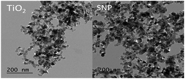 |
| | Fig. 1 TEM images of TiO2 (left) and sulfated TiO2 nanoparticles (right). | |
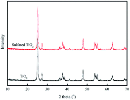 |
| | Fig. 2 XRD results with TiO2 and sulfated TiO2 nanoparticles. | |
 |
| | Fig. 3 Size distribution of sulfated TiO2 nanoparticles and non-sulfated TiO2 nanoparticles. The nanoparticles were dispersed in DI water for tests. | |
3.2 Characterization of PES mixed matrix membrane
Fig. 4 shows SEM images of PES membrane embedded with sulfated TiO2 nanoparticles and TiO2 nanoparticles at different dosages. Results show more deposit of TiO2 nanoparticles on PES membrane than that of sulfated TiO2 nanoparticles. During phase separation in membrane fabrication, the hydrophilic TiO2 nanoparticles can be migrated from the membrane pore matrix which is hydrophobic to the non-solvent (water) to reduce interfacial energy between casting solution and water. As a result, the TiO2 nanoparticles tend to be released toward the membrane surface with their aggregate forms.
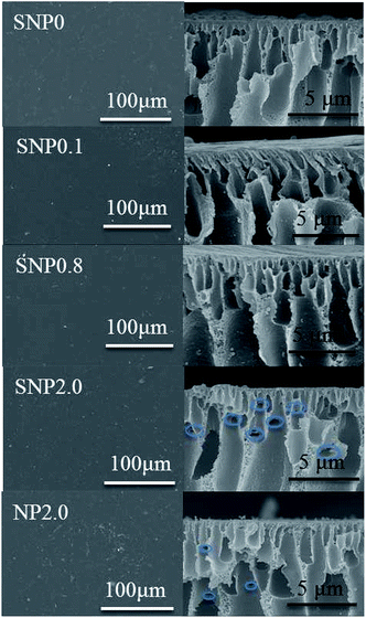 |
| | Fig. 4 Surface morphology and cross sectional view images of PES composite membranes. | |
Cross-sectional views of each PES membranes are also shown in Fig. 4. Asymmetric cross-sectional structure of the membrane consisting of a dense skin layer and porous support layer having finger-like macroporous structure was observed. Thinner skin layer as well as the appearance of lateral pores (blue circles in Fig. 4) with oval shape having horizontal orientation could result in higher membrane permeability as the sulphated TiO2 nanoparticles were applied as doping materials.24 Porosity and pore size of each membrane fabricated in this study are presented in Table 1. With TiO2 nanoparticles at 2.0 wt%, membrane porosity was reduced possibly due to membrane pore blockage caused by aggregation of the TiO2 nanoparticles.
Table 1 Membrane porosity, mean pore size, BSA rejection and surface roughness
| Membrane |
Porosity (%) |
Mean pore radius (nm) |
BSA rejection (%) |
Surface roughness (nm) |
| SNP0 |
80.2 ± 2.6 |
11.6 ± 0.9 |
96.5 ± 1.1 |
95.7 |
| SNP2.0 |
75.3 ± 1.5 |
16.6 ± 0.4 |
99.3 ± 0.2 |
65.8 |
| NP2.0 |
73.9 ± 2.0 |
14.9 ± 0.4 |
99.0 ± 0.7 |
91.9 |
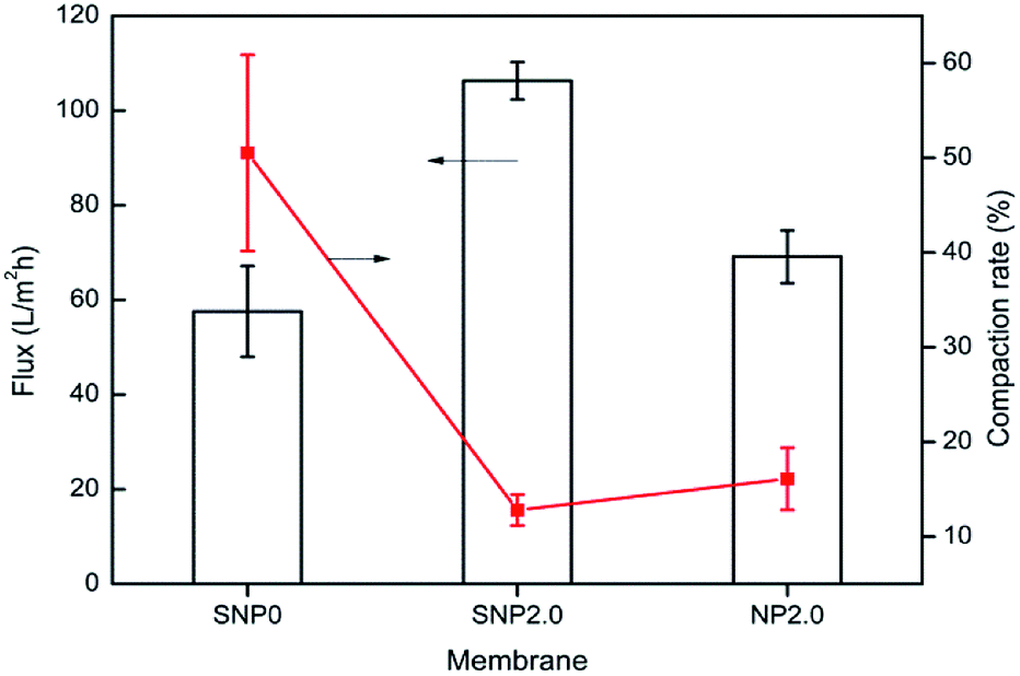
Membrane hydrophilicity was estimated by measuring contact angle and water uptake capacity. Contact angle of the bare PES membrane was 68°, but it was reduced to 57° and 53° for the TiO2 and sulfated TiO2 nanoparticles as doping material, respectively. It was found that the sulfated TiO2 nanoparticles increased hydrophilicity of PES membrane. This result corresponded to higher water uptake capacity of the PES membrane embedded with sulfated-TiO2 nanoparticles, as shown in Fig. 5. Compared to the bare PES membrane (SNP0), the SNP2.0 membrane provided better anti-compaction against transmembrane pressure (Fig. 6). Because sulfated TiO2 nanoparticles usually have strong acidity, particle aggregation should be mitigated by resisting the pull and impact from outside surroundings.
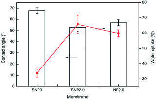 |
| | Fig. 5 Contact angle measurement and water uptake result. | |
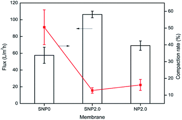 |
| | Fig. 6 Membrane pure water flux and anti-compaction properties. | |
In order to investigate the performance of the PES mixed matrix membrane fabricated in this study, the dead end filtration experiments were performed at constant pressure. The pure water flux was measured for each PES membrane fabricated. As shown in Fig. 6, the pure water flux of SNP2.0 membrane was two times higher than that obtained by bare PES membrane. This high permeate flux is associated with membrane pore size and hydrophilicity improved by doping SNP2.0. Pure water flux of SNP2.0 membrane was much higher than that of NP2.0 membrane (106 LMH vs. 69 LMH) at the same transmembrane pressure applied.
3.3 Membrane fouling tests
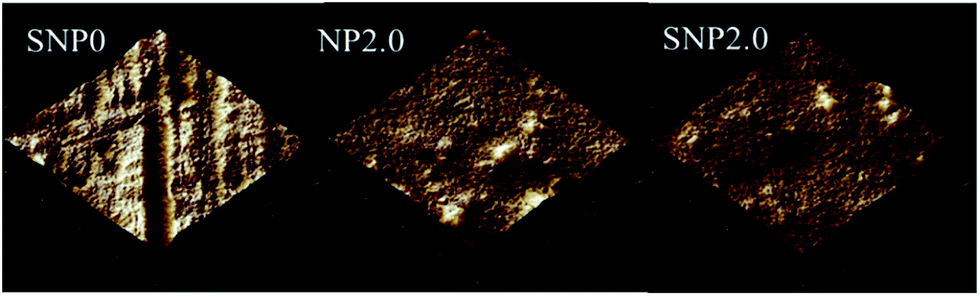
Membrane fouling is an inevitable phenomenon during membrane filtration due to the deposit of foulant on membrane surface and/or within membrane pores. At constant pressure filtration, the permeate flux should decrease with time due to the progress of membrane fouling. The fouling rate was measured by using a dead-end filtration cell with the bovine serum albumin solution (BSA, 1 g L−1). As shown in Fig. 7, the SNP2.0 membrane results in lowest fouling rate, but the rejection with BSA compound is greatest (Table 1) during 60 min of BSA filtration, there was about 40% flux decline with sulphated TiO2 nanoparticles-embedded PES membrane. Safarpour et al., observed more than 60% in flux decline with 500 mg L−1 BSA filtration with PES membrane embedded with graphene oxide/TiO2 nanoparticles.25 Fang also found that more than 80% flux decline with 1 g L−1 of BSA solution with iron–tannin-framework modified PES UF membrane.26 Since the sulfated TiO2 nanoparticles are more acidic and hydrophilic than TiO2 nanoparticles, the sulfated TiO2 nanoparticles should be combined with water molecule more easily due to their hydrogen bonds. As result, water molecules are expected to be passed through membrane pores smoothly. With AFM observations, lower surface roughness was associated with higher antifouling performance (Fig. 8). Surface roughness of the bare PES membrane (SNP0), the PES membrane embedded with sulfated-TiO2 nanoparticles (SNP2.0) and bare TiO2 nanoparticles (NP2.0) is 95.7, 65.8 and 91.9 nm, respectively. Membrane surface roughness reduces a repulsive energy barrier between membrane surface and foulant materials. Higher membrane surface roughness should trap more foulants, resulting in higher fouling rate.
 |
| | Fig. 7 Flux decline during fouling test with BSA solution. | |
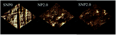 |
| | Fig. 8 AFM images of PES membrane (SNP0), PES membrane embedded with sulfated-TiO2 nanoparticles (SNP2.0) and PES membrane embedded with TiO2 nanoparticles (NP2.0) at 2 wt% dosage. | |
3.4 Effect of sulfated TiO2 dosage on membrane performance
Effect of sulfated TiO2 nanoparticles dosage on membrane performance was investigated at different dosages of nanoparticles, 0.1, 0.8 and 2.0 wt%. Overall porosity are similar to bare PES membrane (77% for SNP0.1 and 79.6% for SNP0.8). At lowest dosage of sulfated TiO2 nanoparticles (0.1 wt%), membrane porosity was similar to that of the bare PES membrane. This may be attributed to the well-dispersity of the sulfated TiO2 nanoparticles without forming their aggregate within membrane pore matrix. Highest dosage of sulfated TiO2 nanoparticles (2.0 wt%), however, decreased membrane porosity by 6% due to aggregation of the sulfated TiO2 nanoparticles within the membrane. The morphology of PES composite membranes doped with 0.1 wt% and 0.8 wt% of sulfated TiO2 nanoparticles did not show any morphological difference in cross-sectional view (Fig. 4).
Based upon membrane porosity and pure water flux, mean pore size of the membrane was calculated using Guerout-Elford-Ferry equation. It was estimated that membrane pore size was increased by increasing sulfated-TiO2 dosage to 0.1 wt%. At this dosage, exchange rate can be faster between solvent and non-solvent (water) during membrane precipitation because the sulfated-TiO2 nanoparticles can increase hydrophilicity in casting solution. As the dosage was increased to 0.8 wt%, however, membrane pore size was reduced significantly, from 22.2 ± 1.6 nm to 12.1 ± 1.1 nm. Increasing the dosage of sulfated TiO2 nanoparticles can increase a viscosity of casting solution, leading to delay exchange rate between solvent and non-solvent during membrane precipitation. Interestingly, further increase in the dosage of sulfated TiO2 nanoparticles to 2.0 wt% increased membrane pore size again (16.6 ± 0.4 nm). Viscosity effect in casting solution should be overwhelmed by membrane hydrophilicity enhanced by high dosage of sulfated-TiO2 nanoparticles.
The particle size distributions of synthesized TiO2 nanoparticles are shown in Fig. 3. After sulfating treatment, particle size of the TiO2 nanoparticle was smaller than the bare TiO2 particles (128.3 nm vs. 172.5 nm). This indicates the sulphated TiO2 particles in suspension had better dispersity. The water update capacity was 33.8, 46, 50.8 and 68.9% for SNP0, SNP0.1, SNP0.8 and SNP2.0, respectively. This result is consistent with higher membrane hydrophilicity at higher dosage of sulfated TiO2 nanoparticles as observed in this study. Additionally, anti-compaction property of the PES membrane was improved by increasing sulfated-TiO2 dosage. Results on all these information are summarized in Table 2. These phenomena can be explained by two main reasons. First, the particles with small size and large curvature can decentralize stress and impact from outside surroundings efficiently. Second, at high sulfated-TiO2 dosage, free motion of polymer chains is partly restricted by intermolecular force between polymer chains and sulfated TiO2 nanoparticles. This should help to improve dispersity of the nanoparticles in membrane pore matrix. With SNP0.1, the pure water flux of the PES membrane was about four times higher than that of bare PES membrane (SNP0) (57.6 ± 9.6 vs. 217.8 ± 11.6 L m−2 hr). However, the pure water flux was reduced to 65.6 ± 10.9 L m−2 hr as dosage of sulfated TiO2 nanoparticles was above 0.8 wt%. These observations indicate strongly that pure water flux of the PES membrane doped with sulfated-TiO2 nanoparticles should be affected more by membrane hydrophilicity than membrane pore size.
Table 2 Membrane properties and permeability of PES composite membrane doped with different filler concentration
| Membrane |
Water uptake (%) |
Contact angle (°) |
Compaction rate (%) |
Flux (L m−2 h−1) |
| SNP0 |
33.8 ± 2.6 |
67.9 ± 2.5 |
50.5 ± 10.3 |
57.6 ± 9.6 |
| SNP0.1 |
46.0 ± 2.0 |
57.6 ± 3.1 |
64.7 ± 7.7 |
217.8 ± 11.6 |
| SNP0.8 |
50.8 ± 3.1 |
55.1 ± 1.4 |
44.2 ± 10.9 |
65.6 ± 10.9 |
| SNP2.0 |
68.9 ± 6.6 |
52.9 ± 3.4 |
12.8 ± 1.6 |
106.3 ± 4.0 |
Interaction between sulfated-TiO2 nanoparticles and PES membrane is illustrated in Fig. 9a. Due to strong acidity and inductive effect by SO bond, strong hydrogen bonds should be formed between Ti–OH group on sulfated TiO2 nanoparticles and O element in PES chains. This interaction helps to improve both anti-compaction of the membrane and dispersity of the nanoparticles within membrane pore matrix.
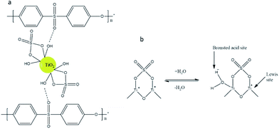 |
| | Fig. 9 Conceptual schematics to understand interaction between sulfated TiO2 nanoparticles and PES polymer chain (a), formation of Brönsted acid site and Lewis acid site with sulfated TiO2 nanoparticles (b). | |
In addition to the hydroxide group employed by TiO2 nanoparticles, the inductive effect by SO of SO42− groups can form Lewise-type acid sites and Brönsted acid sites (Fig. 9b). The Brönsted acid sites are formed by uptake of water molecules while the Lewis acid sites are formed by highly covalent property of adsorbed sulfates. Both acid sites can enhance membrane hydrophilicity with sulfated-TiO2 nanoparticles.22,27
4 Conclusions
Sulfated-TiO2 nanoparticles were synthesized by simple sulfating method and applied as doping material for PES membrane successfully. Embedding the sulfated-TiO2 nanoparticles into PES membrane improved membrane permeability with increasing pure water flux while reducing organic fouling as compared to the PES membrane embedded with bare TiO2 nanoparticles as doping material. The sulfated TiO2 nanoparticles resulted in larger membrane pore size, higher membrane hydrophilicity and better anti-compaction against transmembrane pressure compared to the bare TiO2 nanoparticles under the same dosage. However, optimum dosage of the sulfated-TiO2 nanoparticle existed with the PES membrane at 0.8 wt% above which no beneficial effect of the doping material was observed on the performance of PES membrane.
Acknowledgements
This work was supported by WCSL (World Class Smart Laboratory) research grant directed by Inha University.
Notes and references
- P. S. Goh, B. C. Ng, W. J. Lau and A. F. Ismail, Sep. Purif. Rev., 2014, 44, 216–249 CrossRef.
- A. Sotto, J. Kim, J. M. Arsuaga, G. del Rosario, A. Martínez, D. Nam, P. Luis and B. Van der Bruggen, J. Mater. Chem. A, 2014, 2, 7054–7064 CAS.
- X. Li, J. Huang, Y. Zhang, Y. Lv, Z. Liu and Z. Shu, Desalin. Water Treat., 2015, 57, 10980–10987 CrossRef.
- L. Yan, Y. Li, C. Xiang and S. Xianda, J. Membr. Sci., 2006, 276, 162–167 CrossRef CAS.
- A. Mollahosseini, A. Rahimpour, M. Jahamshahi, M. Peyravi and M. Khavarpour, Desalination, 2012, 306, 41–50 CrossRef CAS.
- Y. Zhang, X. Shan, Z. Jin and Y. Wang, J. Hazard. Mater., 2011, 192, 559–567 CrossRef CAS PubMed.
- S. S. Madaeni, S. Zinadini and V. Vatanpour, J. Membr. Sci., 2011, 380, 155–162 CrossRef CAS.
- Y. Zhang, F. Liu, Y. Lu, L. Zhao and L. Song, Desalination, 2013, 324, 118–126 CrossRef CAS.
- V. M. Gun'ko, E. F. Voronin, E. M. Pakhlov, V. I. Zarko, V. V. Turov, N. V. Guzenko, R. Leboda and E. Chibowski, Colloids Surf., A, 2000, 166, 187–201 CrossRef.
- A. Razmjou, J. Mansouri and V. Chen, J. Membr. Sci., 2011, 378, 73–84 CrossRef CAS.
- H. Song, J. Shao, Y. He, B. Liu and X. Zhong, J. Membr. Sci., 2012, 405–406, 48–56 CrossRef CAS.
- G. Zeng, Y. He, Z. Yu, Y. Zhan, L. Ma and L. Zhang, Appl. Surf. Sci., 2016, 371, 624–632 CrossRef CAS.
- Y. Zhang, L. Wang and Y. Xu, Desalination, 2015, 358, 84–93 CrossRef CAS.
- P. K. Doolin, S. Alerasool and D. J. Zalewski, Catal. Lett., 1994, 25, 209–223 CrossRef CAS.
- K. Guan, B. Lu and Y. Yin, Surf. Coat. Technol., 2003, 173, 219–223 CrossRef CAS.
- X. Wang, J. C. Yu, Y. Hou and X. Fu, Adv. Mater., 2005, 17, 99–102 CrossRef CAS.
- R. S. Rodrigo, J. M. H. Enríquez, A. C. Mares, J. A. M. Banda, R. G. Alamilla, M. Picquart and T. L. Goerne, Catal. Today, 2005, 107–108, 838–843 CrossRef CAS.
- J. Wu, Z. Cui, C. Zhao, H. Li, Y. Zhang, T. Fu, H. Na and W. Xing, Int. J. Hydrogen Energy, 2009, 34, 6740–6748 CrossRef CAS.
- M. Sgambetterra, S. Panero, J. Hassoun and M. A. Navarra, Ionics, 2013, 19, 1203–1206 CrossRef CAS.
- D. Liu, L. Geng, Y. Fu, X. Dai and C. Lü, J. Membr. Sci., 2011, 366, 251–257 CrossRef CAS.
- S. Ren, G. Sun, C. Li, S. Song, Q. Xin and X. Yang, J. Power Sources, 2006, 157, 724–726 CrossRef CAS.
- Y. Zhang, P. Cui, T. Du, L. Shan and Y. Wang, Sep. Purif. Technol., 2009, 70, 153–159 CrossRef CAS.
- Y. Zhang and P. Liu, J. Membr. Sci., 2015, 493, 275–284 CrossRef CAS.
- V. Vatanpour, S. S. Madaeni, L. Rajabi, S. Zinadini and A. A. Derakhshan, J. Membr. Sci., 2012, 401–402, 132–143 CrossRef CAS.
- M. Safarpour, V. Vatanpour and A. Khataee, Desalination, 2016, 393, 65–78 CrossRef CAS.
- X. Fang, J. Li, X. Li, S. Pan, X. Sun, J. Shen, W. Han, L. Wang and B. Van der Bruggen, J. Colloid Interface Sci., 2017, 505, 642–652 CrossRef PubMed.
- G. D. Yadav and J. J. Nair, Microporous Mesoporous Mater., 1999, 33, 1–48 CrossRef CAS.
|
| This journal is © The Royal Society of Chemistry 2017 |
Click here to see how this site uses Cookies. View our privacy policy here. 
 Open Access Article
 This Open Access Article is licensed under a Creative Commons Attribution-Non Commercial 3.0 Unported Licence
 *
*