
 Open Access Article
 This Open Access Article is licensed under a
 Creative Commons Attribution 3.0 Unported Licence
Analysis and modeling of the growth of intermetallic compounds in aluminum–steel joints
Gang Zhanga,
ManJiao Chena,
Yu Shi*a,
Jiankang Huanga and
Fuqian Yang *b
*b
aState Key Laboratory of Advanced Processing and Recycling Non-ferrous Metals, Lanzhou University of Technology, Lanzhou 730050, P. R. China. E-mail: shiyu@lut.cn
bDepartment of Chemical and Materials Engineering, University of Kentucky, Lexington, 40506, USA. E-mail: fyang2@uky.edu
First published on 1st August 2017
Abstract
In this work, we experimentally and numerically studied the microstructures and growth of intermetallic compounds (IMCs) formed in Al–Fe (aluminum–steel) joints welded by a pulsed double electrode gas metal arc welding (DE-GMAW)-brazing method. The IMCs consist of Fe2Al5 and FeAl3, with Fe2Al5 being the main compound in the joints. The thickness of an IMC layer increases with an increase of the welding current (heat input) into the base metal. EBSD measurement suggests that the preferred crystal orientation of the Fe2Al5 IMC likely provides the necessary path for Al atoms to migrate through the IMC layer for further growth of the Fe2Al5 IMC layer toward the steel substrate. The Monte Carlo method was used to simulate growth of the IMCs in the joints. Numerical results are in good accord with the experimental results, suggesting that Fe2Al5 IMC is first formed in the initial brazing interface between liquid Al and steel substrate, and then the interface between the liquid Al and steel substrate evolves into two new interfaces: one is an interface between the Fe2Al5 IMC layer and the steel substrate, and the other is an interface between the Fe2Al5 IMC layer and liquid Al. During growth of the Fe2Al5 IMC, FeAl3 IMC forms in the interface between the Fe2Al5 IMC layer and the Al and then grows into the Al. The thickness of the Fe2Al5 layer increases nonlinearly with an increase in the growth time.
1. Introduction
Al–Fe (aluminum–steel) dissimilar joints have been widely used in automotive and rail transit industries due to its light weight, which results in less energy consumption and reduces air pollution.1 But, it is a challenge to join Al to steel because of the large differences between thermal-physical properties, including melting points, thermal and electrical conductivities, thermal expansions, and limited solubility of iron (Fe) in Al. Also, the formation of brittle Al–Fe intermetallic compounds (IMCs) in Al–Fe joints can significantly deteriorate the mechanical strength of the Al–Fe joints (e.g., tensile strength, corrosion resistance, and fatigue strength), and limit structural durability.2 Understanding the formation and evolution of Al–Fe IMCs in Al–Fe joints will help to design better welding processes and optimize welding parameters for suppressing formation and growth of Al–Fe IMCs in order to produce better brazed joints and welded structures.Various methods have been developed to join Al alloy to steel, including solid-state bonding methods, such as friction welding,3 diffusion bonding,4 explosive welding5 and ultrasonic welding,6 as well as welding-brazing techniques such as gas tungsten arc welding (GTAW),7 cold metal transfer welding (CMT),8 gas metal arc welding (GMAW),9 laser welding, and laser-arc hybrid welding.10,11 Solid-state bonding methods can efficiently suppress formation of Al–Fe IMCs in a joint interface due to low heat input to the base metal. However, these methods cannot completely limit the formation of Al–Fe IMCs and can only produce Al–Fe joints with limited strength.
It has been reported that the thickness of an Al–Fe IMC layer formed in a brazed interface can be limited to less than 10 μm, which is the critical thickness of the Al–Fe IMC layer for an Al–Fe joint with good mechanical strength.12 Analysis of the microstructures of Al–Fe joints suggest that the microstructures and distribution of Al–Fe IMCs near the fusion-brazed Al–Fe joint interfaces are dependent on heat input into the base metal and play important roles in determining mechanical and/or corrosion behavior of the joints.13,14 However, there are few studies focusing on correlation between the welding current (heat input) and thickness of the Al–Fe IMC layer in joints formed by the fusion-brazing method. Especially, mechanisms for the formation and growth of Al–Fe IMCs remain elusive.
Das et al.15 proposed a theoretical–experimental method to estimate the thickness of the Al–Fe IMC layer in a lap configuration. Song et al.16 studied the microstructures of butt joints made by the TIG welding-brazing method and composition of the Al–Fe IMC layer. Madhavan et al.17 analyzed the effect of heat input on the microstructures, and the mechanical and corrosion behavior of Al–Fe joints. Zhang et al.,18 Shao et al.19 and Chen et al.20 numerically investigated formation of Al–Fe IMCs for given welding conditions from the framework of heat conduction and kinetics of solidification. However, their results did not reveal the intrinsic behavior involving formation and growth of the Al–Fe IMCs due to limited information from experimental results.
Considering the applications of Al–Fe dissimilar joints in automotive and rail transit industries, a DE-GMAW-brazing method was used in this work to join Al alloy to galvanized steel. The microstructures of the Al–Fe joints were analyzed by EBSD (electron backscatter diffraction). The Monte Carlo (MC) method incorporated with thermal and diffusion analyses was used to simulate growth of the Al–Fe IMCs.
2. Experimental details and modeling analysis
2.1 Materials
The materials used in this work were Al alloy wire (ER5356) of 1.2 mm in diameter and galvanized steel (Q235 mild steel) sheet coated with a Zn layer of 100 g m−2. Table 1 lists the chemical compositions of Q235 mild steel and ER5356 wire. The dimensions of the steel plate were 300 × 100 × 2 mm3. Prior to welding, the surface of the steel plate was cleaned with acetone to remove grease and surface residues.| Material | Mg | Cr | C | Si | Cu | Fe | Zn | S | Mn | P | Ti | Al |
|---|---|---|---|---|---|---|---|---|---|---|---|---|
| ER5356 | 5.0 | 0.1 | — | 0.3 | 0.05 | 0.40 | 0.05 | — | 0.15 | — | 0.01 | Balance |
| Q235 | — | — | 0.12 | 0.30 | — | Balance | — | 0.045 | 0.30 | 0.045 | — | — |
2.2 Welding process
Fig. 1 shows the welding process by the pulsed DE-GMAW-brazing method. Detailed information can be found in the work of Shi et al.21 Briefly, a GTAW torch is inserted between the GMAW torch and the workpiece to decouple the welding current (Ibypass) from total current (Itotal), which reduces the welding current (Imain) into the base metal, i.e., Imain = Itotal − Ibypass. This allows control of the welding current (heat input) into the base metal through control of Ibypass and stable transfer of a molten droplet even with low heat input into the workpiece. However, introduction of the bypass torch itself cannot completely meet the requirement to join Al alloy to steel, which requires further reduction of the heat input. Instead, pulsed currents are used for both main and bypass loops. Synchronously controlling current waveforms of the main and bypass currents makes it possible to precisely control heat input into the base metal, and allows free transfer of molten droplets from the wire tip to the weld pool with a welding current much less than the current needed to realize the transfer of spray metal in a conventional GMAW process. Table 2 lists the welding parameters used for the formation of four bead-on-plate weld beads. | ||
| Fig. 1 Schematic diagram of the pulsed DE-GMAW-brazing process. | ||
| Sample | Argon gas flow rate of GTAW torch (L min−1) | Argon gas flow rate of GMAW torch (L min−1) | Welding rate (m min−1) | Current duty cycle (%) | Pulse frequency (Hz) | Itotal (A) | Ibypass (A) | Imain (A) |
|---|---|---|---|---|---|---|---|---|
| #1 | 20 | 5 | 0.5 | 20 | 80 | 77 | 0 | 77 |
| #2 | 20 | 5 | 0.5 | 20 | 80 | 77 | 22 | 55 |
| #3 | 20 | 5 | 0.5 | 20 | 80 | 77 | 32 | 45 |
| #4 | 20 | 5 | 0.5 | 20 | 80 | 77 | 55 | 22 |
2.3 Characterization of microstructures
Specimens for analysis of microstructures were cut from beads along the direction perpendicular to the welding direction of the joints. The cross-section of the specimens was mechanically ground with wet-abrasive papers and polished to achieve a mirror-like surface. Surface etching was performed in a 0.5 vol% HF solution. SEM (scanning electron microscopy) was used to characterize the microstructures of the Al–Fe joints. XRD (X-ray diffraction) and EDS (energy dispersive spectrometry) were used to analyze composition of the Al–Fe IMCs, and EBSD was used to measure crystal orientation and texture of the Al–Fe IMCs.2.4 Numerical modeling
To understand formation and growth of the Al–Fe IMCs during welding, the MC method with dual layer lattices was used in numerical simulation, and the Cellular Automata (CA) theory incorporated with thermal calculation was used to analyze the fluctuation of energy over a micro-area in a liquid phase. Fig. 2 schematically shows the lattices used in the MC analysis. Migration of the interfaces was tracked from changes in the lattices.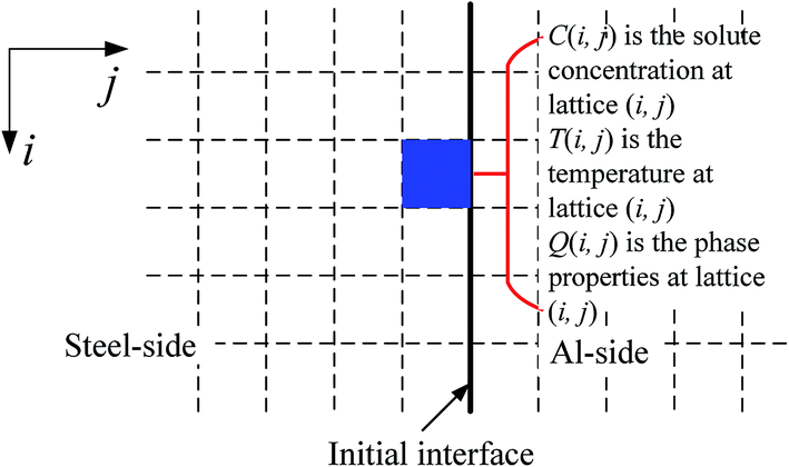 | ||
| Fig. 2 Schematic diagram of two-dimensional lattices used in the MC simulation. | ||
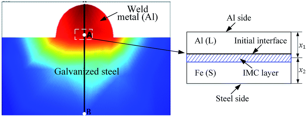 | ||
| Fig. 3 Geometrical domain for analysis of heat conduction involved in the joining of an ER5356 filler wire to a steel plate. | ||
Following the method given by Shi et al.,22,23 the following assumptions were used in the calculation of the temperature distribution during joining.
(1) The heat source linearly distributes in the Al alloy, and there is no spatial variation of temperature along the edge of the Al alloy at any time of t.
(2) Temporal variation of the edge temperature of the Al alloy can be described by a Gaussian function.
(3) Constant flux condition can be used to describe heat conduction on the edge of the steel, as suggested by Shi et al.23
(4) The heat conduction in the region shown in Fig. 3 can be described as a one-dimensional problem.
The following relationships were used in analyzing the heat conduction near the Al–Fe interface.
| Tj = Tr − qx2/λAl with q = (Tr − Ts)/(x1λFe−1 + x2λAl−1) | (1) |
| T_cell(Al) = Tr − (Tr − Tj)(n1λAl−1)(λAlx1−1) | (2) |
| T_cell(Fe) = Tj − (Tj − Ts)(n2λFe−1)(λFex2−1) | (3) |
 | (4) |
 | (5) |
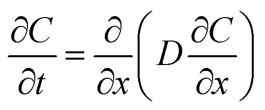
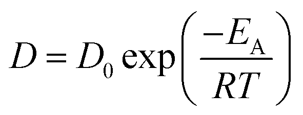
There are two diffusion processes for the diffusion of Al and Fe. One involves the diffusion of Al atoms in the steel and the diffusion of Fe in the Al alloy, and the other involves the diffusion of Al and Fe atoms through the Al–Fe IMCs.
3. Results and discussion
3.1 Microstructures
Fig. 4 shows optical images of a weld bead via the pulsed DE-GMAW-brazing method and the corresponding cross-section of the weld bead. It is evident that the Al alloy was smoothly welded to the steel plate. The surface of the joint can be approximated as a segment of a circle, which supports the schematic diagram shown in Fig. 3. | ||
| Fig. 4 Optical images of a weld bead and the corresponding cross-section of the weld bead. | ||
Fig. 5 shows SEM images of microstructures near the Al–Fe interface for Itotal = 77 A. It is evident that a layer of interphase is formed between the Al alloy and the steel, which displays two different morphologies. The interface between the interphase and the steel is a plate-like shape, and the other interface between the interphase and the Al alloy is a zig-zag shape with discrete needle-like structures distributed in the Al alloy. There are no needle-like structures in the steel. Both the thickness of the interphase layer and the number of the discrete needle-like structures decrease with a decrease of the welding current (heat input) into the base metal.
 | ||
| Fig. 5 SEM images showing the microstructures near the Al–Fe interface; (a) Ibypass = 0 A and Imain = 77 A, (b) Ibypass = 22 A and Imain = 55 A, (c) Ibypass = 32 A and Imain = 45 A, and (d) Ibypass = 55 A and Imain = 22 A. | ||
XRD analysis was performed on the surfaces of a peeled weld seam specimen. Fig. 6 shows the XRD pattern. It is interesting to note that Fe2Al5 is presented on both surfaces, suggesting that the interphase layer consists of Fe2Al5 IMC. Joining of the Al alloy to the steel plate leads to the formation of a layer of Fe2Al5 IMC, which is sandwiched between the Al alloy and steel plate.
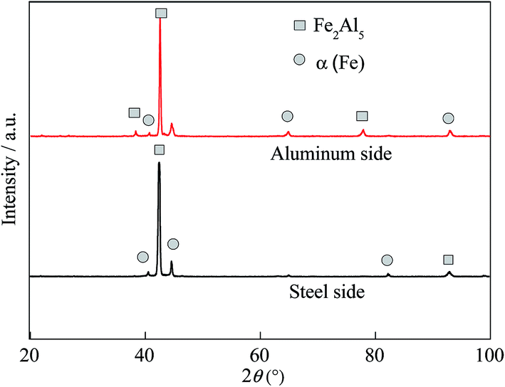 | ||
| Fig. 6 XRD pattern of the surfaces of a peeled weld seam specimen. | ||
EDS analysis was used to estimate composition of the IMCs. Fig. 7 shows the locations at which EDS analysis was performed, and Table 3 lists the compositions of these two locations. According to the data in Table 3, one can conclude that the needle-like IMCs are FeAl3, and the interphase is Fe2Al5 IMC in accord with the XRD analysis. Most IMCs are presented in the Fe2Al5 phase, which likely plays an important role in determining the mechanical behavior of the Al–Fe joints.25,26
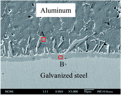 | ||
| Fig. 7 SEM image showing the locations for the EDS analysis. | ||
| Location | wt% | at% | ||
|---|---|---|---|---|
| Fe | Al | Fe | Al | |
| A | 39.97 | 56.00 | 23.94 | 69.42 |
| B | 23.72 | 68.97 | 32.72 | 76.54 |
3.2 EBSD analysis of Fe2Al5 IMC
EBSD analysis was performed on the areas of I and II shown in Fig. 4. Fig. 8 shows the EBSD mapping of area II in Fig. 4 for four different weld beads prepared with the welding parameters listed in Table 2. The Fe2Al5 IMC layer, which is sandwiched between the Al alloy and the steel, is a lath-like shape. The growth direction of the Fe2Al5 IMC layer is perpendicular to the interface between the Al alloy and the steel before joining. Preferred crystal orientation for growth is the normal direction of the (001) plane, i.e., the growth direction of the Fe2Al5 IMC formed in the pulsed DE-GMAW joining is the same as the direction of c-axis of the Fe2Al5 IMC.27 Both the size of the Fe2Al5 IMC and thickness of the IMC layer increased with an increase of the welding current (heat input) into the base metal, and the Fe2Al5 IMC is orderly distributed between the Al alloy and the steel (Fig. 8a). Such behavior is likely due to the large welding current (heat input) that causes the steel to melt and accelerates diffusion of Fe into the molten Al to form a large amount of Fe2Al5 IMC. From Fig. 8, one can note that the morphology of the Fe2Al5 IMC becomes relatively more random and disordered, and the orientation of the Fe2Al5 IMC deviates from the normal direction of the (001) plane (Fig. 8d).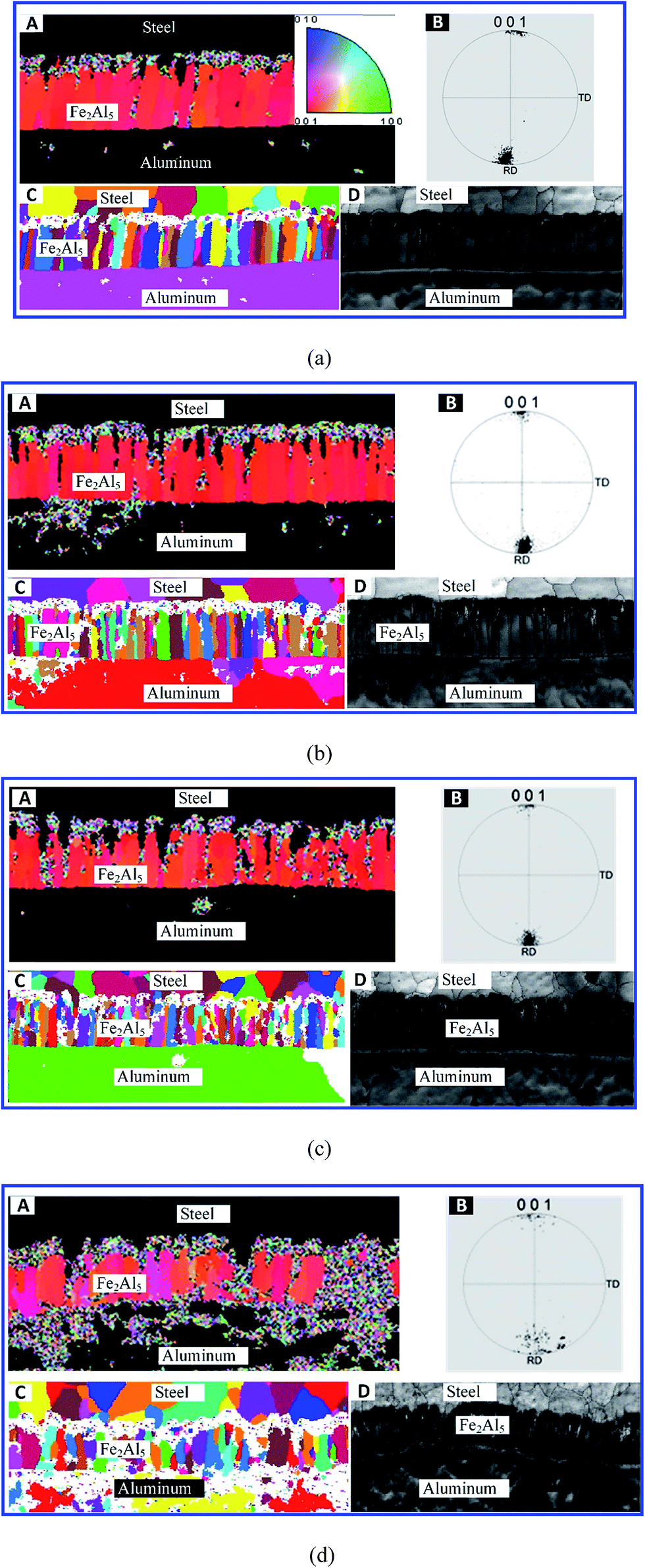 | ||
| Fig. 8 EBSD mapping of area II in Fig. 4 for four different weld beads prepared with the welding parameters listed in Table 2 (Itotal = 77 A, (A) image of crystal orientation, (B) pole figure, (C and D) EBSD color, black-white images of the joint); (a) Ibypass = 0 A and Imain = 77 A, (b) Ibypass = 22 A and Imain = 55 A, (c) Ibypass = 32 A and Imain = 45 A, and (d) Ibypass = 55 A and Imain = 22 A. | ||
Fig. 9 shows EBSD mapping of area I in Fig. 4 for four different weld beads prepared with the welding parameters listed in Table 2. The Fe2Al5 IMCs are presented in smallish lath-like shapes, and distributed more randomly than in area II for the same welding conditions. This trend is likely due to a lower temperature near the edge of the weld bead. Increasing the welding current (heat input) into the base metal did not cause any significant changes in the number of the Fe2Al5 IMCs. There is only a small portion of Fe2Al5 IMC with the growth direction along the c-axis direction of the Fe2Al5 IMC, and most Fe2Al5 IMCs are oriented disorderly (Fig. 9d). It is known that the mobility of atoms increases with an increase of temperature. Thus, at low temperature, it takes more time for Al atoms to migrate to the steel to form Fe2Al5 IMC. Also, the relatively rapid cooling of the molten Al alloy makes FeAl3 IMC act as a barrier that hinders the migration/diffusion of Al to the steel side, leading to variations of the morphology and crystal orientation of Fe2Al5 IMC, as shown in Fig. 9a and b.
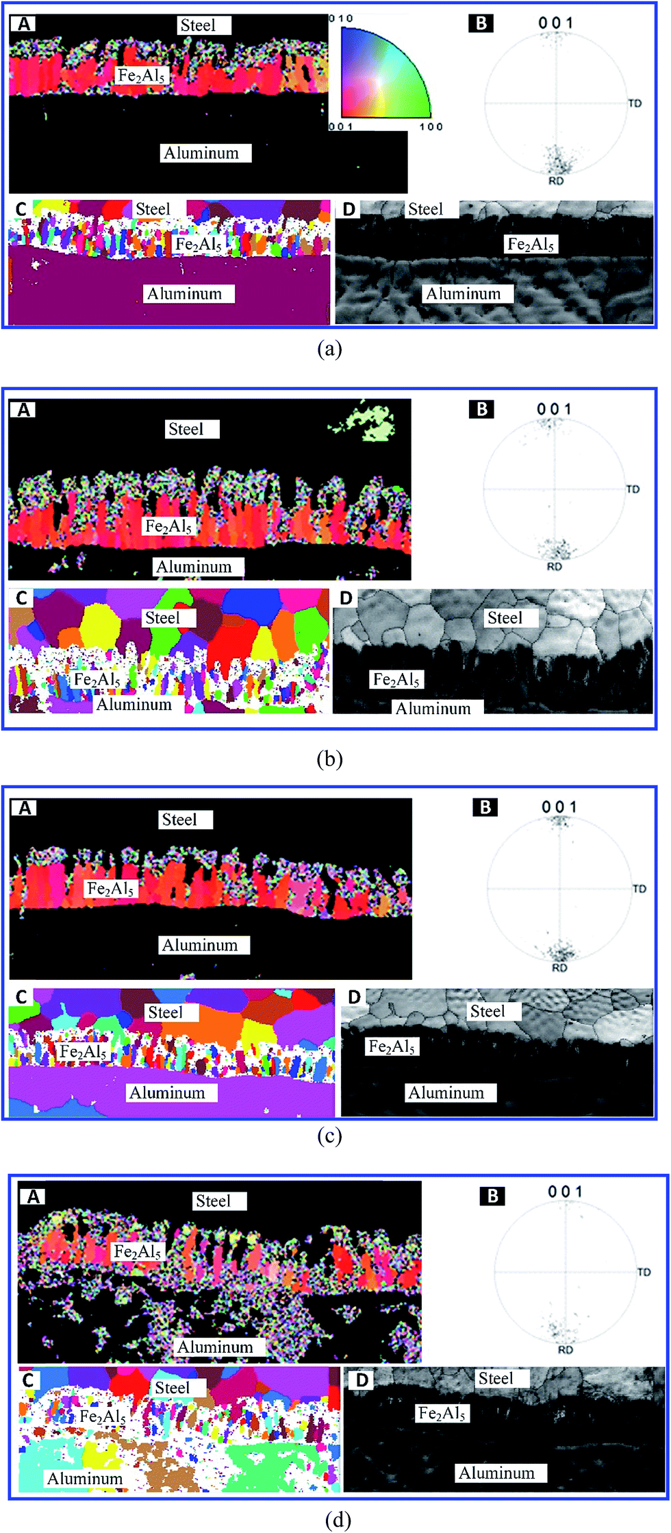 | ||
| Fig. 9 EBSD mapping of area I in Fig. 4 for four different weld beads prepared with the welding parameters listed in Table 2 (Itotal = 77 A, (A) image of crystal orientation, (B) pole figure, (C and D) EBSD color, black-white images of the joint); (a) Ibypass = 0 A and Imain = 77 A, (b) Ibypass = 22 A and Imain = 55 A, (c) Ibypass = 32 A and Imain = 45 A, and (d) Ibypass = 55 A and Imain = 22 A. | ||
In general, the formation and growth of Al–Fe IMCs is dependent on local temperature (heat input), which controls the migration rates of Al and Fe atoms. The Al–Fe IMCs become barriers to migration/diffusion of Al and Fe atoms and play an important role in determining the thickness of the IMC layer and crystal orientation of Al–Fe IMCs in the IMC layer.
3.3 Formation mechanism of the IMC layer
Based on observations and the above discussion, we propose that formation and growth of FeAl3 and Fe2Al5 IMCs in Al–Fe joints during pulsed DE-GMAW joining can be divided into four stages, as shown in Fig. 10. In the first stage (Fig. 10a), the ER5356 filler wire is melted by the main arc heat, leading to spreading of molten Al to the surface of the steel. This stage mainly involves heat and mass transfer. The second stage is associated with dissolution of Fe in molten Al alloy due to transfer of the heat from the melted Al wire and the main arc heat to the steel as well as migration/diffusion of Al atoms to the steel. Metallurgical reactions occur, resulting in formation of Fe2Al5 IMC in the interface between the Al alloy and the steel.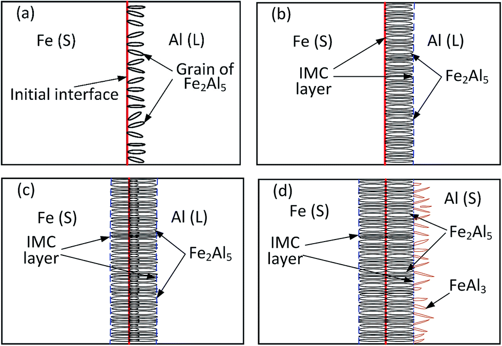 | ||
| Fig. 10 Schematic diagram of the four stages for formation and growth of the Al–Fe IMC layer; (a) the first stage, (b) the second stage, (c) the third stage, and (d) the fourth stage. | ||
In the second stage, Fe2Al5 IMC formed in the interface between the Al alloy and the steel is present in a plate-like shape, as shown in Fig. 10b. The Fe2Al5 IMC forms an IMC layer sandwiched between the Al alloy and the steel, resulting in the creation of two new interfaces, including an interface between the Fe2Al5 IMC layer and the steel and an interface between the Fe2Al5 IMC layer and the Al alloy. Fe and Al atoms need to migrate through the IMC layer in order to form new Al–Fe IMCs, which are associated with solid state diffusion instead of solid–liquid reaction. In general, Al atoms have a higher diffusivity in Fe2Al5 IMC than iron atoms. Growth of the Fe2Al5 IMC layer is mainly controlled by the migration/diffusion of Al. This trend leads to the third stage: the formation of a large number of Fe2Al5 IMCs in the steel and increase in the thickness of the IMC layer, as shown in Fig. 10c.
With formation of the Fe2Al5 IMC layer, a limited number of Fe atoms migrate to the Al alloy. This results in formation of FeAl3 in the Al alloy around the interface between the Fe2Al5 IMC layer and the Al alloy instead of the Fe2Al5 IMC. The anisotropic characteristics of FeAl3 lead to formation of needle-like structures, as shown in Fig. 10d. Note that the formation of FeAl3 IMC is limited by solid-state diffusion and the decrease of reaction temperature during solidification of the Al alloy.
3.4 Numerical simulation of the growth of Al–Fe IMCs
The MC method was used to simulate formation and growth of the IMC layer observed in the pulsed DE-GMAW joining of the Al alloy and steel. In the simulation, 400 × 600 quadrilateral meshes were used, and the length of the unit lattice was 0.1 μm. Fixed boundary conditions were used on the edges of the Al alloy and steel. Sampling frequency and simulation time were 5 MHz and 4 s, respectively. The parameters used in the analysis were from He et al. work.28Fig. 11 shows temporal variation of the IMC layer sandwiched between Al and steel substrates at different times for a welding current of 55 A. It is evident that only Fe2Al5 IMC is present at the early stage, and randomly distributes near the interface between the Al and steel. From Fig. 11a and b, note that the nucleation and growth of Fe2Al5 IMCs occur concurrently, resulting in the formation of equiaxed Fe2Al5 IMCs with a portion of the IMCs in the Al alloy in a short time period. For the growth (simulation) time being 2.8 s, FeAl3 IMC forms due to a decrease of the temperature to the melting point of Al. This result is in accord with the experimental observation and consistent with results reported by Zhang et al.18 From Fig. 11c, one can note an increase of the Fe2Al5 IMC layer due to migration of Al through the Fe2Al5 IMC layer to the steel, which supports the experimental observation.
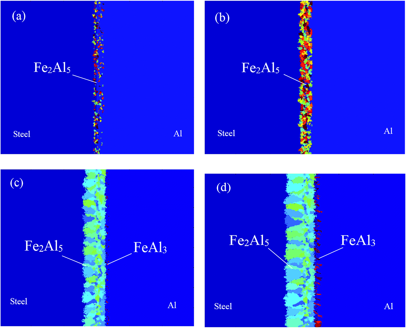 | ||
| Fig. 11 Temporal variation of the IMC layer sandwiched between Al and steel substrates (Imain = 55 A, Ibypass = 22 A); (a) t = 0.4 s, (b) t = 1.2 s, (c) t = 2.8 s and (d) t = 4 s. | ||
Fig. 11d presents the final morphology of the Al–Fe IMCs with thickness of the IMC layer being ∼11 μm. The Fe2Al5 IMC layer is a plate-like shape, and FeAl3 IMC discretely distributes in the Al alloy in a needle-like shape. It is important to note that the Fe2Al5 IMC grows towards the steel and is present in a columnar structure, similar to structures shown in Fig. 5 and there is a preferred direction for growth of the Fe2Al5 IMC.
Fig. 12 shows numerical results of the morphologies of IMCs at a growth (simulation) time of 4 s for two different welding currents (Itotal = 77 A). It is evident that the thickness of the Fe2Al5 IMC layer decreases with a decrease of the welding current (heat input) into the base metal in accord with the experimental observation (Fig. 5). Also, large welding current (heat input) promotes formation of FeAl3 IMC in the Al alloy due to Fe atoms being able to migrate through the Fe2Al5 IMC layer to reach the Al alloy at high temperature. To hinder formation of FeAl3 IMC and reduce thickness of the Fe2Al5 IMC layer, one needs to reduce the welding current (heat input) into the base metal.
 | ||
| Fig. 12 Numerical results of the morphologies of IMCs at a growth (simulation) time of 4 s for two different welding currents: (Itotal = 77 A); (a) Ibypass = 22 A, Imain = 55 A, and (b) Ibypass = 55 A, Imain = 22 A. | ||
Fig. 13a shows numerical results of variation of the thickness of the Fe2Al5 IMC layer with simulation (growth) time. According to Fig. 13a, growth of the Fe2Al5 IMC layer can be divided into three stages. The first stage is mainly controlled by nucleation of Fe2Al5 IMC with a small growth rate. Following the first stage is the second stage with fast growth of the Fe2Al5 IMC layer. The growth rate of the Fe2Al5 IMC layer first increases with an increase of simulation (growth) time, reaches the maximum, and then decreases with an increase of simulation (growth) time. In this stage, growth of the Fe2Al5 IMC is associated with dissolution of Fe in the molten Al alloy and fast migration/diffusion of Fe. In the third stage, the local temperature decreases due to solidification, and Al atoms migrate through the Fe2Al5 IMC layer, which reduces the migration rate of Al and growth rate of the Fe2Al5 IMC layer.
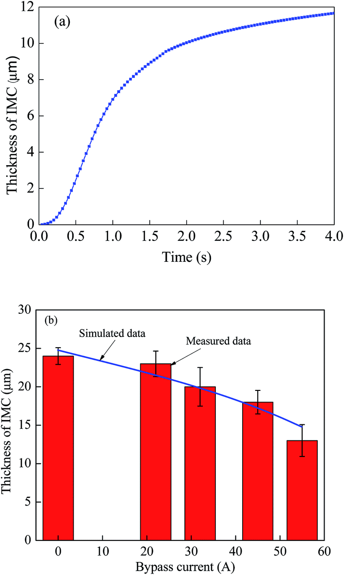 | ||
| Fig. 13 (a) Variation of the thickness of the Fe2Al5 IMC layer with a simulation time (Imain = 55 A, Ibypass = 22 A), and (b) comparison between numerical results (t = 4 s, Itotal = 77 A) and experimental results (Itotal = 77 A). | ||
Fig. 13b shows comparison between numerical results for a simulation time of 4 s and total current of 77 A, and the experimental results for total current of 77 A. It is evident that the numerical results are in good accord with the experimental results, which suggests that assumptions used in the numerical calculation are reasonable. According to the results shown in Fig. 13b, the thickness of the Fe2Al5 IMC layer decreases with an increase (decrease) of the welding current (heat input) into the bypass (main) circuit. The welding current (heat input) plays an important role in controlling growth of the Al–Fe IMCs. One can use pulsed DE-GMAW joining to control formation and growth of Al–Fe IMCs in order to control the mechanical strength of Al–steel joints.
4. Conclusions
Intermetallic compounds play an important role in determining the mechanical strength of dissimilar metallic joints. The pulsed DE-GMAW-brazing process was used in this work to join an Al alloy to a steel plate. Formation and growth of Al–Fe IMCs in the Al–steel joints was studied experimentally and numerically. Important conclusions are summarized below.(1) Both Fe2Al5 and FeAl3 IMCs form during the joining. There is a large portion of Fe2Al5 IMC which forms an IMC layer. The thickness of the Fe2Al5 IMC layer increases with an increase of welding current (heat input) into the base metal.
(2) EBSD analysis reveals that a distribution of morphology and size of Fe2Al5 IMCs exist in an Al–Fe joint. With high welding current (heat input) into the base metal, Fe2Al5 IMC is present in a lath-like shape with relatively orderly distribution. There is a preferred direction for growth of the Fe2Al5 IMC, which is parallel to the normal direction of the (001) plane.
(3) Formation and growth of Al–Fe IMCs can be divided into three stages: (1) nucleation of Fe2Al5 IMC in the interface of the Al alloy and steel, (2) fast growth of the Fe2Al5 IMC layer associated with dissolution of Fe in the molten Al alloy and fast migration/diffusion of Fe, and (3) slow growth of the Fe2Al5 IMC controlled by diffusion of Al atoms through the Fe2Al5 IMC layer. During solidification, FeAl3 IMC forms in the Al alloy near the interface between the Fe2Al5 IMC layer and Al.
(4) The MC method was used to simulate the formation and growth of the Al–Fe IMCs. The numerical results are in good accord with the experimental results, and support proposed mechanisms for formation and growth of Al–Fe IMCs in Al–Fe joints. The thickness of the Fe2Al5 IMC layer increases nonlinearly with an increase of the simulation (growth) time.
Acknowledgements
This work is funded by the National Natural Science Foundation of China [Grant No: 61365011, 2014; Grant No: 51675256, 2016].References
- G. Pardal, S. Meco, S. Ganguly, S. Williams and P. Prangnell, Int. J. Adv. Manuf. Tech., 2014, 73, 365–373 CrossRef.
- R. Taban, J. E. Gould and J. C. Lippold, Mater. Des., 2010, 31, 2305–2311 CrossRef.
- H. Das, S. Basak, G. Das and T. K. Pal, Int. J. Adv. Manuf. Tech., 2013, 64, 1653–1661 CrossRef.
- D. Travessa, M. Ferrante and G. Ouden, Mater. Sci. Eng., A, 2002, 337, 287–296 CrossRef.
- M. Acarer and B. Demir, Mater. Lett., 2008, 62, 4158–4160 CrossRef CAS.
- J. Tsujino, T. Ueoka, T. Kashino and F. Sugahara, Jpn. J. Appl. Phys., 1999, 38, 4254–4255 CrossRef CAS.
- R. Borrisutthekul, P. Mitsomwang, S. Rattanachan and Y. Mutoh, Energ. Res. J., 2010, 1, 82–88 CrossRef.
- R. Cao, G. Yu, J. H. Chen and P. C. Wang, J. Mater. Process. Technol., 2013, 213, 1753–1763 CrossRef CAS.
- Y. C. Su, X. M. Hua and Y. X. Wu, Mater. Sci. Eng., A, 2013, 578, 340–345 CrossRef CAS.
- M. Sonia, G. Supriyo, W. Stewar and M. Norman, J. Mater. Eng. Perform., 2014, 23, 3361–3370 CrossRef.
- G. L. Qin, Z. Lei, B. L. Su and X. M. Meng, J. Mater. Process. Technol., 2014, 214, 2684–2692 CrossRef CAS.
- S. Yang, J. Zhang, J. Lian and Y. Lei, Mater. Des., 2013, 49, 602–612 CrossRef CAS.
- S. Niu, S. Chen, H. G. Dong and D. S. Zhao, J. Mater. Eng. Perform., 2016, 25, 1839–1847 CrossRef CAS.
- Y. Shi, J. Li, G. Zhang, J. K. Huang and Y. F. Gu, J. Mater. Eng. Perform., 2016, 25, 1916–1923 CrossRef CAS.
- A. Das, M. Shome, S. F. Goecke and A. De, Sci. Technol. Weld. Joining, 2016, 21, 303–309 CrossRef CAS.
- J. L. Song, S. B. Lin, C. L. Yang and G. C. Ma, Mater. Sci. Eng., A, 2009, 509, 31–40 CrossRef.
- S. Madhavan, M. Kamaraj, L. Vijayaraghavan and K. S. Rao, Trans. Indian Inst. Met., 2016, 1–8 Search PubMed.
- H. T. Zhang, J. C. Feng and P. He, Mater. Sci. Technol., 2008, 24, 1346–1349 CrossRef CAS.
- L. Shao, Y. Shi, J. K. Huang and S. J. Wu, Mater. Des., 2015, 66, 453–458 CrossRef CAS.
- M. J. Chen, J. K. Huang, C. C. He, Y. Shi and D. Fan, Acta Metall. Sin., 2016, 52, 113–119 CAS.
- Y. Shi, G. Zhang, Y. Huang, L. H. Lu, J. K. Huang and Y. Shao, Weld. J., 2014, 93, 216-s–224-s Search PubMed.
- Y. Shi, R. H. Han, J. K. Huang and Y. Shao, J. Manuf. Sci. Eng., 2014, 136, 024502 CrossRef.
- Y. Shi, R. H. Han, J. K. Huang and D. Fan, Acta Phys. Sin., 2012, 61, 020205 Search PubMed.
- Y. Shi, M. J. Chen, J. K. Huang, Y. F. Gu and D. Fan, Int. J. Mod. Phys. B, 2016, 30, 1650014–1650022 CrossRef CAS.
- H. Springer, A. Kostka, E. J. Payton, D. Raabe, A. Kaysser-Pyzalla and G. Eggeler, Acta Mater., 2011, 59, 1586–1600 CrossRef CAS.
- J. J. Zhang, W. Liang and H. T. Li, RSC Adv., 2015, 127, 104954–104959 RSC.
- U. Burkhardt, Y. Grin and M. Ellner, Acta Crystallogr., Sect. B: Struct. Sci., 1994, 50, 313–316 CrossRef.
- C. C. He, J. K. Huang, Y. Shi and D. Fan, J. Jilin Univ., 2014, 44, 1037–1041 Search PubMed.
| This journal is © The Royal Society of Chemistry 2017 |