 Open Access Article
Creative Commons Attribution 3.0 Unported Licence
Silver particle-loaded nickel oxide nanosheet arrays on nickel foam as advanced binder-free electrodes for aqueous asymmetric supercapacitors†
Shuxing Wua,
Kwan San Hui b,
Kwun Nam Hui
 c,
Je Moon Yun
 d and
Kwang Ho Kim
 *ad
*ad
aSchool of Materials Science and Engineering, Pusan National University, San 30 Jangjeon-dong, Geumjeong-gu, Busan 609-735, Republic of Korea. E-mail: kwhokim@pusan.ac.kr; Fax: +82 5 1514 4; Tel: +82 51 510 3391
bSchool of Mathematics, University of East Anglia, Norwich NR4 7TJ, UK
cInstitute of Applied Physics and Materials Engineering, University of Macau, Avenida da Universidade, Taipa, Macau, China
dGlobal Frontier R&D Center for Hybrid Interface Materials, Pusan National University, 30 Jangjeon-dong, Geumjung-gu, Busan 609-735, South Korea
First published on 29th August 2017
Abstract
Conductive metal loading is an efficient approach for enhancing the electric conductivity of redox-active transition-metal oxide electrodes. In this study, Ag particle-loaded NiO/nickel foam (Ag-NiO/NF) composites were fabricated using a green chemistry method. The anchored Ag particles standing on the surface of NiO nanosheet arrays helped improve the electrical conductivity and were thus beneficial for supercapacitors (SCs). The as-developed Ag-NiO/NF electrode delivered a specific capacitance of 1254.9 F g−1 at the current density of 1 A g−1, which is higher than that of NiO/NF electrode (946.3 F g−1). Using such Ag-NiO/NF as a positive electrode, we further fabricated aqueous asymmetric SC devices with reduced graphene oxide as a negative electrode. Owing to the efficient electron transport and short ion diffusion paths in the designed electrode, the devices exhibited a high specific capacitance of 97.9 F g at 1 A g−1 with a high energy density of 26.7 W h kg−1 at a power density of 1017.1 W kg−1 and great cyclic stability.
1. Introduction
In recent years, supercapacitors (SCs) have received increasing attention due to their high power density, fast charge/discharge rate, and long cycle life. SCs can be divided into two categories based on their energy storage mechanism: electrical double-layer capacitors (EDLCs) and pseudocapacitors. EDLCs store charge at the electrode/electrolyte interface via reversible ion adsorption on high-surface-area electrode materials such as activated carbon, carbon nanotube (CNT), and graphene.1 Pseudocapacitors use fast and reversible surface or near-surface reactions for charge storage.2 Pseudocapacitors can exhibit approximately 10–100 times higher capacitance than EDLCs.3 The electrochemical performance of SCs mainly depends on their electrode materials. Therefore, the development of advanced electrode materials has become an active research field in the areas of SCs.Transition metal oxides (such as NiO, Co3O4, MnO2, and V2O5), polyoxometalates (such as NiCo2O4 and MnCo2O4), and electronically conducting polymers (such as polyaniline as polypyrrole) have been widely investigated because of their high energy density.4–8 NiO has attracted significant attention due to its intriguing characteristics such as ultrahigh theoretical specific capacitance (2584 F g−1), environmental friendliness, low cost, abundance on earth, and ease and wide range of fabrication strategies.7,9–11 However, NiO shows low electrical conductivity (∼10−4 S cm−1) and experiences large volume change during the charge/discharge process.12 Considerable research effort has been devoted to prepare new composite structures to resolve these problems; for example, NiO is combined with highly conductive materials, including active carbon,13,14 CNT,15,16 and graphene.17 However, these methods usually involve the use of polymer binders. The addition of polymer binder will inevitably increase the “dead volume” and “dead weight” in electrode materials.18,19 An ideal scheme is the use of binder-free (self-supported) electrodes, which are constructed by direct integration of electroactive materials on current collectors, such as nickel foam.20 Improved cycle life and rate capability are achieved through fabricating NiO-based binder-free electrodes, but the capacitances are still low. Gonzalez et al. prepared NiO/nickel foam by use of a simple, green, and cost-effective electrophoretic deposition, thereby obtaining a low specific capacitance of 192 F g−1.21
The performance of SCs can be enhanced by compositing the NiO/nickel foam with noble metals, such as Pt, Au, and Ag. Ag-loaded composites have received much interest because Ag is more electrically conductive and low cost compared with Au and Pt. As a noble metal, Ag particles can produce electron transfer channels because of their outstanding electronic conductivity and durability.22,23 They also enhance the proton (H+) diffusion throughout the electrode.24 Vanitha et al. prepared Ag anchored CeO2/graphene nanocomposite; the nanocomposite electrode shows a high specific capacitance of 710.42 F g−1 at current density of 0.2 A g−1, which is nearly twofold higher than CeO2/graphene nanocomposite.25 Ma et al. synthesized Ag/MnO2/graphene ternary nanocomposite; the ternary nanocomposite exhibits high specific capacitance of 467 F g−1, which is much higher than that of MnO2/graphene nanocomposite (293 F g−1).26
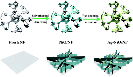
In this study, we synthesized interconnected NiO nanosheets supported by nickel foam (NiO/NF) through a facile solvothermal method combined with a post-annealing process. Ag particles were loaded on the NiO/NF by use of a wet chemical reduction method of aqueous AgNO3 solution. Scheme 1 shows a schematic of the fabrication process. Significant improvement was obtained after the loading of Ag particles. The Ag particle-loaded NiO/nickel foam (Ag-NiO/NF) electrode exhibited high specific capacitance (1254.9 F g−1 at 1 A g−1 and 914.3 F g−1 at 20 A g−1) and good cycling stability (83.2% capacitance retention over 3000 cycles). Asymmetric SCs, which were comprised of Ag-NiO/NF as the positive electrode, reduced graphene oxide (rGO)7 as the negative electrode, and 6 M KOH aqueous solution as the electrolyte, were fabricated. The aqueous asymmetric SCs yielded a high specific capacitance of 97.9 F g at 1 A g−1 and a specific energy density of 26.7 W h kg−1 at a power density of 1017.1 W kg−1 and retained 77.8% of its initial capacitance after 3000 cycles.
2. Experimental section
2.1 Materials preparation
All chemicals used in this study were of analytical grade and were purchased from Sigma-Aldrich. NF were cleaned using acetone, concentrated HCl, ethanol and deionized (DI) water for 15 min. NiO nanosheets were synthesized directly on the NF (2 × 2 cm2) by immersing into the solution with Ni(NO3)2·6H2O (0.7 g), urea (0.2 g), and ethanol (40 mL). The mixture was transferred into 50 mL autoclave with a Teflon liner at 180 °C and was then kept for 15 h. The obtained product was washed in an ultrasound bath with ethanol and DI water and dried at 60 °C for 12 h. The samples were subsequently annealed in air at 300 °C for 3 h to obtain nickel foam-supported NiO nanosheet arrays. The area density of NiO was nearly 1.91 mg cm−2. Ag-NiO/NF was fabricated using the wet chemical reduction method. In a typical procedure, the as-prepared NiO/NF (2 × 2 cm2) was immersed in AgNO3 aqueous solution (10 mL, 0.01 M) and then heated at 100 °C for 5 h. Finally, the sample was washed with DI water and dried at 60 °C for 12 h.2.2 Materials characterization
The products were measured by X-ray diffraction (XRD) on a Rigaku MPA-2000 X-ray diffractometer with Cu Kα radiation (λ = 1.5418 Å) for the phase analysis. Scanning electron microscopy (SEM, Hitachi, S-4800) and transmission electron microscopy (TEM, FEI Talos, USA) were used to observe the morphology of the samples. X-ray photoelectron spectroscopy (XPS) was performed with the Thermo VG Escalab 250 photoelectron spectrometer.2.3 Electrochemical tests
Ag-NiO/NF was directly used as the working electrode. Electrochemical measurements were carried out on an electrochemical working station (IviumNstat, Ivium Technologies) in a three-electrode system. The electrolyte was 6.0 M KOH aqueous solution, and the solution was degased for 30 min using a sonicator. Saturated calomel electrode (SCE, Hg/Hg2Cl2) and Pt electrode were used as the reference and counter electrode, respectively. Cyclic voltammetry (CV), galvanostatic charge/discharge (GCD), and electrochemical impedance spectroscopy (EIS) were applied to confirm the capacitive behavior of Ag-NiO/NF electrodes. The EIS was conducted at an amplitude of 5 mV in the frequency range of 100 kHz to 10 mHz. The obtained GCD curves were used to calculate the specific capacitance (Cs) in accordance with the following equation:27
 | (1) |
The performance of asymmetric SCs was also measured using CV and GCD. The anode electrode was fabricated mixing 85 wt% of rGO, 10% wt% of acetylene black, and 5% poly(tetrafluoroethylene). The energy (E) and power (P) densities were calculated using the following equations:
 | (2) |
 | (3) |
3. Results and discussion
Ag particles were synthesized by wet chemical reduction without the presence of reducing agents. Recently, Nishimura et al. demonstrated that NaOH accelerates the reduction of Ag+ ions and nucleation of metallic Ag nanoparticles through the formation of Ag2O intermediate.28 In the current study, the –OH on the surface of NiO nanosheets caused the generation of Ag2O (eqn (4)).29 The self-redox reaction of Ag2O could occur under the influence of indoor light. The photo-generated electrons and holes in Ag2O could facilitate its redox reaction toward the generation of metallic Ag particles, as indicated in eqn (5) and (6).| Ag+ + OH⋯NiO → AgOH⋯NiO → Ag2O⋯NiO | (4) |
| Ag2O + hv (indoor light) → h+ + e− | (5) |
| Ag2O + h+ + e− → Ag + O2 | (6) |
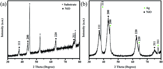
Fig. 1 shows the XRD patterns of NiO/NF and Ag-NiO/NF. NiO was superimposed on the pattern of NF substrate (Fig. 1a). The XRD peaks of the NiO nanosheets corresponded to the cubic NiO phase (JCPDS no. 65-2901) and confirmed the formation of a highly crystalline structure after annealing at 300 °C. It was demonstrated that surface redox reactivity of an electrode material depends on its crystallinity, which can be optimized using the annealing temperature.30 Previous works have shown that NiO annealed at 300 °C presents the highest electrochemical performance.31,32 Fig. 1b shows the XRD pattern of the Ag-NiO scraped from the substrate. The peaks located at around 38.1, 44.3, 64.5, and 77.4 could be indexed as the (111), (200), (220), and (311) planes of metal Ag (JCPDS no. 65-2871), respectively. The remaining diffraction peaks were consistent with the planes of NiO.
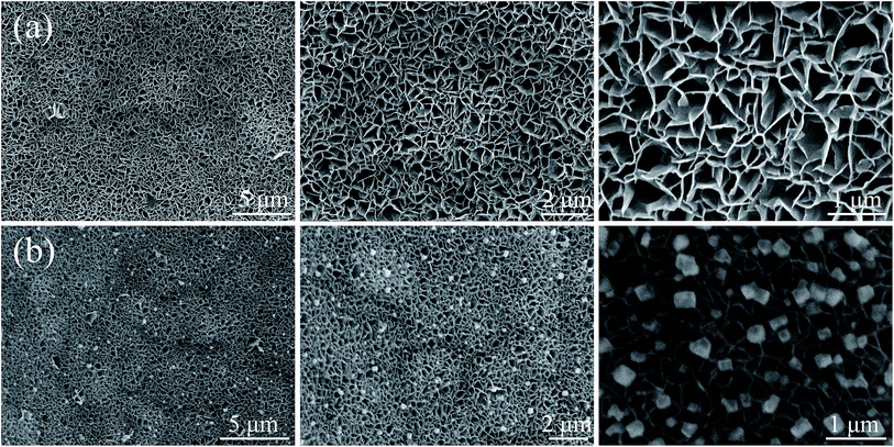
Fig. 2 shows the microstructures of NiO/NF and Ag-NiO/NF at different magnifications. NF was used as the current collector and provided efficient pathway for electron transport and reduced the diffusion resistance of the electrode due to its high electrical conductivity and 3D cross-linked structure.33 After the solvothermal treatment and a subsequent annealing process, NiO nanosheets were grown uniformly on the nickel foam with a high density. These nanosheets possessed an average thickness of approximately 40 nm. These nanosheets connected with one another and aligned vertically, thereby resulting in the formation of porous structures. The porous NiO nanosheet arrays could offer effective penetration of electrolyte and abundant electroactive sites for redox reactions. In addition, the interconnected arrays could maintain the structural stability by relaxing volume expansion during the charge/discharge process. Compared with the SEM images of NiO/NF and Ag-NiO/NF in Fig. 2b, the interconnected arrays of NiO nanosheet were fully retained and Ag particles were uniformly deposited on the surface of NiO nanosheet arrays. The Ag particles could act as bridge for electron transfer, thus, electrochemical performance of NiO nanosheets could be enhanced.
From the TEM image of Ag-NiO/NF sample, Ag particles were found loaded onto the surface of NiO nanosheet (Fig. 3a). Fig. 3b elucidates the thin nature of NiO nanosheets by the folding silk-like morphology with curling folded edges and transparent feature. The selected-area electron diffraction (SAED, selected area: ∼200 nm in diameter) exhibited polycrystalline rings, and the diffraction rings could be indexed as the (111), (200), (220), and (311) planes of the NiO phase (Fig. 3c). Fig. 3d shows a typical high-resolution TEM (HRTEM) image of NiO nanosheets. The lattice spacing of 0.21 nm corresponded to the (200) plane of NiO. Fig. 3e shows the Ag particles of the surface of the NiO nanosheet. The lattice spacing was 0.23 nm, which corresponded to the lattice spacing of the (111) planes for the Ag phase (Fig. 3f).
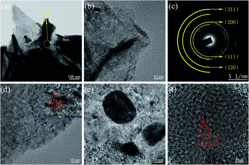 | ||
| Fig. 3 TEM image of Ag-NiO/NF (a), HRTEM images (b and d) of NiO nanosheet, SAED pattern of NiO (c), and HRTEM images of metallic Ag (e and f). | ||
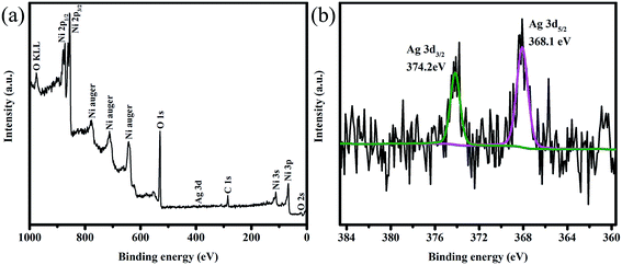
The surface states of Ag-NiO/NF were examined by XPS. The typical spectrum indicated the existence of Ni, Ag, C and O elements (Fig. 4a). The Ag 3d core level spectrum is shown in Fig. 4b. Two peaks observed at 374.2 and 368.1 eV could be attributed to Ag 3d3/2 and Ag 3d5/2, respectively. These values and the 6.1 eV splitting of the 3d doublet signal suggest the existence of metallic Ag, which also agree with previous reports.34,35
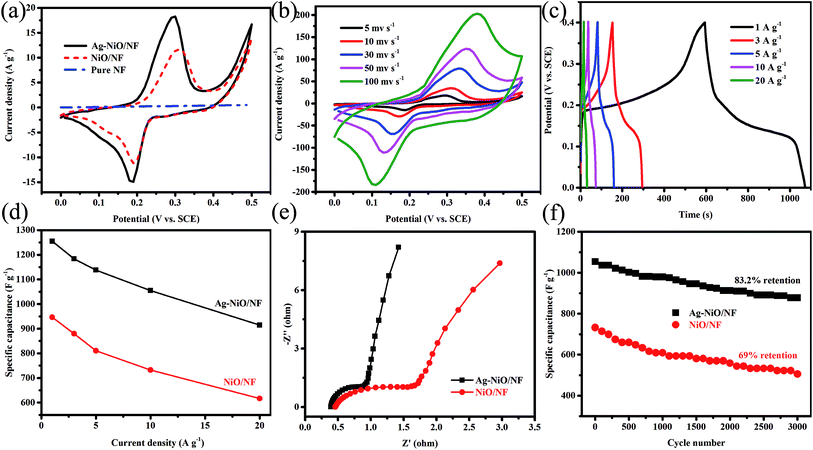
We further systematically studied the electrochemical performance of the electrodes in terms of CV, EIS, and GCD. Fig. 5a shows the CV curves of bulk NF, NiO/NF, and Ag-NiO/NF at a scan rate of 5 mV s−1. The straight line (flattened due to scale difference) was observed for pure NF; therefore, the capacitance of NF is negligible. In the case of NiO/NF and Ag-NiO/NF, well-defined redox from 0 V to 0.5 V versus SCE was observed, which originated from the faradaic reactions of Ni2+/Ni3+ associated with OH− (eqn (7)).36
| Ni2+ + OH− ↔ Ni3+ + e− | (7) |
Notably, the CV curves of NiO/NF and Ag-NiO/NF showed symmetrical shapes; therefore, the faradaic reaction of Ni2+/Ni3+ is responsible for the improved capacitance performance. The CV curves of Ag-NiO/NF electrode had a larger integral area than those of the NiO/NF electrode; therefore, Ag-NiO/NF electrode exhibits superior electrochemical capacitance. Furthermore, the high electrochemical properties of the Ag-NiO/NF electrode are attributed to the loading of Ag particles providing rapid electronic pathways. Fig. 5b shows the typical CV curves of as-synthesized Ag-NiO/NF electrode at sweep rates of 5, 10, 30, 50, and 100 mV s−1. A pair of redox peaks with symmetric characteristic could be identified in the CV curves, suggesting a high reversibility of the fast charge/discharge response. The peak current significantly increased with the increase in sweep rate. The shape of the CV curves was insignificantly influenced by the increasing sweep rate due to the enhanced electrolyte ions diffusion from open 2D structure of NiO nanosheets and the superior electronic conductivity of NF and Ag particles.
Fig. 5c shows the GCD curves of the Ag-NiO/NF electrode at different current densities in the range of 1–20 A g−1 in a potential window of 0–0.4 V. A distinct plateau could be observed in the GCD curves, which corresponded to the forward reaction in eqn (7).37 The GCD curves displayed great symmetry; therefore, excellent reversible redox reactions occur. The gravimetric capacitances of NiO/NF electrode (Fig. S1†) and Ag-NiO/NF electrode (Fig. 5d) were further calculated and plotted as a function of current density. The specific capacitances of Ag-NiO/NF electrode were 1254.9, 1183.2, 1137.6, 1054.6, and 914.3 F g−1 at different current densities of 1, 3, 5, 10, and 20 A g−1, respectively. Impressively, Ag-NiO/NF electrode preserved approximately 73% of specific capacitance delivered at 1 A g−1 as the current density increased to 20 A g−1, indicating high-rate capability. The increase in current density led to the decrease in specific capacitance, which was probably caused by the resistance of NiO nanosheets and the insufficient faradaic redox reaction of NiO nanosheets under high discharge current densities.
In EIS spectrum, the intercept of the curve at the real Z′ axis at high frequencies represents the resistance of the electrochemical system (Rs) and the semicircular diameter reflect the charge-transfer resistance (Rct); meanwhile, at a low frequency, the slope of the spike indicates the ion diffusion. The Nyquist plots of NiO/NF electrode and Ag-NiO/NF electrode are shown in Fig. 5e. The Nyquist plots exhibited one semicircle in the high frequency region and an inclined line in the low-frequency region. Rs for Ag-NiO/NF electrode was 0.39, which is lower than that of NiO/NF electrode (0.46); therefore, the Ag-NiO/NF electrode exhibits high conductivity. The small diameter of the semicircle suggested that Ag particles in the Ag-NiO/NF electrode presented a satisfactory electron pathway for efficient electron transport. In the low-frequency region, EIS of Ag-NiO/NF electrode presented a more vertical straight line along the imaginary axis, implying lower diffusion resistance of the structure.
The specific capacitances were plotted against the number of the GCD cycles for up to 3000 cycles to determine the stability of the electrodes (Fig. 5f). The retention of specific capacitance of Ag-NiO/NF electrode was 83.2% after 3000 cycles, which is higher than that of NiO/NF (69%). The above-mentioned electrochemical testing results suggested that Ag-NiO/NF electrode possessed high specific capacitances and great cycling stability. This high electrochemical performance could be attributed to the unique features of the electrode as follows: (1) the direct growth of NiO nanosheets on NF generated binder-free electrode and the binder-free electrode not only reduced the “dead volume” but also favored the electron transfer; (2) the electrochemically active sites of the NiO nanosheets could be efficiently exposed to the electrolyte due to their 2D structure; (3) the interconnecting network provided continuous electron conducting pathways;38 (4) the excellent adhesion between NiO nanosheet arrays and NF ensured the structural integrity; (5) the presence of Ag particles provided the least resistance path electron, thereby improving the specific capacitance.
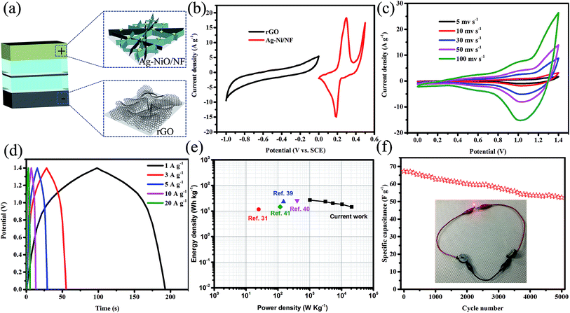
ASC devices were fabricated using the as-prepared Ag-NiO/NF and rGO as the cathode and anode electrodes, respectively. A piece of polypropylene paper was used as the separator. Both electrodes were immersed into 6 M KOH along with separator and packed into CR2032 full cell (Fig. 6a). The specific capacitance of the rGO electrode was 178 F g−1 when the current density was 1 A g−1. CV curves of Ag-NiO/NF electrodes and rGO electrodes at a scan rate of 5 mV s−1 revealed that the Ag-NiO/NF electrodes and rGO electrodes have stable potential windows of 0–0.5 V and −1–0 V, respectively (Fig. 6b). According to the equation  , the charge storage capacity of cathode and anode electrodes should be balanced to obtain a high electrochemical performance. The charge balance between the two electrodes should follow the equation q+ = q−. The stored charge is related to the specific capacitance (C), the potential windows obtained in the three-electrode measure (ΔV), and the mass of the electrodes (m), which follows the relationship q = C × ΔV × m. the NiO to rGO mass ratio was calculated by the following equation:
  . The NiO to rGO mass ratio was adjusted to be 2.8
![[thin space (1/6-em)]](https://www.rsc.org/images/entities/char_2009.gif) :
:![[thin space (1/6-em)]](https://www.rsc.org/images/entities/char_2009.gif) 1.
1.
Fig. 6c shows typical CV curves for the Ag-NiO/NF//rGO7 ASC in 6 M KOH (aq) electrolyte at various scan rates in the range from 0–1.4 V. Two redox peaks were observed, and they suggested the faradaic capacitance nature of the Ag-NiO/NF//rGO capacitor arising from the Ag-NiO/NF electrode. GCD curves at different current densities from 1 A g−1 to 20 A g−1 are shown in Fig. 6d. No obvious Ir drop was observed, suggesting a low internal resistance for the ASC. The GCD curves exhibited symmetric profiles, indicating an excellent electrochemical reversibility. The relationship between specific capacitance and current density is plotted in Fig. S2.† The calculated specific capacitances of the ASC (based on the total mass of the active materials of the two electrodes) were 97.9, 86.0, 73.4, 67.3, and 52.9 F g−1 at 1, 3, 5, 10, and 20 A g−1, respectively; therefore, the ASC presents high-rate capability.
Energy and power densities are two important parameters that can be used to evaluate the electrochemical performance of a full cell. The Ragone plot of Ag-NiO/NF//rGO ASC device based on GCD measurements is shown in Fig. 6e. A maximum energy density of 26.7 W h kg−1 was obtained at power density of 1017.1 W kg−1. The energy density was maintained at 14.4 W h kg−1 when the power density increased to 20![[thin space (1/6-em)]](https://www.rsc.org/images/entities/char_2009.gif) 869.6 W kg−1. The energy and power densities of our ASC device were superior to those of many other previously reported NiO-based ASCs, such as NiO//C (11.6 W h kg−1),31 NiO//rGO (23.25 W h kg−1),39 CNT@NiO//PCPs (25.4 W h kg−1),40 NiO//C (14.6 W h kg−1).41 Cycling performance was measured by charging and discharging the devices 3000 times at a current density 10 A g−1 (Fig. 6f). A total of 77.8% of initial capacitance of the device remained after 3000 charge/discharge cycles. The applicability could be proved visibly by powering red light-emitting diodes (LEDs). The serially connected two ASC devices lighted up the commercial LED, as displayed in the inset of Fig. 6f.
869.6 W kg−1. The energy and power densities of our ASC device were superior to those of many other previously reported NiO-based ASCs, such as NiO//C (11.6 W h kg−1),31 NiO//rGO (23.25 W h kg−1),39 CNT@NiO//PCPs (25.4 W h kg−1),40 NiO//C (14.6 W h kg−1).41 Cycling performance was measured by charging and discharging the devices 3000 times at a current density 10 A g−1 (Fig. 6f). A total of 77.8% of initial capacitance of the device remained after 3000 charge/discharge cycles. The applicability could be proved visibly by powering red light-emitting diodes (LEDs). The serially connected two ASC devices lighted up the commercial LED, as displayed in the inset of Fig. 6f.
4. Conclusions
In this study, surface loading of NiO/NF with Ag particles was prepared using a wet chemical method. NiO nanosheet arrays were grown vertically on the NF, which served as a conducting scaffold to improve the conductive nature. The anchored Ag particles further increased the electronic conductivity. The electrochemical properties of the Ag-NiO/NF electrode resulted in superior specific capacitance of 1254.9 F g−1 at 1 A g−1 over that of the NiO/NF (946.3 F g−1) at a current density of 1 A g−1. Furthermore, ASC devices were assembled with Ag-NiO/NF and rGO in 6 M KOH. The ASC device delivered a high energy density of 26.7 W h kg−1 and the power density of 20![[thin space (1/6-em)]](https://www.rsc.org/images/entities/char_2009.gif) 869.6 W kg−1 with the potential window of 1.4 V. Moreover, the assembled devices exhibited a good cycling stability with 77.8% initial capacitance retention after 3000 cycles.
869.6 W kg−1 with the potential window of 1.4 V. Moreover, the assembled devices exhibited a good cycling stability with 77.8% initial capacitance retention after 3000 cycles.
Conflicts of interest
There are no conflicts to declare.Acknowledgements
This work was supported by the Global Frontier hybrid Interface Materials (GFHIM) program of the National Research Foundation of Korea (NRF) funded by the Ministry of Science, ICT & Future Planning (2013M3A6B1078874), the Science and Technology Development Fund from Macau SAR (FDCT-098/2015/A3) and the UEA funding.References
- C. Merlet, B. Rotenberg, P. A. Madden, P. L. Taberna, P. Simon, Y. Gogotsi and M. Salanne, Nat. Mater., 2012, 11, 306–310 CrossRef CAS PubMed.
- P. Simon and Y. Gogotsi, Nat. Mater., 2008, 7, 845–854 CrossRef CAS PubMed.
- B. E. Conway, V. Birss and J. Wojtowicz, J. Power Sources, 1997, 66, 1–14 CrossRef CAS.
- Z. S. Wu, W. C. Ren, D. W. Wang, F. Li, B. L. Liu and H. M. Cheng, ACS Nano, 2010, 4, 5835–5842 CrossRef CAS PubMed.
- J. Yan, Q. Wang, T. Wei and Z. J. Fan, Adv. Energy Mater., 2014, 4, 1300816 CrossRef.
- S. X. Wu, K. S. Hui and K. N. Hui, J. Phys. Chem. C, 2015, 119, 23358–23365 CAS.
- S. X. Wu, K. S. Hui, K. N. Hui and K. H. Kim, J. Mater. Chem. A, 2016, 4, 9113–9123 CAS.
- Z. J. Gu, L. Yan, G. Tian, S. J. Li, Z. F. Chai and Y. L. Zhao, Adv. Mater., 2013, 25, 3758–3779 CrossRef CAS PubMed.
- M. J. Zhi, C. C. Xiang, J. T. Li, M. Li and N. Q. Wu, Nanoscale, 2013, 5, 72–88 RSC.
- M. Huang, F. Li, J. Y. Ji, Y. X. Zhang, X. L. Zhao and X. Gao, CrystEngComm, 2014, 16, 2878–2884 RSC.
- Y. X. Zhang, M. Kuang and J. J. Wang, CrystEngComm, 2014, 16, 492–498 RSC.
- G. H. Lee, Y. W. Cheng, C. V. Varanasi and J. Liu, J. Phys. Chem. C, 2014, 118, 2281–2286 CAS.
- G. H. Yuan, Z. H. Jiang, A. Aramata and Y. Z. Gao, Carbon, 2005, 43, 2913–2917 CrossRef CAS.
- M. Zhou, Y. F. Deng, K. Liang, X. J. Liu, B. Q. Wei and W. C. Hu, J. Electroanal. Chem., 2015, 742, 1–7 CrossRef CAS.
- J. Y. Cheng, B. Zhao, W. K. Zhang, F. Shi, G. P. Zheng, D. Q. Zhang and J. H. Yang, Adv. Funct. Mater., 2015, 25, 7381–7391 CrossRef CAS.
- S. J. Kim, G. J. Park, B. C. Kim, J. K. Chung, G. G. Wallace and S. Y. Park, Synth. Met., 2012, 161, 2641–2646 CrossRef.
- N. B. Trung, T. V. Tam, D. K. Dang, K. F. Babu, E. J. Kim, J. Kim and W. M. Choi, Chem. Eng. J., 2015, 264, 603–609 CrossRef CAS.
- H. Jiang, P. S. Lee and C. Z. Li, Energy Environ. Sci., 2013, 6, 41–53 CAS.
- C. X. Hu, S. J. He, S. H. Jiang, S. L. Chen and H. Q. Hou, RSC Adv., 2015, 5, 14441–14447 RSC.
- M. J. Deng, C. Z. Song, C. C. Wang, Y. C. Tseng, J. M. Chen and K. T. Lu, ACS Appl. Mater. Interfaces, 2015, 7, 9147–9156 CAS.
- Z. Gonzalez, A. J. Sanchez-Herencia, B. Ferrari, A. Caballero and J. Morales, Key Eng. Mater., 2015, 2016, 58–64 CrossRef.
- M. Usman, L. J. Pan, A. Sohail, Z. Mahmood and R. X. Cui, Chem. Eng. J., 2017, 311, 359–366 CrossRef CAS.
- R. Chadha, N. Maiti and S. Kapoor, Mater. Sci. Eng., C, 2014, 38, 192–196 CrossRef CAS PubMed.
- X. M. Wu, Z. Q. He, S. Chen, M. Y. Ma, Z. B. Xiao and R. Ben Liu, Mater. Lett., 2006, 60, 2497–2500 CrossRef CAS.
- M. Vanitha, Keerthi, P. Cao and N. Balasubramanian, J. Alloys Compd., 2015, 644, 534–544 CrossRef CAS.
- L. B. Ma, X. P. Shen, Z. Y. Ji, G. X. Zhu and H. Zhou, Chem. Eng. J., 2014, 252, 95–103 CrossRef CAS.
- L. Q. Mai, A. Minhas-Khan, X. C. Tian, K. M. Hercule, Y. L. Zhao, X. Lin and X. Xu, Nat. Commun., 2013, 4, 2923 Search PubMed.
- S. Nishimura, D. Mott, A. Takagaki, S. Maenosono and K. Ebitani, Phys. Chem. Chem. Phys., 2011, 13, 9335–9343 RSC.
- C. P. Chen, P. Gunawan, X. W. Lou and R. Xu, Adv. Funct. Mater., 2012, 22, 780–787 CrossRef CAS.
- W. Xing, F. Li, Z. F. Yan and G. Q. Lu, J. Power Sources, 2004, 134, 324–330 CrossRef CAS.
- D. W. Wang, F. Li and H. M. Cheng, J. Power Sources, 2008, 185, 1563–1568 CrossRef CAS.
- K. W. Nam and K. B. Kim, J. Electrochem. Soc., 2002, 149, A346–A354 CrossRef CAS.
- S. M. Chen, G. Yang, Y. Jia and H. J. Zheng, ChemElectroChem, 2016, 3, 1490–1496 CrossRef CAS.
- J. K. Gan, Y. S. Lim, N. M. Huang and H. N. Lim, RSC Adv., 2015, 5, 75442–75450 RSC.
- H. Xia, C. Y. Hong, X. Q. Shi, B. Li, G. L. Yuan, Q. F. Yao and J. P. Xie, J. Mater. Chem. A., 2015, 3, 1216–1221 CAS.
- Q. Lu, M. W. Lattanzi, Y. P. Chen, X. M. Kou, W. F. Li, X. Fan, K. M. Unruh, J. G. G. Chen and J. Q. Xiao, Angew. Chem., Int. Ed., 2011, 50, 6847–6850 CrossRef CAS PubMed.
- B. Wang, J. S. Chen, Z. Y. Wang, S. Madhavi and X. W. Lou, Adv. Energy Mater., 2012, 2, 1188–1192 CrossRef CAS.
- M. Huang, F. Li, F. Dong, Y. X. Zhang and L. L. Zhang, J. Mater. Chem. A, 2015, 3, 21380–21423 CAS.
- X. C. Ren, C. L. Guo, L. Q. Xu, T. T. Li, L. F. Hou and Y. H. Wei, ACS Appl. Mater. Interfaces, 2015, 7, 19930–19940 CAS.
- H. Yi, H. W. Wang, Y. T. Jing, T. Q. Peng and X. F. Wang, J. Power Sources, 2015, 285, 281–290 CrossRef CAS.
- G. H. Cheng, Q. G. Bai, C. H. Si, W. F. Yang, C. Q. Dong, H. Wang, Y. L. Gao and Z. H. Zhang, RSC Adv., 2015, 5, 15042–15051 RSC.
Footnote |
| † Electronic supplementary information (ESI) available. See DOI: 10.1039/c7ra06252d |
| This journal is © The Royal Society of Chemistry 2017 |

