
 Open Access Article
 This Open Access Article is licensed under a Creative Commons Attribution-Non Commercial 3.0 Unported Licence
A novel cellulose–silicalite-1 membrane with excellent gas separation property
Xin-ling Fu ,
Ming Zeng,
Jian-bo Zhou* and
Chao Xu*
,
Ming Zeng,
Jian-bo Zhou* and
Chao Xu*
Department of Anatomy, Histology and Embryology, College of Basic Medical Sciences, Changsha Medical University, Changsha, Hunan 410219, China. E-mail: fuxinling220@126.com
First published on 22nd August 2017
Abstract
A novel strategy for synthesizing silicalite-1 membrane by hydrothermal synthesis without organic template after coating the support with a mixture of modified cellulose and seeds was successfully proposed. The membrane possesses high ideal separation factors of H2 over various gases which is larger than the corresponding Knudsen diffusion coefficients. The selectivity of AcOH from AcOH/H2O mixtures can reach to 65 and stable for 180 h. The characterization results by XRD and SEM showed that the excellent performance can be attributed to both modified cellulose and the synthesis without organic template. Modified cellulose attracted more silicalite-1 nutrients to the support and assisted the synthesis of more compact silicalite-1 zeolite membrane. Calcination after synthesis was avoided, thus avoiding macrostructure defects appearing during the process of calcination.
1. Introduction
Membrane separations have made significant contributions in fuels, petrochemicals, energy, and renewable chemical sectors because of their excellent properties, such as energy efficiency, low cost and environment friendliness, compared with conventional separation methods.1 Inorganic zeolite membranes are effective in gas and liquid separations because they present some substantial advantages over conventional organic materials with respect to thermal and chemical stabilities.2,3 Recently, much study has been reported on preparation and separation application of molecular-sieve inorganic zeolite membranes.4,5 Despite great advances in zeolite membrane separation technology, particularly with respect to alcohol–water separation,6 formation of compact and thin films for gas separation is still favored.Various methods have been explored by researchers to synthesize zeolite membranes such as direct hydrothermal crystallization,7 adding seeds8,9 or organic cations,10,11 microwave heating12 and gas-phase transformation.13 The organic templates, which are required for the formation of the zeolite crystal structure, are used in most processes of synthesizing zeolite membranes. Accordingly, heat treatment after hydrothermal synthesis is a common post-treatment of zeolite membranes for removing SDAs and/or water from the zeolite pores. However, the zeolite membranes are easy to crack due to the mismatches in the thermal expansion coefficients between support and zeolite layer. While some MFI-type zeolite membranes with high performance after calcining at high temperatures have been reported,14 several studies have also shown that during the calcination process, micro cracks tend to form in the zeolite membranes due to thermal stress caused due to the difference in thermal expansion coefficients between the zeolite layer and support and/or resulting from the changes in lattice parameters of zeolite crystals as a consequence of the removal of templates.15,16 Recently, Choi et al.17 developed a rapid thermal processing (RTP) method to avoid the formation of such defects, possibly by strengthening grain bonding at the grain boundaries. While an appreciably high separation performance could be achieved, this method is complicated and expensive, which confines the practical applications. Accordingly, a new method to obtain high-performance zeolite membrane with few cracks is still a great challenge. Based on this consideration, coating a modified layer between the zeolite layer and support, which not only eliminates the grain boundary defects caused by the mismatch of thermal expansion coefficients between the support and zeolite layer but also attracts more active components to the support, and then synthesizing a zeolite layer without organic template to avoid calcination at high temperature appears to be a better approach.
In this study, a novel strategy for synthesizing silicalite-1 zeolite membrane is explored, namely, by modifying the support with modified cellulose and carrying out hydrothermal synthesis without organic template. The crystals that grow on the surfaces of the alumina supports are smooth and dense. The continuous zeolite top layer of the membrane was analyzed via scanning electron microscopy (SEM) and checked via gas permeation measurements and separation of acetic acid–water mixtures, and X-ray diffraction (XRD) was employed to examine the crystal structure of the prepared membranes. This study introduces new approaches for the improvement of separation performances of zeolite membranes in the field of membrane synthesis.
2. Experimental
2.1 Materials
All the chemicals, including tetrapropylammonium hydroxide (TPAOH) (Analytical Reagent, Aladdin), sodium hydroxide (Analytical Reagent, Guangzhou), colloidal silica solution (30 wt%, Guangzhou), dimethyl sulfoxide (DMSO) (Analytical Reagent, Guangzhou), paraformaldehyde (PF) (Analytical Reagent, Guangzhou), and α-cellulose (Analytical Reagent, Aladdin), were used as purchased without purification.2.2 Synthesis of silicalite-1 zeolite seeds
Silicalite-1 zeolite seeds were synthesized via hydrothermal heating. The solution was prepared by mixing 0.3 g sodium hydroxide, 16 g colloidal silica solution and 25 mL 1 mol L−1 TPAOH in deionized water under vigorous stirring. After aging for 12 h at 25 °C, the solution was hydrothermally treated in a Teflon lined stainless steel autoclave at 120 °C for 12 h. The seed powder obtained by centrifugation was washed with distilled water until pH 7 and dried at a temperature of 100 °C. The organic template TPAOH was removed by calcining at 450 °C for 8 h with a heating rate of 1 °C min−1. The as-obtained silicalite-1 zeolite powders, named as S1, were subjected to characterization. As a comparison, silicalite-1 zeolite powders in the market, named as S2, were also characterized.The appropriate sample was screened as the seed by characterizing the types of powders.
2.3 Preparation of seed suspension
Modified cellulose solution was prepared according to the following procedure: (1) 4 g α-cellulose and 20 g DMSO were mixed and put into a Teflon lined stainless steel autoclave at 60 °C for 30 min. (2) Opening the cover of the autoclave, 4 g PF and 20 g DMSO were added into it and the cover was closed. (3) The autoclave was put in a furnace of 120 °C for 24 h. (4) A clear liquid was obtained by centrifugation with the rotation rate of 6000 rpm twice, each time for 5 min.Moreover, 0.2 g silicalite-1 seed crystal powder was added into the modified cellulose solution and subsequently dispersed in an ultrasonic bath for 20 min. Thus, the well-dispersed silicalite-1 seeds suspension was obtained with a ratio solid/liquid = 5 g/1000 g. Moreover, the same concentration of seed suspension without cellulose was prepared by adding silicalite-1 zeolite into DMSO. Both the suspension solutions were degassed in vacuum to avoid the formation of voids between the polymer and zeolite phases resulting from the air adsorbed on the surface of the zeolite particles.
2.4 Introduction of zeolite seeds to support
A home-made porous α-A12O3 disc, with diameter of 22 mm, thickness of 1.8 mm, porosity of 65%, and average pore size of 300 nm, was used as support for the growth of zeolite membrane. The α-A12O3 disc was polished with grit-sand paper, followed by washing with 1 mol L−1 sodium hydroxide solution before using as a support. The support was dried at 110 °C after being cleaned with deionized water in an ultrasonic cleaner and subjected to the loading of silicalite-1 zeolite seeds without cooling.In order to form a homogeneous seed layer, hot dip-coating method18 was employed to deposit zeolite seeds on the surface of the support. The hot support disc was dipped in the silicalite-1 seed suspensions and maintained for 10 s to allow the seed crystals to be adsorbed on the surface and then gently slid and pulled up from the seeds suspension. Finally, it was dried at 110 °C in vacuum for 1 h. This was repeated three times to obtain a uniform distribution of seed particles on one side of the support.
2.5 Synthesis of silicalite-1 zeolite membrane
The solution for the synthesis of silicalite-1 membrane was prepared by mixing 0.74 g sodium hydroxide, 16 g colloidal silica solution and 41.5 g deionized water under vigorous stirring. The solution was boiled until it became clear and then aged for 1 day.Silicalite-1 membrane was synthesized via hydrothermal heating. The seeded support disc was first vertically immerged in the synthesis solution contained in a Teflon reactor and then the reactor was transferred into a preheated oven at 180 °C for 24 h. After cooling to room temperature, the disc was removed from the autoclave and washed with distilled water in an ultrasonic bath for 10 min. Finally, the disc was washed repeatedly by deionized water till neutral and dried first at 35 °C for 3 h and then at 100 °C overnight. The as-obtained silicalite-1 membrane was further subjected to a secondary synthesis with the same method mentioned above but reacted just for 8 h.
The membrane seeded without modified cellulose was named as M1, while the membrane seeded with modified cellulose was named as M2.
2.6 Characterization of silicalite-1 zeolite membrane
The structure of the membranes was examined via X-ray diffraction (XRD) (Bruker D8) with a scanning voltage of 40 kV, scanning current 40 Ma and scanning step 0.02°. The morphology and thickness of the silicalite-1 membranes were confirmed via scanning electron microscopy (SEM) (FEI Quanta-200) with an accelerating voltage of 20 kV. The contact angles of the silicalite-1 membranes were measured with contact angle analyzer (WCA) (DSA100).2.7 Performance of silicalite-1 membranes
The performance of silicalite-1 zeolite membrane was manifested by gas permeation and pervaporation. They were carried out over self-designed equipment, which was similar to that reported in literature.19
 | (1) |
 | (2) |
 | (3) |
3. Results and discussion
3.1 Characterization of silicalite-1 seeds
Fig. 1 shows the XRD patterns of silicalite-1 powders of S1 and S2. From the figure, one can see that the XRD patterns of both S1 and S2 are well consistent with the JCPDS file #44-0696 without diffraction peaks from other crystals, indicating a pure phase of silicalite-1 zeolite. However, the XRD peaks of S1 exhibit smaller peak intensity and larger peak width than that of S2, indicating that the crystal size of S1 is smaller than that for S2.20 In order to determine the crystal size of both S1 and S2, the corresponding SEM has been shown in Fig. 2. It is found that the morphology of S2 shows hexagonal prism type with clear edges and the corresponding average crystal size is ca. 6 μm, while S1 possesses a reduced crystal size, being determined as ca. 0.3–1 μm, with few lattice defects. It is reported that smaller crystal size and more defective surface could induce denser membrane layer.21 Accordingly, the powders of S1 have been used as the seeds for the further growth of silicalite-1 zeolite membrane.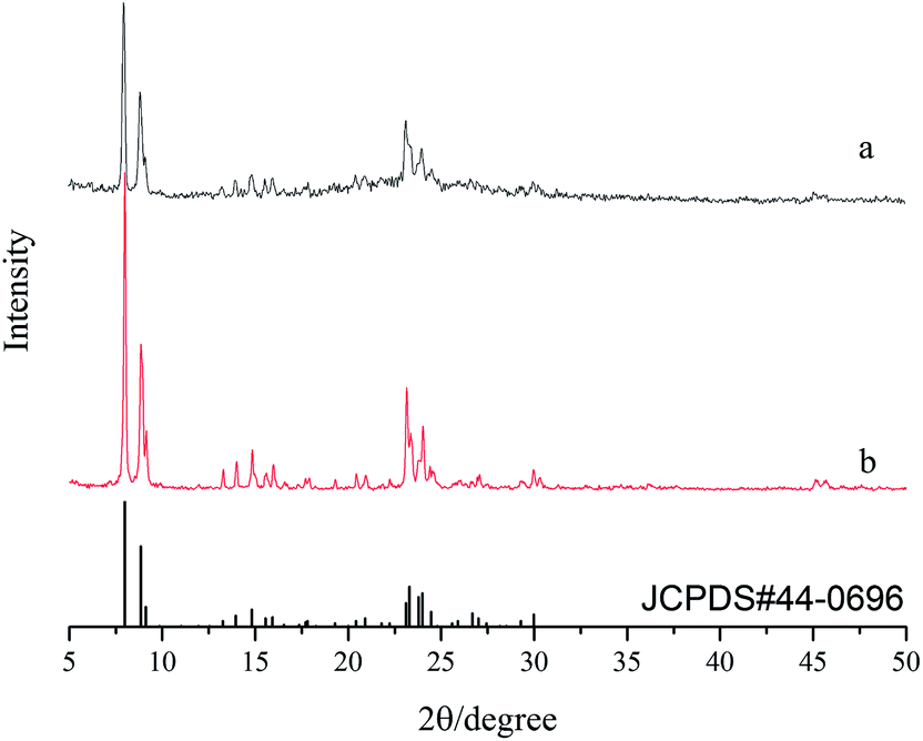 | ||
| Fig. 1 XRD patterns of (a) S1 and (b) S2. | ||
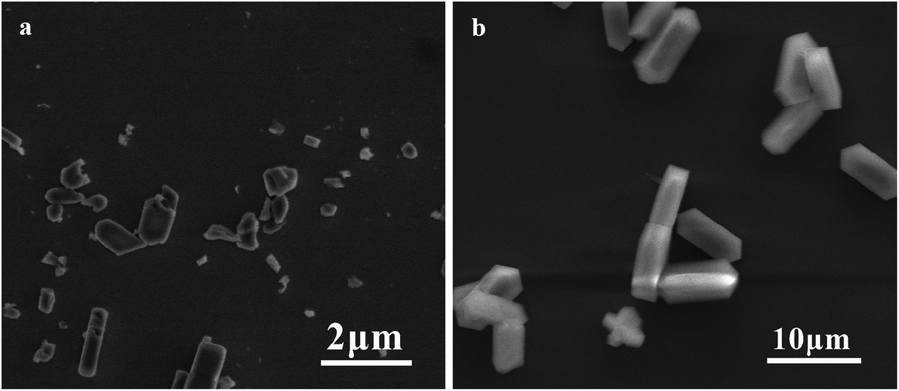 | ||
| Fig. 2 SEM micrographs of silicalite-1 powders: (a) S1 and (b) S2. | ||
3.2 Characterization of silicalite-1 zeolite membranes
Fig. 3 shows the XRD patterns of various silicalite-1 zeolite membranes. One can see that the sharp peaks at 2θ = 25.76°, 35.34°, 37.96° and 43.55° can be attributed to α-Al2O3 support, and the peak intensity for α-A12O3 decreases after zeolite membrane is synthesized. After seeding, the characteristic diffraction peaks of silicalite-1 zeolite at 2θ = 8.22°, 9.08° and 23.50° appear in the support seeded without cellulose, while in addition to silicalite-1 characteristic diffraction peaks, a broad peak from 15° to 23° also appears in the support seeded with cellulose. The broad peak can be attributed to the diffraction peak of modified cellulose, indicating that cellulose carrying the hydroxyl functional group is also uniformly dispersed on the surface of the support. After the synthesis, the peak intensity for silicalite-1 zeolite increases and that for α-A12O3 decreases. It should be addressed that the peak intensities of silicalite-1 zeolite, particularly those of the peaks at 2θ = 8.22°, 9.08° (see the circle shown in Fig. 3), are higher for M2 membrane than that for M1 membrane, indicating that the silicalite-1 zeolite layer is thicker or compacter over the former membrane relative to the latter membrane.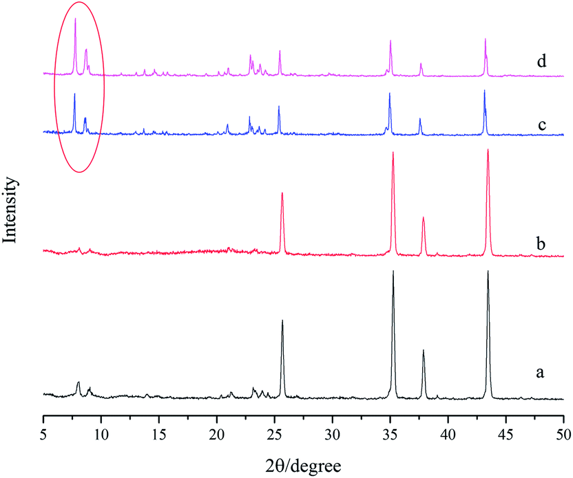 | ||
| Fig. 3 XRD patterns of (a) seed layer without modified cellulose; (b) seed layer with modified cellulose; (c) M1 membrane and (d) M2 membrane. | ||
Fig. 4 shows the SEM micrographs of various silicalite-1 zeolite membranes. From the top view of the micrographs (Fig. 4a and c), one can see that the coffin-shape grains of silicalite-1 crystals gather together over the support and construct a continuous zeolite layer for all the membranes. However, the crystal particles randomly deposit on the support and numerous defects are formed between zeolite grains in M1 membrane. As a striking contrast, the crystals deposit on the support existing in the form of twins and no significant defect can be identified in M2 membrane. The cross sectional view of the micrographs (Fig. 4b and d) show that a silicalite-1 zeolite layer has tightly grown over the support without any evident pinholes. However, the thickness of the zeolite layer is thicker for M2 membrane than that for M1 membrane, being identified as 5 μm and 2.8 μm, respectively. These results are consistent with the results of XRD. Fig. 5 shows the apparent contact angles of silicalite-1 zeolite membrane. One can see that, α-A12O3 support is completely hydrophilic and the corresponding contact angle is approximately 0°. After the hydrothermal synthesis, the contact angle increases. The contact angle of M1 membrane is 43°, while that of M2 membrane is 61°.
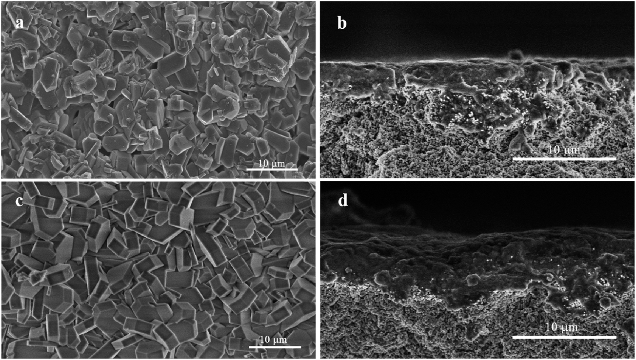 | ||
| Fig. 4 SEM micrographs of silicalite-1 zeolite membranes. (a) and (c), top view for M1 and M2 membranes, respectively; (b) and (d), cross-sectional view for M1 and M2 membranes, respectively. | ||
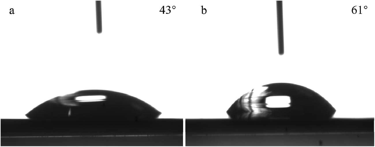 | ||
| Fig. 5 The apparent contact angles of silicalite-1 zeolite membranes. (a) M1 membrane; (b) M2 membrane. | ||
The above mentioned results can be attributed to the fact that the modified cellulose layer is between the support and zeolite layer. In DMSO solvent, PF reacts with cellulose to produce cell–O–CH2–OH,22 making more –OH group exposed to the solution, and when the support, which is coated with modified cellulose, is in contact with the synthetic solution, hydrogen bond is formed between –OH groups of modified cellulose and silanol groups of the precursor macromolecules of silicalite-1. Due to those high efficient molecular links between cellulose and silicalite-1 nutrients, more silicalite-1 nutrients are adsorbed on the surface of the support and easily grow to a dense and continuous silicalite-1 zeolite membrane. Moreover, there is no templating agent in the process of synthesizing the silicalite-1 zeolite membrane, thus avoiding the destruction of the zeolite layer during the calcination process. It should be addressed that silicalite-1 zeolite membranes have a certain hydrophobicity and the hydrophobicity becomes stronger when the zeolite membrane is denser.
3.3 Performance of silicalite-1 membranes
The performance of various small molecule gases through M1 and M2 membranes are shown in Fig. 6. One can see that the permeations of various gases through M1 membrane are higher than that for M2 membrane, but the permeances are at a level of 10−7 to 10−6 mol m−2 s−1 Pa−1. Both membranes show that gases with smaller kinetic diameter, except for CO2, have higher permeation flux, and the permeance of H2 is the highest. The lower permeation flux of CO2 can be due to the fact that CO2 is more condensed and adsorbed in the pores of zeolite.23 The ideal separation factors of H2 over various gases through both M1 and M2 membrane are shown in the upper right corner of Fig. 6. The ideal separators of H2 over various gases through M2 membrane are higher than that for the corresponding Knudsen diffusion coefficients, even higher than that through M1 membrane, which are determined as 5.10, 4.24, 4.25, 4.27 and 5.55 for α(H2/CO2), α(H2/N2), α(H2/CO), α(H2/CH4) and α(H2/C3H8), respectively. This occurrence can be due to the compactness of the zeolite membrane. M1 membrane is thin with numerous defects in macroporous structures; and hence it is easy for all the gases to pass through the membrane with low selectivity. In comparison, M2 membrane is denser with few defects, and the gases pass through the membrane from the pores of zeolite. The gas with small kinetic diameter will be preferred through the pores of the zeolite, while the gas with larger kinetic diameter will be blocked by the membrane. Accordingly, M2 membrane shows higher selectivity than M1 membrane and the corresponding Knudsen diffusion coefficients.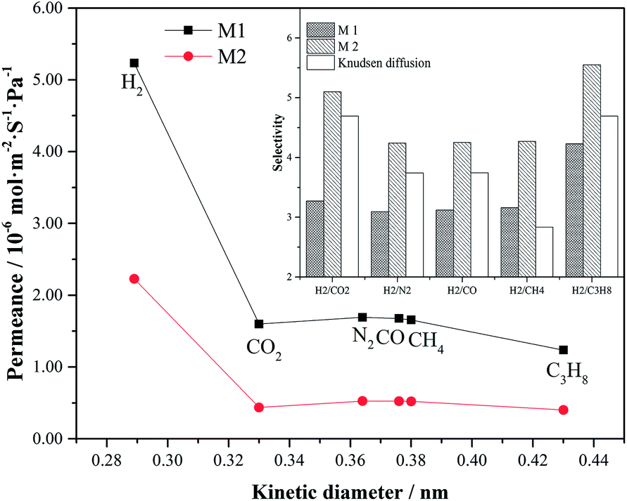 | ||
| Fig. 6 Performance of various small molecule gases through M1 and M2 membranes at 298 K and under 0.1 MPa pressure difference. | ||
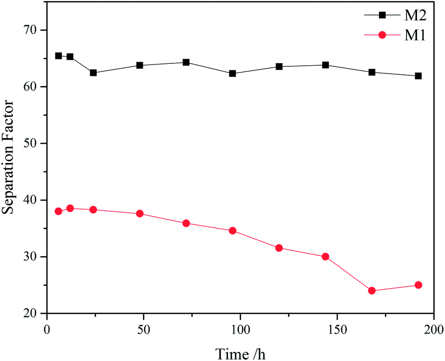
Silicalite-1 membrane is a hydrophobic zeolite membrane (see Fig. 5). When organic aqueous solutions are fed in the membrane, organics are preferably adsorbed on the surface of zeolite membrane and passed through the pores of zeolite. Accordingly, silicalite-1 membrane has a good separation effect on acetic acid aqueous solution. Fig. 7 shows AcOH/H2O separation factors of M1 and M2 membranes at 70 °C and under 0.4 MPa pressure difference. One can see that M2 membrane exhibits higher selectivity towards water separation than M1 membrane, and the separation factor of AcOH over water through M2 membrane can reach up to 65. Moreover, M2 membrane still remains highly stable after 180 h, while the separation factor of M1 membrane begins to drop linearly after 50 h. Furthermore, Fig. 8 shows SEM micrographs of silicalite-1 zeolite membranes after treating with AcOH/H2O mixture for 180 h. One can see that both M1 and M2 membranes are still covered with coffin-shaped grains of silicalite-1 crystals. However, the edges of the crystals are blurred and a large number of holes appear on the surface of M1 membrane. This result is because there is no calcination, and some amount of silanol group on the surface of zeolite membrane is retained. Those silanol groups form a dense network via hydrogen bond and few silanol groups are exposed to the outside of the membrane. Therefore, water molecules are difficult to adsorb on the surface of the zeolite membrane, while AcOH molecules are preferentially adsorbed on it. M2 membrane with dense silicalite-1 zeolite layer has complete silanol group network compared to M1 membrane, and thus exhibits higher selectivity for AcOH/H2O. At the same time, M1 membrane has a lot of defects, resulting in a part of silicon in the amorphous form. These amorphous silicon components are dissolved under acidic conditions, decreasing the selectivity of M1 membrane when used for a long time.
 | ||
| Fig. 7 AcOH/H2O separation factors of M1 and M2 membranes at 70 °C and under 0.4 MPa pressure difference. | ||
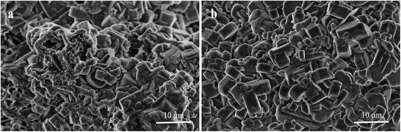 | ||
| Fig. 8 SEM micrographs of silicalite-1 zeolite membranes after treating with AcOH/H2O mixture for 180 h. (a) Top view for M1 membrane; (b) top view for M2 membrane. | ||
4. Conclusion
In summary, M2 membrane synthesized by hydrothermal synthesis without organic template after support being coated with a mixture of modified cellulose and seed crystals possesses high ideal separation factors of H2 over various gases, being larger than the corresponding Knudsen diffusion coefficients. Moreover, this membrane exhibits higher selectivity for AcOH from AcOH/H2O mixtures, relative to M1 membrane. The excellent performance can be attributed to both modified cellulose and the synthesis without organic template. Modified cellulose attracts more of silicalite-1 nutrients to the support and assists to synthesize more compact silicalite-1 zeolite membrane. No organic template is added during the synthesis process to avoid the calcination after synthesis, thus avoiding macrostructure defects appearing during the calcination process. This study opens a new way to the synthesis of high performance zeolite membranes in the field of separation.Conflicts of interest
There are no conflicts to declare.Acknowledgements
This study has been supported by the construct program of the key discipline in Hunan province and the Scientific research projects of the education department of Hunan Province (15C0144).References
- R. W. Baker, E. L. Cussler, W. Eykamp, W. J. Koros, R. L. Riley and H. Strathmann, in Membrane separation systems – a research and development needs assessment, 1990, pp. Medium: ED Search PubMed
.
- G. E. Romanos, T. A. Steriotis, E. S. Kikkinides, N. K. Kanellopoulos, V. Kasselouri, J. D. F. Ramsay, P. Langlois and S. Kallus, Innovative methods for preparation and testing of Al2O3 supported silicalite-1 membranes, J. Eur. Ceram. Soc., 2001, 21, 119–126 CrossRef CAS
- Y. Yan, M. E. Davis and G. R. Gavalas, Preparation of highly selective zeolite ZSM-5 membranes by a post-synthetic coking treatment, J. Membr. Sci., 1997, 123, 95–103 CrossRef CAS
- M. Govindan, B. Zhu, M. Duke, S. Gray and I. S. Moon, Co3+ homogeneous mediator generation efficiency in a divided tubular electrochemical reactor with MFI-type zeolite membrane, J. Ind. Eng. Chem., 2017, 52, 28–34 CrossRef CAS
- N. Itoh, J. Ishida, T. Sato and Y. Hasegawa, Vapor phase esterification using a CHA type of zeolite membrane, Catal. Today, 2016, 268, 79–84 CrossRef CAS
- Y. Morigami, M. Kondo, J. Abe, H. Kita and K. Okamoto, The first large-scale pervaporation plant using tubular-type module with zeolite NaA membrane, Sep. Purif. Technol., 2001, 25, 251–260 CrossRef CAS
- H. Li, J. Xu, J. Wang, J. Yang, K. Bai, J. Lu, Y. Zhang and D. Yin, Seed-free synthesis of highly permeable zeolite NaA membranes through deposition of APTES-functionalized alumina particles on macroporous supports, J. Membr. Sci., 2014, 471, 84–93 CrossRef CAS
- J. Shao, Z. Y. Zhan, J. G. Li, Z. B. Wang, K. Li and Y. S. Yan, Zeolite NaA membranes supported on alumina hollow fibers: effect of support resistances on pervaporation performance, J. Membr. Sci., 2014, 451, 10–17 CrossRef CAS
- M. Moheb Shahrestani, A. Moheb and M. Ghiaci, High performance dehydration of ethyl acetate/water mixture by pervaporation using NaA zeolite membrane synthesized by vacuum seeding method, Vacuum, 2013, 92, 70–76 CrossRef CAS
- A. Huang and J. R. Caro, Cationic Polymer Used to Capture Zeolite Precursor Particles for the Facile Synthesis of Oriented Zeolite LTA Molecular Sieve Membrane, Chem. Mater., 2010, 22, 4353–4355 CrossRef CAS
- K. P. Dey, D. Kundu, M. Chatterjee, M. K. Naskar and W. Suchanek, Preparation of NaA Zeolite Membranes Using Poly(Ethyleneimine) as Buffer Layer, and Study of Their Permeation Behavior, J. Am. Ceram. Soc., 2013, 96, 68–72 CrossRef CAS
- D. Kunnakorn, T. Rirksomboon, P. Aungkavattana, N. Kuanchertchoo, D. Atong, S. Kulprathipanja and S. Wongkasemjit, Performance of sodium A zeolite membranes synthesized via microwave and autoclave techniques for water–ethanol separation: recycle-continuous pervaporation process, Desalination, 2011, 269, 78–83 CrossRef CAS
- Z. L. Cheng, Z. S. Chao, H. Q. Lin and H. L. Wan, NaA zeolite membrane with high performance synthesized by vapor phase transformation method, Chin. J. Chem., 2003, 21, 1430–1432 CrossRef CAS
- J. Hedlund, J. Sterte, M. Anthonis, A.-J. Bons, B. Carstensen, N. Corcoran, D. Cox, H. Deckman, W. De Gijnst, P.-P. de Moor, F. Lai, J. McHenry, W. Mortier, J. Reinoso and J. Peters, High-flux MFI membranes, Microporous Mesoporous Mater., 2002, 52, 179–189 CrossRef CAS
- M. J. den Exter, H. van Bekkum, C. J. M. Rijn, F. Kapteijn, J. A. Moulijn, H. Schellevis and C. I. N. Beenakker, Stability of Oriented Silicalite-1 Films in View of Zeolite Membrane Preparation, Zeolites, 1997, 19, 13–20 CrossRef CAS
- J. Dong, Y. S. Lin, M. Z. C. Hu, R. A. Peascoe and E. A. Payzant, Template-removal-associated microstructural development of porous-ceramic-supported MFI zeolite membranes, Microporous Mesoporous Mater., 2000, 34, 241–253 CrossRef CAS
- J. Choi, H.-K. Jeong, M. A. Snyder, J. A. Stoeger, R. I. Masel and M. Tsapatsis, Grain boundary defect elimination in a zeolite membrane by rapid thermal processing, Science, 2009, 325, 590–593 CrossRef CAS PubMed
- X.-L. Wei, S. Liang, Y.-Y. Xu, Y.-L. Sun, J.-F. An and Z.-S. Chao, Methylcellulose-assisted synthesis of a compact and thin NaA zeolite membrane, RSC Adv., 2016, 6, 71863–71866 RSC
- X.-L. Wei, S. Liang, Y.-Y. Xu, Y.-L. Sun, J.-F. An and Z.-S. Chao, Patching NaA zeolite membrane by adding methylcellulose into the synthesis gel, J. Membr. Sci., 2017, 530, 240–249 CrossRef CAS
- B. Adnadjević, J. Vukićević, Z. Filipović-Rojka and V. Marković, The influence of NaX zeolite particle size on crystallinity measured by the XRD method, Zeolites, 1990, 10, 699–702 CrossRef
- Z. Yang, Y. Liu, C. Yu, X. Gu and N. Xu, Ball-milled NaA zeolite seeds with submicron size for growth of NaA zeolite membranes, J. Membr. Sci., 2012, 392–393, 18–28 CrossRef CAS
- D. C. Johnson, M. D. Nicholson and F. C. Haigh, Dimethyl sulfoxide/paraformaldehyde: a nondegrading solvent for cellulose, Eighth Cellulose Conference at Syracuse, New York, May 1975 Search PubMed.
- Y. S. Lin, I. Kumakiri, B. N. Nair and H. Alsyouri, Microporous Inorganic Membranes, Sep. Purif. Rev., 2007, 31, 229–379 CrossRef
| This journal is © The Royal Society of Chemistry 2017 |