
 Open Access Article
 This Open Access Article is licensed under a
 Creative Commons Attribution 3.0 Unported Licence
Giant Pockels effect of polar organic solvents and water in the electric double layer on a transparent electrode
Hironori Kanemarua,
Shunpei Yukitaa,
Hajime Namikia,
Yugo Nosakaa,
Takayoshi Kobayashibc and
Eiji Tokunaga *ad
*ad
aDepartment of Physics, Faculty of Science, Tokyo University of Science, 1-3 Kagurazaka, Shinjuku-ku, Tokyo 162-8601, Japan. E-mail: eiji@rs.kagu.tus.ac.jp
bAdvanced Ultrafast Laser Research Center, Brain Science Inspired Life Support Research Center, The University of Electro-Communications, 1-5-1 Chofugaoka, Chofu, Tokyo 182-8585, Japan
cAdvanced Ultrafast Laser Research Center, Department of Electrophysics, National Chiao-Tung University, 1001 Ta Hsinchu Rd., Hsinchu 300, Taiwan
dResearch Center for Water Frontier Science and Technology, Tokyo University of Science, 1-3 Kagurazaka, Shinjuku-ku, Tokyo 162-8601, Japan
First published on 25th September 2017
Abstract
The Pockels effect of polar organic solvents and water within the electric double layer (EDL) on an indium–tin–oxide (ITO) electrode is studied to find that water has the largest Pockels coefficient (230 pm V−1), followed in order by methanol (200 pm V−1), ethanol (84 pm V−1), and dimethyl sulfoxide (DMSO) (20 pm V−1). Electrolyte solutions of water and methanol have nearly the same magnitude of Pockels coefficient, while ethanol and DMSO solutions exhibit two and ten times smaller Pockels coefficients than the methanol solution, respectively. The Pockels coefficient scales well with the hydrogen-bond strength (or average cluster size) divided by the solvent viscosity. This suggests that hydrogen bonding and viscosity play crucial roles in the mechanism of the Pockels effect of these liquids.
I. Introduction
The linear electro-optic (EO) effect, or Pockels effect, exists only in crystals that do not possess inversion symmetry.1 Therefore it is usually ruled out to use bulk liquid, where constituent molecules are randomly oriented to keep macroscopic centrosymmetry, as an EO device. Recently, the EO effect of water within the electric double layer (EDL) at the electrode–solution interface2,3 was reported to have a Pockels constant one order of magnitude larger than that in typical electro-optic crystals such as LiNbO3.1,4,5 The thickness of the EDL defined by the Debye–Hückel length2 is estimated to be of the nanoscale-order. There is also an intriguing report of the Pockels effect even in a bulk water region between the electrodes.6,7 Recently, the Pockels effect was observed at the air–water interface, too.8 Then, there arise natural questions: whether water is a special liquid in that it possesses a large Pockels coefficient? Do other liquids such as organic solvents also have large Pockels coefficients?The principle for the Pockels effect of water to occur is the initially induced broken centrosymmetry due to the presence of the electrode surface even without an applied electric field, but a microscopic physical mechanism to predict the size of the Pockels effect is yet to be clarified. From the theoretical side, this is probably because the electronic structure needs to be modelled precisely in order to predict the dynamic polarizability of the interfacial water,9 but it is difficult to conduct ab initio calculations of both the molecular and electronic structures of electrolyte dissolved liquid water at the liquid–solid interface in the presence of an electric field.10 Recent advances in computational methodology for simulating nonlinear optical properties realize rigorous calculation of the dynamic electronic hyper-polarizability of crystalline systems and surfaces to reproduce experimental data.11 Thus there is an expectation that the Pockels effect of water is a potentially solvable problem computationally. From the experimental side, there is insufficient information about which properties of water play crucial roles. The electrode surface can induce orientational ordering of water12 or the interaction of water molecules with the atoms of the electrode surface.3,13,16 Orientational ordering of water molecules in the EDL is a possible mechanism, but the principal dynamic polarizability of the water molecules has been reported to be nearly isotropic both experimentally14 and theoretically.15 Thus, a hydrogen-bond network of water or the interaction of water molecules with the surface atoms of the electrode were suggested to be mechanisms.4,5 It is therefore interesting to investigate whether the large Pockels effect is specific to liquid water, or is common to other liquids such as organic solvents.
Water is a special liquid because of its strong hydrogen bonding network.17–21 Thus, the relevance of the hydrogen bond22 to the Pockels effect is of great interest. In this paper therefore, we have studied the Pockels effect of three protonic solvents (water, methanol, and ethanol) and one aprotonic solvent (dimethyl sulfoxide, DMSO). Here, polar solvents are chosen because electrolytes need to be dissolved to form the EDL on the electrode for the Pockels effect to occur, as evidenced by the fact that the magnitude of the Pockels effect is proportional to the square root of the ionic strength.5 We have found that methanol and ethanol show a Pockels effect comparable to that for water while DMSO shows a much smaller effect. This is the first observation of the Pockels effect of organic solvents to the best of our knowledge.
The EDL provides a range of various electrochemical reactions at the solid–solution interface. Electrochemistry in nonaqueous solutions23,24 is increasing in its importance due to demand in practical applications such as batteries, capacitors, and display devices, and such processes as electrolytic refining, synthesis and polymerization. The applicability of ionic liquids and supercritical fluids further expands this rich field. Compared with relevant studies on water however, fundamental studies on the molecular and electronic structure of nonaqueous solutions at the electrode–solution interface are left behind these applied studies. This paper aims to approach such fundamental aspects of nonaqueous solutions using nonlinear optical investigation.
II. Experimental
Fig. 1 shows the molecular structures of the polar solvents studied. Three representative protonic solvents, water (H2O), methanol (MeOH), and ethanol (EtOH), and one aprotonic solvent, dimethyl sulfoxide (DMSO), were studied. As electrodes, indium–tin–oxide (ITO, In2O3 doped with SnO2) thin films on glass substrates (Geomatec) were used. ITO is an n-type semiconductor and is transparent in the visible region. Its thickness, resistivity, and carrier density are 330 nm, 1.2 × 10⁻⁴ Ω cm, and 1.0 × 1021 cm−3, respectively.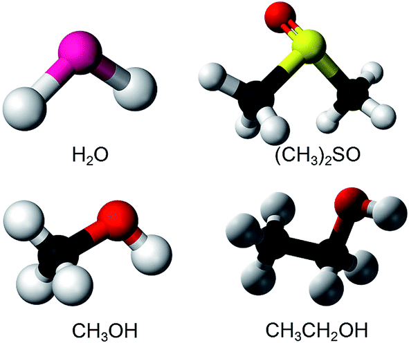 | ||
| Fig. 1 The molecular structures of the polar solvents studied: water (H2O), dimethyl sulfoxide (DMSO, (CH3)2SO), methanol (MeOH, CH3OH), and ethanol (EtOH, C2H5OH). | ||
Measurements were carried out using electromodulation spectroscopy. Fig. 2 shows a schematic of the experimental setup. Detailed descriptions of the experimental method are given in ref. 4, 5 and 16. Two ITO electrodes were immersed in 0.1 M NaCl aqueous solution or 0.1 M LiCl organic solution. In order for light to be transmitted through only one electrode, two ITO electrodes of about 5 mm × 10 mm were mutually perpendicularly oriented to be overlapped at their ends with the ITO surfaces facing each other and separated by a 0.4 cm thick glass spacer. An AC voltage of 2 V (peak amplitude, 4 Vp–p) was applied between the electrodes at a frequency f = 20 Hz, then the optical constants of the solution changed in the interface between the solution and the electrodes, i.e., in the EDL of the solution and in the space charge layer (SCL) on the surface of the ITO. The probe light from a Xe lamp, whose spatial coherence was enhanced with a pinhole of 0.4 mm, was transmitted normally through one electrode placed at a loosely focused beam position of ca. 3 mm in diameter. The other ground electrode should show the same size signal with a reversed sign due to the inverse applied voltage. If the probe light is transmitted through both electrodes, the signals cancel resulting in a null signal except in the case of some imbalance between either the geometries of the two electrodes or the sizes of the positive and negative bias signals. The electric-field-induced change in the transmittance was modulated at the AC frequency of f to be detected with a 128-channel lock-in amplifier. The transmitted probe light was focused onto a cross-sectional diameter of 0.5 mm on the input end of a multimode-fiber bundle connected to a monochromator. For collimating and focusing, quartz lenses with transmittance >90% in the 300–1000 nm range were used. All of the measurements were performed at room temperature. Since NaCl and KCl are insoluble in organic solvents, LiCl is used as an electrolyte for all of the solvents except for water. Differences of the effects among the electrolytes are described in the Appendix.
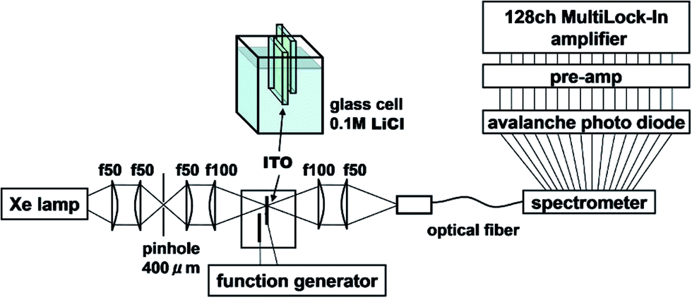 | ||
| Fig. 2 Experimental setup. | ||
For impedance measurements of the solution–electrode system, a potentiostat with an impedance analyzer (Model-1260A, Solartron) and a galvanostat (Model-1287A, Solartron) were used to make a Cole–Cole plot for the system under experimental conditions as close to those in the electromodulation measurements as possible.
III. Results
Fig. 3 shows the transmission spectrum of the ITO electrodes in air. The interference fringes are caused by the 330 nm-thick ITO layer. The decrease in the transmissivity in the UV region is due to absorption above the bandgap energy of ITO. Fig. 4 shows the normalized difference transmission spectrum ΔT/T at normal incidence. The AC voltage and the modulation frequency were 2 V (peak amplitude) and 20 Hz, respectively. There is a sharp increase in ΔT/T in the UV region, while there are interference fringes in the pattern of ΔT/T from the visible to near-IR regions.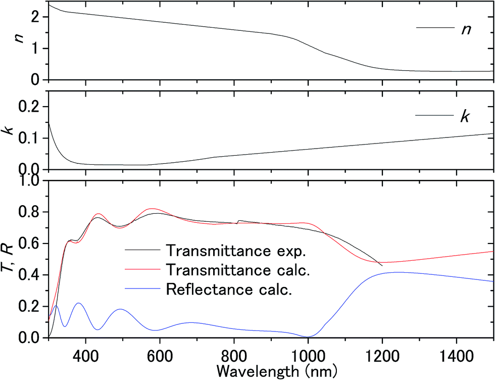 | ||
| Fig. 3 Transmittance of the ITO substrate in air and the complex refractive index fitted to the experimental transmittance. | ||
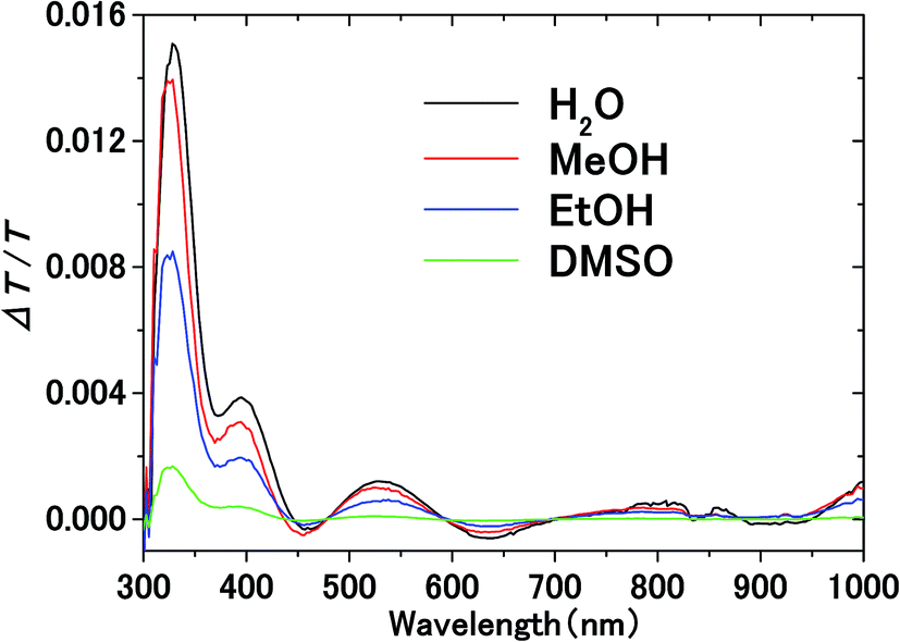 | ||
| Fig. 4 Electromodulation spectra of solvents on the ITO electrode. AC voltage at frequency f is applied between the electrodes in electrolyte solution. | ||
IV. Analyses
A. Origin of difference transmittance
The transmittance change in the visible to near-IR region is considered to be due to the change in the refractive index of the solution. However, there is also a possible contribution from the refractive index change of the ITO due to the band population effect.25,26 Fig. 5 shows the band structure of an n-type semiconductor. The band structure near the interface bends to form a SCL with the voltage applied. As a result, the absorption edge shifts to the blue (red) side for the positive (negative) bias, leading to a sharp decrease in the absorbance in the UV region. This phenomenon explains the sharp transmission increase in the UV region. The resulting change in the complex refractive index nc in the SCL of ITO was evaluated using the Lorentz model, where the imaginary part of Δnc was determined to reproduce the observed net difference transmission change in the UV. In the Lorentz model, the real and imaginary parts of Δnc are related through the Kramers–Kronig relations. Fig. 6 shows the assumed complex refractive index change in the SCL in the ITO and the refractive index change in the EDL of the electrolyte solution.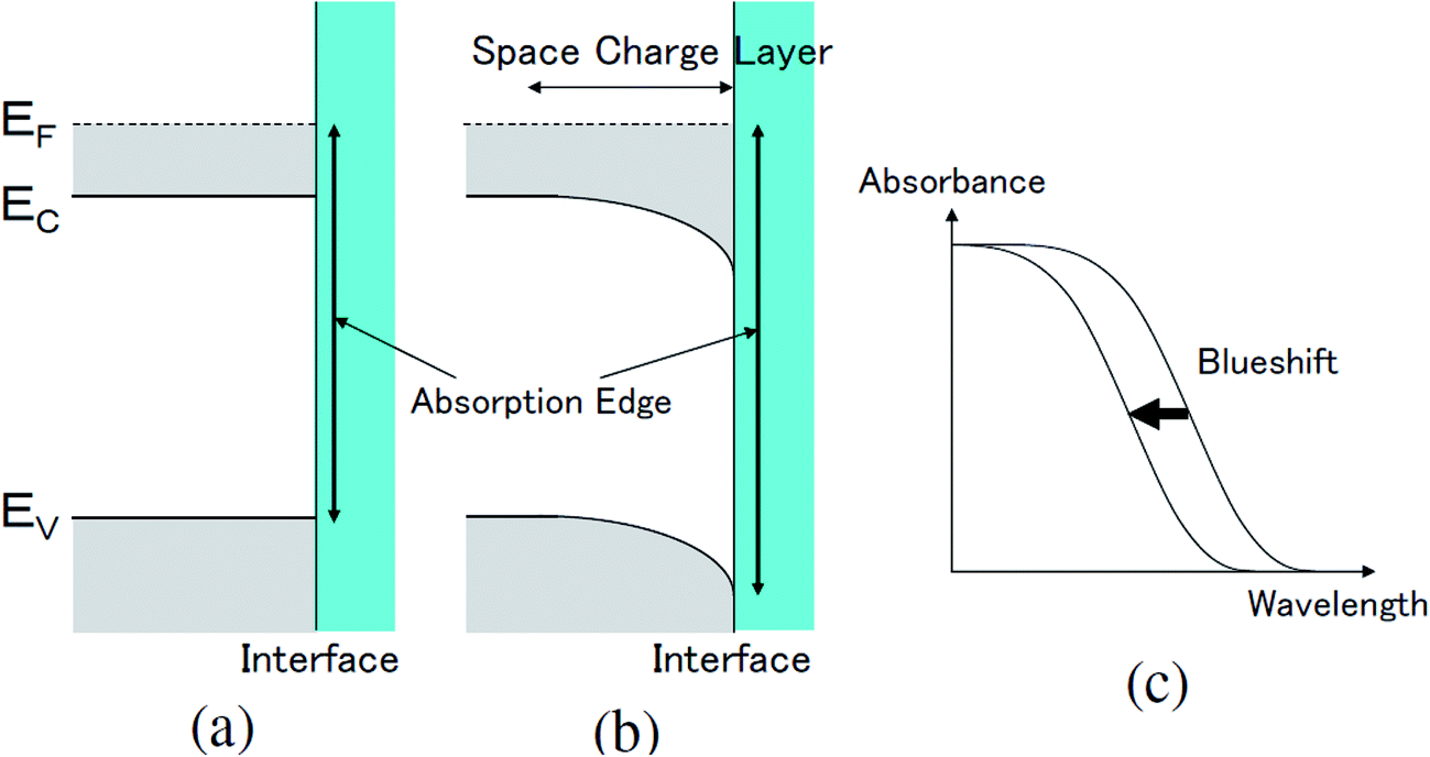 | ||
| Fig. 5 The change in the band structure near the surface in an n-type semiconductor caused by the band population effect (a) before and (b) after the application of a positive voltage to the surface, resulting in (c) the blueshift of the absorption edge. Ec, Ev, and EF are the lowest energy in the conduction band, the highest energy in the valence band, and the Fermi energy, respectively. | ||
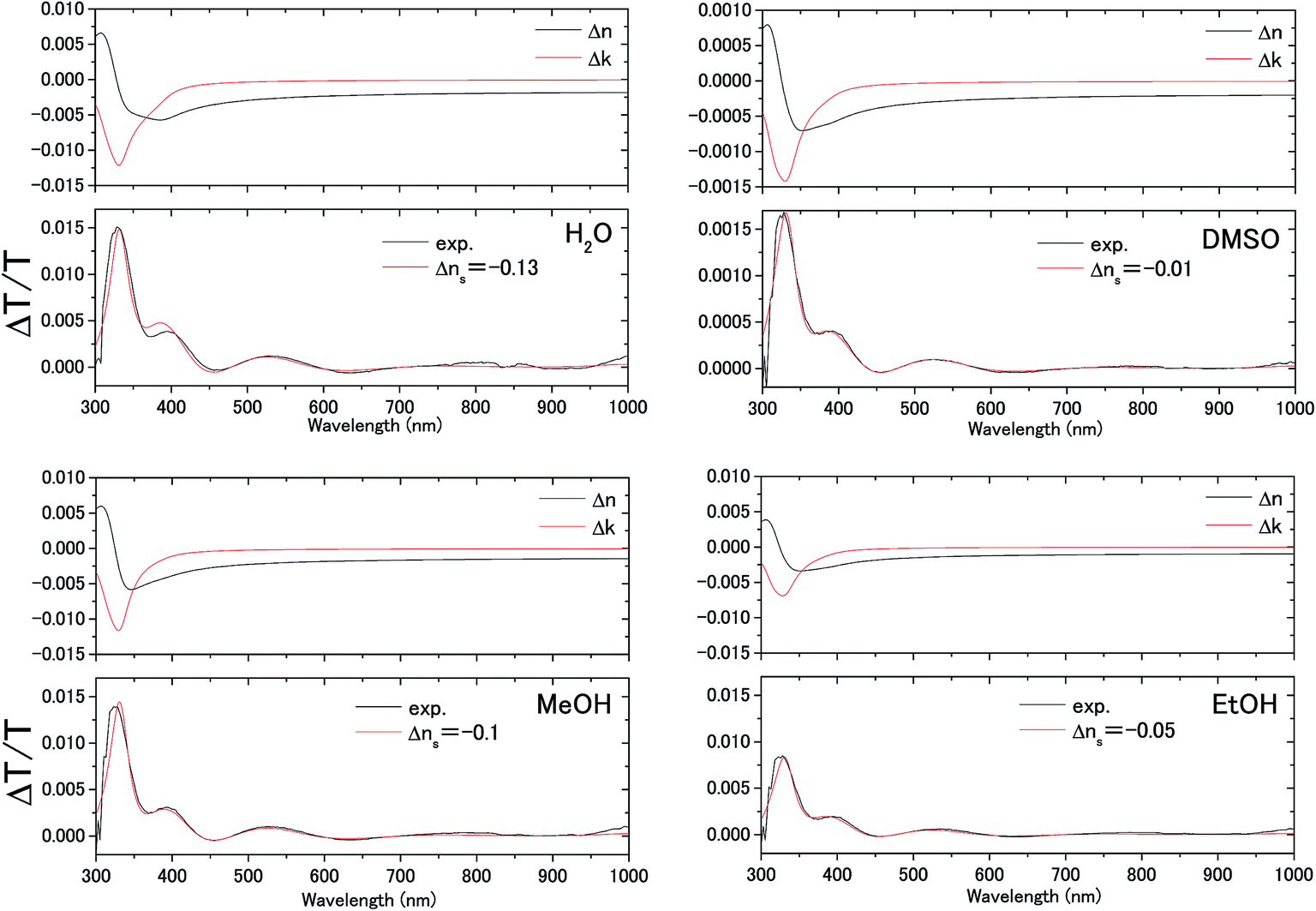 | ||
| Fig. 6 Measured electromodulation spectra (black lines) and fitted spectra (red lines) with the complex refractive index change Δn + iΔk in the space charge layer of the ITO electrode shown above and the constant refractive index change Δns in the electric double layer of the solution. | ||
The difference transmittance was then calculated using the transfer matrix method.27,28 The characteristic matrix of each layer was calculated with the optical constants of each layer, and that of all of the layers was readily obtained from the product of them. The solution–electrode interface was assumed to be a multilayer system with a constant refractive index for each layer, as shown in Fig. 7. The system structure before voltage application was modeled with a three-layer composition of solution, ITO layer, and substrate. After the voltage was applied, it was modelled with a five-layer structure composed of bulk solution, EDL, SCL, bulk ITO layer, and substrate. As mentioned above, it was assumed that the refractive index change is uniform in each layer. The red solid curves in Fig. 6 show the results calculated with the complex refractive index change in the SCL of ITO and the refractive index change Δns in the EDL of the solutions. Δns for H2O, MeOH, EtOH, and DMSO is −0.13, −0.1, −0.05, and −0.01, respectively.
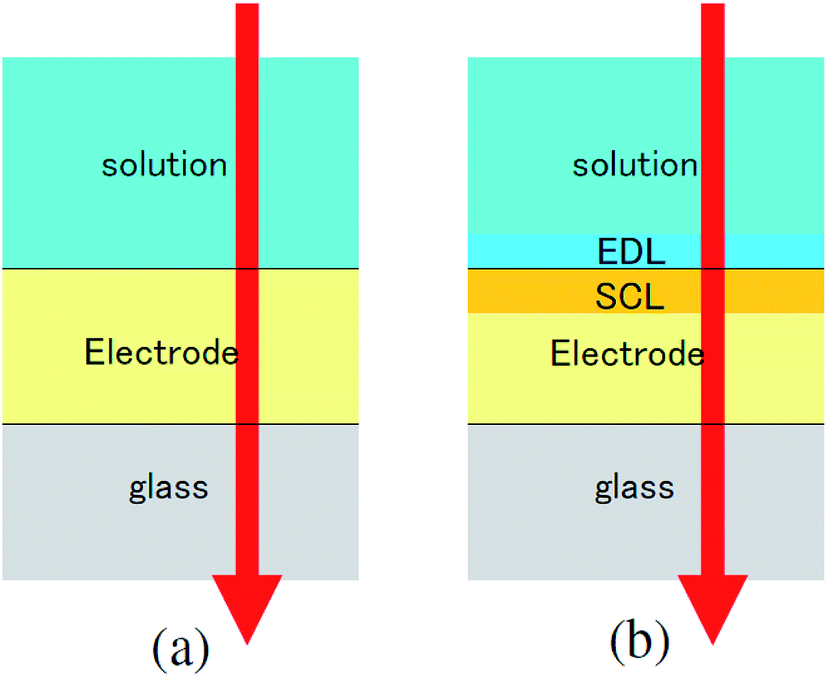 | ||
| Fig. 7 Model of the interfacial layer: (a) three-layer and (b) five-layer structure before and after the voltage was applied, respectively. | ||
B. Voltage drop at interface
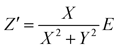
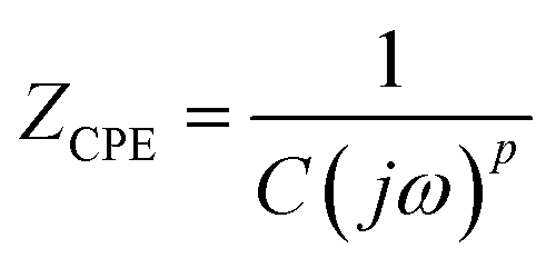
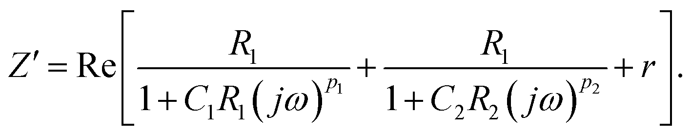
To determine the Pockels constant, the electric field in the EDL should be estimated. The voltage drops in the interfacial layers were analyzed using the impedance measurements. The geometrical positions of the electrodes in the cell and the concentration of LiCl were the same as those in Fig. 2. The impedance of the solution–electrode system is calculated using the formula:
 | (1) |
 | (2) |
 | (3) |
 , ω = 2πf where f is the frequency of the applied AC voltage, and p is a parameter for the surface roughness. Then, the impedance of the equivalent circuit is given by
 | (4) |
 | (5) |
![[thin space (1/6-em)]](https://www.rsc.org/images/entities/char_2009.gif) :SCL = 0.85:0.15 by measuring the frequency dependence of the ΔT/T signal which is contributed to solely from the SCL in ITO and from the EDL in water as shown in Fig. 10.5 Following this result, the voltage drop is concluded to be larger for the EDL than for the SCL. The ratios of the applied voltage at 20 Hz are summarized in Table 1.
:SCL = 0.85:0.15 by measuring the frequency dependence of the ΔT/T signal which is contributed to solely from the SCL in ITO and from the EDL in water as shown in Fig. 10.5 Following this result, the voltage drop is concluded to be larger for the EDL than for the SCL. The ratios of the applied voltage at 20 Hz are summarized in Table 1.
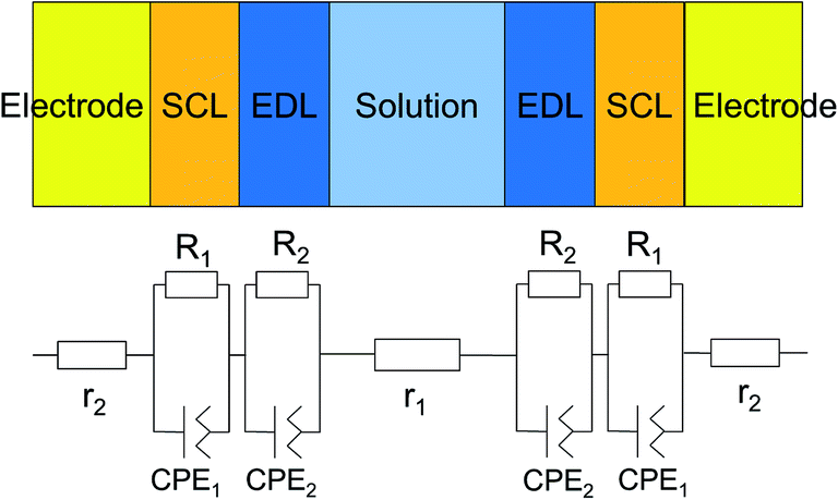 | ||
| Fig. 8 Equivalent circuit for the measured system, which consists of interfacial layers, the bulk electrode, and the bulk solution. Since the two electrodes are equivalent, the circuit parameters are the same. | ||
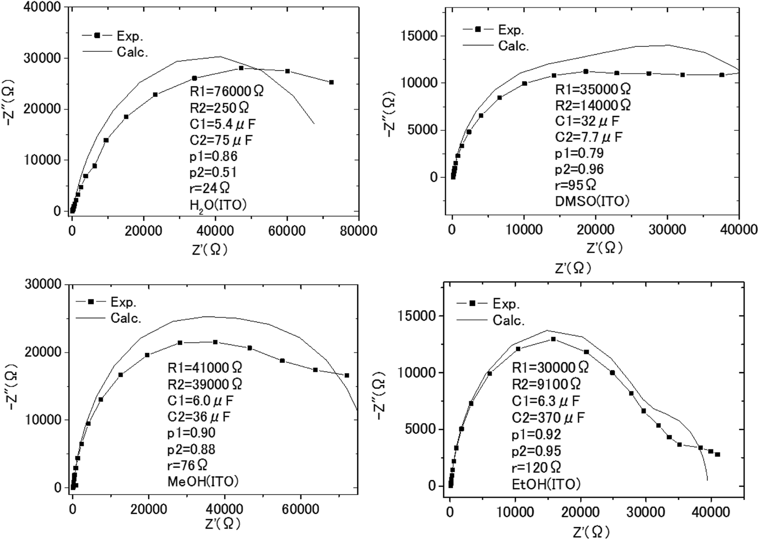 | ||
| Fig. 9 The Cole–Cole plots obtained with the impedance measurements of the solution–electrode systems. | ||
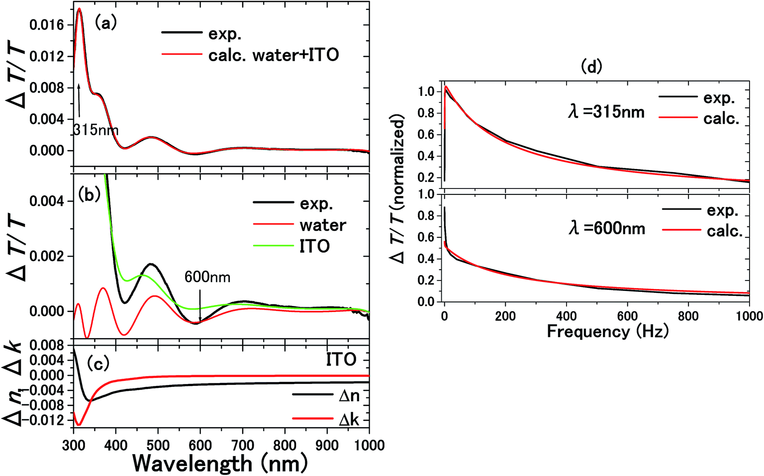 | ||
| Fig. 10 The experimental and calculated results for 0.1 M NaCl aqueous solution with a 300 nm thick ITO electrode are shown in (a).5 From the calculations in (b), it is known that the ΔT/T signals at 315 and 600 nm exclusively originated from the complex refractive index changes Δnc = Δn + iΔk in the SCL and EDL, respectively. Δnc assumed for the SCL in ITO is shown in (c). In order to determine the voltage applied to the EDL and SCL, the impedance of each layer was experimentally determined by the frequency dependence of the signals as shown in (d). The signal intensity decreases with frequency because of the impedances involved in the equivalent circuit. Thus, the impedances of the SCL and EDL were independently determined by different frequency dependence of the signals at 315 and 600 nm to derive the voltage drops of VEDL = 0.85 V and VSCL = 0.15 V. | ||
| Solvent | EDL | SCL | r |
|---|---|---|---|
| H2O | 0.92 | 0.07 | 0.01 |
| MeOH | 0.82 | 0.15 | 0.03 |
| EtOH | 0.93 | 0.01 | 0.06 |
| DMSO | 0.61 | 0.34 | 0.05 |
C. Derivation of Pockels constants
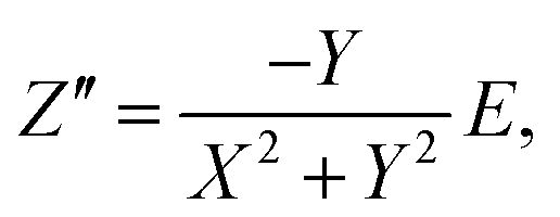
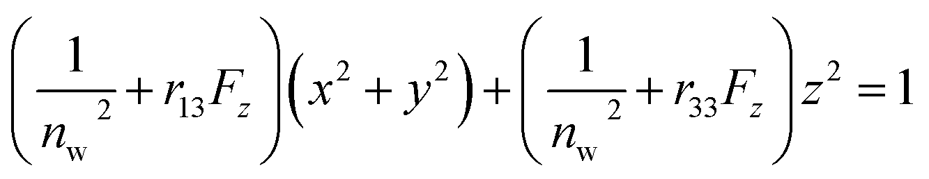
The Pockels constants were determined from the refractive index change and the electric field in the EDL. In fact, the refractive index change is considered to be anisotropic as represented by the refractive index ellipsoid4,5 such that
 | (6) |
 and
and 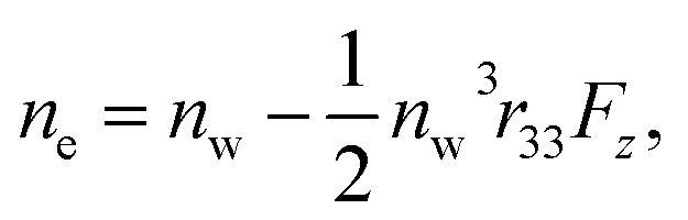 where no is the refractive index of the ordinary ray (the optical electric field E is parallel to the electrode surface while the external electric field F is normal to the surface), ne is the refractive index of the extraordinary ray (both E and F are normal to the surface), nw is the refractive index of the bulk solution, and r13 and r33 are the Pockels constants for the ordinary and extraordinary rays. The refractive index change of solution was assumed to be wavelength independent. In this study, the measurement was performed only at the normal incidence, so that the Pockels constant of solution in the EDL was determined for the ordinary ray, r13, only. The results are listed in Table 2. The value for H2O agrees well with the previous report.5 Note that the values for H2O, MeOH, and EtOH are an order of magnitude larger than those for the typical electro-optic crystal LiNbO3: r33 = 30.8 pm V−1 and r13 = 8.6 pm V−1.1
| Solvent | r13 (pm V−1) |
|---|---|
| H2O | 230 |
| MeOH | 200 |
| EtOH | 84 |
| DMSO | 20 |
V. Discussion
It is remarkable that MeOH and EtOH have as large Pockels constants as H2O. These solvents are distinguished from DMSO in that they are protonic solvents. This fact strongly suggests that the hydrogen bonding is the most important factor in the Pockels effect in the EDL of these liquids. The Pockels constants are arranged as H2O, MeOH, and EtOH in descending order. This agrees with the order of the strength of the hydrogen bond.However, more specifically, the following questions arise immediately in terms of the relative magnitudes of the Pockels constants.
Q1. Why does MeOH have a magnitude very close to that for H2O?
Q2. Why does EtOH have a magnitude less than a half of that for MeOH?
Q3. Why does DMSO have a smaller value by one order of magnitude than H2O?
These facts deserve the highest attention, because they should constitute the key factors to the understanding of the microscopic mechanism of the Pockels effect of water. These questions need to be answered in light of the properties of each solvent. For this purpose, the physical properties of the solvents are tabulated in Table 3.30
| Solvent | Molecular weight | Density (g cm−3) | Dipole moment (D) | Viscosity (mPa s) | Static dielectric constant | Refractive index |
|---|---|---|---|---|---|---|
| H2O | 18.015 | 0.998 | 1.85 | 1.00 | 80.2 | 1.333 |
| MeOH | 32.05 | 0.792 | 1.66 | 0.59 | 33.0 | 1.329 |
| EtOH | 46.07 | 0.789 | 1.44 | 1.2 | 25.3 | 1.361 |
| DMSO | 78.14 | 1.10 | 3.96 | 1.99 | 47.2 | 1.479 |
Regarding the strength of the hydrogen bond, if we adopt the difference (increment) in the boiling point in comparison with non-polar molecules with a similar molecular weight, we obtain Table 4.
| Solvent | Increment in b.p. | Molecular weight | Boiling point | Molecule | Molecular weight | Boiling point |
|---|---|---|---|---|---|---|
| H2O | 261.5 | 18.015 | 100 | Methane | 16.04 | −161.5 |
| MeOH | 153.2 | 32.05 | 64.7 | Ethane | 30.07 | −88.5 |
| EtOH | 120.5 | 46.07 | 78.4 | Propane | 44.1 | −42.1 |
| DMSO | 108.9 | 78.14 | 189 | Benzene | 78.11 | 80.1 |
Notice that DMSO is classified as an aprotonic solvent although it is a protophilic (not protogenic) solvent. Therefore, a large increment in the boiling point is not due to the hydrogen bonding but mainly attributed to its large dipole moment. Therefore, the increment in the b.p. cannot be taken at face value to represent the strength of the hydrogen bond regarding DMSO. Regarding the strength of the hydrogen bond, the hydrogen-bond network, i.e., the average cluster size of molecules due to hydrogen bonding in the pure liquid state, should provide a good measure of the hydrogen-bond strength. The reported cluster size of water ranges from 2 to 280,31 but there is no recent calculation for the mean cluster size in bulk water. More than two decades ago, the mean cluster size at room temperature was reported to be 50,32 8,33 and 5 (ref. 34) by the same authors. Regarding MeOH and EtOH, the average cluster sizes were recently reported independently to be 5.9 for MeOH35 and 4.9 for EtOH.36 DMSO is known to exist mainly as a dimer in the pure liquid state37,38 due to the dipole–dipole Coulomb attraction (not due to hydrogen bonding). Although these average cluster sizes are not experimentally verified values but dependent on the calculation methods to be updated in future, they are one of the good measures for the hydrogen-bond strength.
MeOH and EtOH are similar liquids, thus a difference in the Pockels constant by more than twice is remarkable (Q2). Among the physical properties of them, one cannot find any such physical properties other than viscosity where the magnitude is different by more than twice. Therefore, the viscosity might be one of the important parameters that determines the magnitude of the Pockels effect such that the Pockels constant is negatively correlated with the viscosity value. Note that the voltage division ratio of the DC resistance of the EtOH solution is twice larger than that of the MeOH solution as shown in Table 1. This is consistent with the viscosity values of the solvents, as the ionic mobility is inversely proportional to the viscosity.
A plausible answer to Q1 is also given by considering not only the hydrogen-bond strength but also the solution viscosity. Both the increment in the b.p. and the average cluster size suggest that the hydrogen-bond strength of H2O is about 1.7 times as large as that of MeOH, while the viscosity of H2O is also about 1.7 times as large as that of MeOH. If a positive correlation of the hydrogen-bond strength to the Pockels effect is nearly compensated for by a negative correlation of the viscosity, H2O and MeOH should give almost the same magnitude for the Pockels constant, as was observed.
As a bold hypothesis, if we assume that the magnitude of the Pockels constant is proportional to the value of the hydrogen-bond strength divided by the viscosity, coincidence between this hypothetical value and the relative magnitude of the Pockels constant is excellent as shown in Table 5.
| Solvent | Inc. in b.p. | Cluster size | Hyd. bond strength | Viscosity (mPa s) | H. b. strength/viscosity | Pockels constant |
|---|---|---|---|---|---|---|
| H2O | 261.5 | 1.7 | 1.00 | 1.7 | 1.96 | |
| MeOH | 153.7 | 5.9 | 1.0 | 0.59 | 1.7 | 1.7 |
| EtOH | 120.5 | 4.9 | 0.78 | 1.2 | 0.65 | 0.71 |
| DMSO | 2 | 0.32 | 1.99 | 0.16 | 0.17 |
This is a positive answer to all of the questions: Q1, Q2, and Q3. This coincidence, however, never assures that the physical parameter dependence of the Pockels constant is correctly derived without providing sound physical bases of the microscopic mechanism of the Pockels effect.
It should also be noted that there is an electrode material dependence in the magnitude of the Pockels effect.16 The Pockels constant of water in the EDL on the electrode is larger for ITO electrodes than for GaN electrodes. This should be correlated with the fact that interaction of the water molecules with the solid surface by hydrogen bonding is larger for the oxide surface3,39 than for the nitride surface.
The present results and the electrode material dependence immediately lead to the following scenario. The biased electrode surface strongly interacts with the solvent molecules by hydrogen bonding. The solvent molecules respond as a cluster39 such that cluster volume and shape are strongly affected by the interaction with the electrode surface as well as by a strong electric field in the electric double layer. This responsivity, i.e., the degree of the change in the volume and shape of the cluster, is larger for a smaller viscosity. As a result, for a larger average cluster size (larger hydrogen-bond strength) and for a smaller viscosity, the refractive index change is larger which occurs asymmetrically being correlated with the volume change or deformation of clusters and being specific to the polarity of the electric field in the EDL. This mechanism is plausible because an ab initio calculation result shows that the dynamic polarizability is proportional to the cluster size of water.40
VI. Summary
The Pockels constants, r13, for protonic and aprotonic solvents are evaluated. Protonic solvents, H2O, MeOH, and EtOH, have much larger constants than the aprotonic solvent, dimethyl sulfoxide. Water and MeOH have nearly the same magnitude of Pockels constant, while the Pockels constant of EtOH is less than a half of those of H2O and MeOH. The magnitude of the Pockels constants of these four solvents scales with the hydrogen-bond strength (or average cluster size) divided by the solvent viscosity. This result strongly suggests that the strength of the hydrogen bond is the significant source of the Pockels effect. In other words, the magnitude of the Pockels constant could be used as a physical property which characterizes nonaqueous solvents, especially as a good measure of their hydrogen-bond strength.VII. Appendix
In the measurement of the Pockels constants, the effect of electrolysis of water should be ruled out. In our experiment, electrolysis occurs when the AC voltage >6 V (corresponding to 12 Vp–p) at 20 Hz is applied to the ITO electrodes immersed in 0.1 M NaCl aqueous solution. In this case, irreversible change occurs on the ITO surface such that it turns dark in addition to the generation of bubbles. Therefore we carefully avoided electrolysis by setting the AC voltage at 4 Vp–p, well below the threshold voltage 12 Vp–p.In this paper, NaCl is used as an electrolyte for water though LiCl is used for the other solvents. Fig. 11 shows the ΔT/T signals for NaCl aqueous solution and LiCl aqueous solution. The results agree very well with each other, and are consistent with the previous observation that there was no significant dependence on the kind of electrolyte (between NaCl and NaF4). Even if we take the difference seriously in ΔT/T between these two aqueous solutions, for example the 6% difference at the peak at 791 nm, it could affect only the 3 digit-accuracy of the Pockels coefficient.
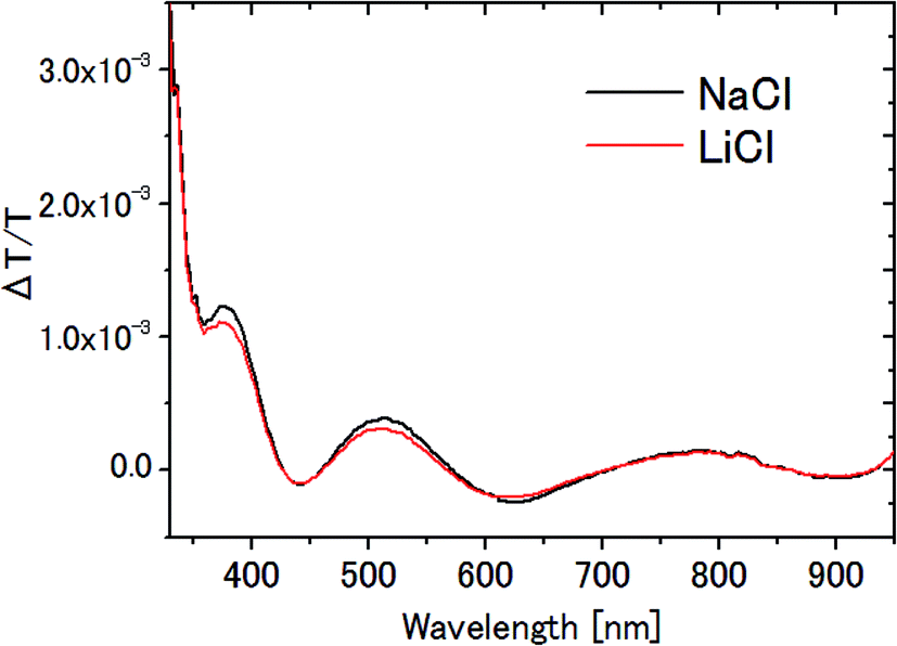 | ||
| Fig. 11 ΔT/T spectra of 0.1 M NaCl and 0.1 M LiCl aqueous solutions. | ||
Since the molar conductivities of aqueous LiCl and NaCl solutions are 115.03 and 126.45 S cm2 mol−1 on the infinite dilution condition,41 the voltage fall in the bulk solution, which is proportional to r in Table 1, is larger in LiCl solution than in NaCl solution. As a result, the voltage applied in the EDL should be larger in NaCl solution than in LiCl solution, yielding a larger signal in NaCl solution than in LiCl solution with the same Pockels constant. The observed small difference is most probably due to this effect.
Conflicts of interest
There are no conflicts of interest to declare.Acknowledgements
This work was supported by a Grant-in-Aid for Scientific Research(C) (Grant Number JP15K05134), and the Japan Society for the Promotion of Science (JSPS).References
- A. Yariv, Quantum Electronics, Wiley, New York, 3rd edn, 1988 Search PubMed.
- D. C. Grahame, Chem. Rev., 1947, 41, 441–501 CrossRef CAS PubMed.
- G. E. Brown Jr, V. E. Henrich, W. H. Casey, D. L. Clark, C. Eggleston, A. Felmy, D. W. Goodman, M. Grätzel, G. Maciel, M. I. McCarthy, K. H. Nealson, D. A. Sverjensky, M. F. Toney and J. M. Zachara, Chem. Rev., 1999, 99, 77–174 CrossRef.
- E. Tokunaga, Y. Nosaka, M. Hirabayashi and T. Kobayashi, Surf. Sci., 2007, 601, 735–741 CrossRef CAS.
- Y. Nosaka, M. Hirabayashi, T. Kobayashi and E. Tokunaga, Phys. Rev. B: Condens. Matter Mater. Phys., 2008, 77, 241401 CrossRef.
- S. Yukita, N. Shiokawa, H. Kanemaru, H. Namiki, T. Kobayashi and E. Tokunaga, Appl. Phys. Lett., 2012, 100, 171108 CrossRef.
- N. Shiokawa, Y. Mizuno and E. Tokunaga, Opt. Lett., 2012, 37, 2655–2657 CrossRef PubMed.
- Y. Suzuki, K. Osawa, S. Yukita, T. Kobayashi and E. Tokunaga, Appl. Phys. Lett., 2016, 108, 191103 CrossRef.
- K. Shiratori and A. Morita, J. Chem. Phys., 2011, 134, 234705 CrossRef PubMed.
- D. Rai, A. D. Kulkarni, S. P. Gejji, L. J. Bartolotti and R. K. Pathak, J. Chem. Phys., 2013, 138, 044304 CrossRef PubMed.
- L. Maschio, M. Rérat, B. Kirtman and R. Dovesi, J. Chem. Phys., 2015, 143, 244102 CrossRef PubMed.
- M. F. Toney, J. N. Howard, J. Richer, G. L. Borges, J. G. Gordon, O. R. Melroy, D. G. Wiesler, D. Yee and L. B. Sorensen, Surf. Sci., 1995, 335, 326–332 CrossRef CAS.
- Y. S. Chu, T. E. Lister, W. G. Cullen, H. You and Z. Nagy, Phys. Rev. Lett., 2001, 86, 3364–3367 CrossRef CAS PubMed.
- W. F. Murphy, J. Chem. Phys., 1977, 67, 5877–5882 CrossRef CAS.
- G. Maroulis, J. Chem. Phys., 1991, 94, 1182–1190 CrossRef CAS.
- H. Kanemaru, Y. Nosaka, A. Hirako, K. Ohkawa, T. Kobayashi and E. Tokunaga, Opt. Rev., 2010, 17, 352–356 CrossRef CAS.
- M. F. Chaplin, Biophys. Chem., 1999, 83, 211–221 CrossRef.
- F. N. Keutsch and R. J. Saykally, Proc. Natl. Acad. Sci. U. S. A., 2001, 98, 10533–10540 CrossRef CAS PubMed.
- P. Wernet, D. Nordlund, U. Bergmann, M. Cavalleri, M. Odelius, H. Ogasawara, L. A. Näslund, T. K. Hirsch, L. Ojamäe, P. Glatzel, L. G. M. Pettersson and A. Nilsson, Science, 2004, 304, 995–999 CrossRef CAS PubMed.
- M. Matsumoto, A. Baba and I. Ohmine, J. Chem. Phys., 2007, 127, 134504 CrossRef CAS PubMed.
- I. Bakó, A. Bencsura, K. Hermannson, S. Bálint, T. Grósz, V. Chihaia and J. Oláh, Phys. Chem. Chem. Phys., 2013, 15, 15163–15171 RSC.
- G. C. Pimentel and A. L. McClellan, The hydrogen bond, Freemann, San Francineo, 1960 Search PubMed.
- Organic Electrochemistry, ed. O. Hammerich and B. Speiser, CRC Press, 5th edn, Revised and Expanded, 2015 Search PubMed.
- K. Izutsu, Electrochemistry in Nonaqueous Solutions, Wiley VCH, 2002 Search PubMed.
- N. Bottka, D. L. Jhonson and R. Glosser, Phys. Rev. B: Solid State, 1977, 15, 2184–2194 CrossRef CAS.
- R. Glosser and B. O. Seraphin, Phys. Rev., 1969, 187, 1021–1024 CrossRef CAS.
- M. Born and E. Wolf, Principles of Optics, Pergamon Press, Oxford, 6th edn, 1980 Search PubMed.
- M. Kobiyama, Theory of Optical Thin Films, Optronics, Tokyo, 2nd edn, 2003, p. 83, in Japanese Search PubMed.
- H. Fricke, Philos. Mag., 1932, 14, 310–318 CrossRef CAS.
- Handbook of Chemistry: Pure Chemistry, Maruzen, 5th edn, 2004 Search PubMed; http://solvdb.ncms.org/; Chronological Scientific Tables, Maruzen, 2016 Search PubMed; CRC Handbook of Chemistry and Physics, ed. W. M. Haynes, CRC Press, 92nd edn, 2011 Search PubMed.
- R. Ludwig, Angew. Chem., Int. Ed., 2001, 40, 1808–1827 CrossRef CAS PubMed.
- G. Nemethy and H. A. Scheraga, J. Chem. Phys., 1962, 36, 3382–3400 CrossRef CAS.
- A. T. Hagler, H. A. Scheraga and G. Nemethy, J. Phys. Chem., 1972, 76, 3229–3243 CrossRef CAS.
- B. R. Lentz, A. T. Hagler and H. A. Scheraga, J. Phys. Chem., 1974, 76, 1531–1550 CrossRef.
- P. Sillren, J. Bielecki, J. Mattsson, L. Borjesson and A. Matic, J. Chem. Phys., 2012, 136, 094514 CrossRef PubMed.
- J. Janecek and P. Paricaud, J. Chem. Phys., 2013, 139, 174502 CrossRef PubMed.
- T. Varnali, Struct. Chem., 1996, 7, 111–118 CrossRef CAS.
- T. Shikata and N. Sugimoto, Phys. Chem. Chem. Phys., 2011, 13, 16542–16547 RSC.
- M. A. Henderson, Surf. Sci. Rep., 2002, 46, 1–308 CrossRef CAS.
- T. K. Ghanty and S. K. Ghosh, J. Chem. Phys., 2003, 118, 8547–8550 CrossRef CAS.
- D. A. MacInnes, The Principles of Electrochemistry, Reinhold, New York, 1961 Search PubMed.
| This journal is © The Royal Society of Chemistry 2017 |