
 Open Access Article
 This Open Access Article is licensed under a
 Creative Commons Attribution 3.0 Unported Licence
The electrochemical behavior of an aluminum alloy anode for rechargeable Al-ion batteries using an AlCl3–urea liquid electrolyte†
Chen Wang,
Junfeng Li,
Handong Jiao,
Jiguo Tu and
Shuqiang Jiao*
and
Shuqiang Jiao*
State Key Laboratory of Advanced Metallurgy, University of Science and Technology Beijing, Beijing, 100083, PR China. E-mail: sjiao@ustb.edu.cn
First published on 23rd June 2017
Abstract
Due to its characteristics of high capacity, low cost, being non-flammable, and involving a three-electron-redox reaction, the aluminum rechargeable battery has received wide attention. Because of these advantages, we focus on a low-cost aluminum alloy anode and detect the discharge/charge reaction mechanism in the aluminum chloride-urea liquid electrolyte at 110–130 °C. The discharge voltage of the battery is about 1.9 V and 1.6 V, and at the current density of 100 mA g−1 the cell can produce a specific capacity of ∼94 mA h g−1. Compared to the pure aluminum anode, the system has a promising future for high efficiency, low-cost energy storage devices.
1. Introduction
Energy is not only a foundation for the national economy and people's livelihood, but also affects the sustainable development of a country and even the whole world. The rechargeable lithium-ion battery has been subject to considerable development for nearly two decades. However, the demand for higher energy/power density and longer service life is increasing. In the large-scale application of rechargeable batteries, the shortcomings of lithium-ion batteries may ultimately reduce their price competitiveness due to lithium storage and unbalanced total lithium ion distribution. This has promoted researches on other systems which are based on sodium (Na), magnesium (Mg), calcium (Ca) and aluminum (Al) carrier ions to utilize the abundance of their electrode raw materials.1–13Taking into account the natural rich reserves and trivalent aluminum, aluminum ion batteries have become potential options for energy storage facilities.14–21 However, due to some problems, aluminum ion batteries are still in basic research state. Such as short cycle life, cathode material excitation, and low and passivated voltage platforms. These problems are mainly due to hardly finding of suitable electrode materials and electrolyte to allow ion transfer in the reversible process. Because anions are expected to have a great effect on performance of rechargeable aluminum batteries,22,23 our group used graphite electrode materials for the new Al-ion battery, allowing the chloroaluminate anions (AlCl4−) to be reversibly intercalated/de-intercalated.21 The battery showed excellent voltage plateau at ca. 1.8 V vs. Al3+/Al, and the capacity can reach ∼70 mA h g−1 over 100 cycles at a current density of 100 mA g−1. At the same time, Dai's group set up a high-performance rechargeable battery.24 More recently, our group has developed a secondary aluminum battery system based on the reversible deposition/stripping of aluminum on the Al anode and the reversibility of the chloroaluminate anions intercalated/de-intercalated at the graphite cathode in the non-combustible (AlCl3–urea) liquid electrolyte.25
However, the high proportion aluminum content of aluminum anode in the AlCl3/urea system is susceptible to be corroded, resulting in capacity decay. At the same time, according to the pure aluminum price and the uncertainty of the cathode reaction process, we select the aluminum alloy foil (thickness 0.6 mm) anode, pyrolyzed graphite cathode and vacuum dried urea/AlCl3 liquid electrolyte to reconstruct Al/graphite in a sealed Teflon electrolytic cell. The batteries are assembled in a Teflon cell operated at 130 °C and 120 °C. We find that the battery with the molar ratio of AlCl3/urea to ∼1.4–1.5 can reach 94–100 mA h g−1 (based on pyrolytic graphite mass) with a coulombic efficiency of 90–102%.
2. Experimental
2.1 Materials
All materials and chemicals are commercially available and used as original. A sealed electrolytic tank was used for the Al-ion battery. A 15 × 15 mm pyrolytic graphite carbon paper (Suzhou Dasen Electronics Material Co., Ltd., mass 10 mg) was fixed by using a molybdenum sheet to form the cathode. The cathode was further wrapped by a piece of glass fiber membrane (GF/A, Whatman) prior to cell assembly. An aluminum alloy foil (General Research Institute for Nonferrous Metals) (25 × 25 mm, 0.6 mm thickness) was used as the anode. Fig. S3† shows the SEM and EDS images of aluminum alloy before testing and after 80 cycles. Before testing, both graphite and aluminum alloy were put into the beaker and washed them with deionized water in the ultrasonic cleaner. Then aluminum alloy was dried in the vacuum oven; meanwhile, pyrolytic graphite was put into the centrifuge, and also dried in the vacuum oven after repeated centrifugal treatment.2.2 Electrochemical measurements
The battery was packaged in a glove box using PG (∼10 mg) cathode and Al alloy foil anode. Urea is firstly added to the beaker and then aluminum chloride is added. After dissolution, the formed solution was transferred into a Teflon electrolytic tank and sealed by PTFE lid electrode.The charge/discharge of the cell was performed using a Neware BTS-53 tester. On the basis of the mass of the pyrolytic graphitic paper, we calculated the specific capacity and current density. Cyclic voltammetry (CV) measurements were performed at a scan rate of 0.5 mV s−1 using a two-electrode configuration with CHI electrochemical analyser (CHI 660E).
2.3 Characterization
Using X-ray diffractometer (XRD, Rigaku, D/max-RB), Raman spectroscopy (Horiba-labram HR evolution) and X-ray photoelectron spectroscopy (XPS, Kratos AXIS Ultra DLD) to detect the crystal structure of the samples. The morphology was characterized by field emission scanning electron microscopy (FESEM, JEOL, JSM-6701F).3. Results and discussion
Fig. 1a and b represent the charge and discharge curves at 110–130 °C. The cut-off voltage is set in the range of 0.4 V to 2.18 V vs. Al3+/Al. The charge and discharge behaviors are obvious, with the average discharge voltage platform of 1.9 V and 1.6 V (vs. Al3+/Al), respectively. We can see from Fig. 1a and b, the specific capacity in the AlCl3/urea (by mole) = 1.5 electrolyte is higher than the AlCl3/urea (by mole) = 1.4 electrolyte when temperature is the same. As the temperature is elevated, the specific capacity is also increased. | ||
| Fig. 1 (a) A current curve of an aluminum alloy/PG battery at 100 mA g−1 with different temperature in AlCl3/urea = 1.5 (by mole) liquid electrolyte, and (b) a current curve in AlCl3/urea = 1.4 liquid electrolyte. Cyclic voltammetry curve of an aluminum alloy/PG at 0.5 mV s−1 (c) in an AlCl3/urea = 1.5 liquid electrolyte and (d) in an AlCl3/urea = 1.4 liquid electrolyte. | ||
Fig. 1c suggests the cyclic voltammetry (CV) of the aluminum alloy anode and the pyrolytic graphite cathode in the AlCl3/urea (by mole) = 1.5 electrolyte, which yields the battery with the highest specific capacity with good electrochemical performance. Two obvious oxidation peaks in the 1.6–1.9 V range, while another well-defined peak appeared at ∼2.05 V (Fig. 1c and d). It can be inferred that the process of this battery is different from the lithium-ion battery, which may occur a number of reactions. Because aluminum ion is a multivalent ion, it can form a variety of ions with the electrolyte, which is necessary to explore the role of the electrolyte in the cell system. These processes, as well as the corresponding reduction events on the negative sweep, were easily correlated with the galvanostatic charge–discharge curve (Fig. 1a and b) for a battery with ∼4.45 mg cm−2 loading of active pyrolytic graphitic material. There are two reasons why the existence of the polarization voltage: (1) Al ions and coordination ions are too large to limit the diffusion of these ions in the electrolyte and the embedding and de-embedding in the pyrolytic graphite layer. (2) Al alloy passivation films can also inhibit the deposition and dissolution of Al. Most importantly, AlCl3/urea = 1.5 at 130 °C is the best condition for generating the battery (Fig. S2†).
In order to keep Coulomb efficiency > 90%, the cut-off voltage of the aluminum alloy/PG battery was set at 2.18 V, and the highest efficiency was observed (Fig. 2a). The low efficiency is probably due to generate side reactions (particularly above 2.18 V) in the electrolyte.
 | ||
| Fig. 2 (a) Galvanostatic curves of aluminum alloy/PG cells with different cut-off charge voltages obtained at 100 mA g−1 in a Teflon electrolytic tank. (b) An aluminum alloy/PG cell charging and discharging at current densities ranging from 100 to 200 mA g−1. SEM images of the original Al alloy (c) and anode obtained from aluminum alloy/PG cells after 80 (d) cycles, respectively, and indicate no dendrite formation over these cycles. | ||
Current density reflects the rate of an electrochemical reaction, when the current is small, the use of active material is more fully; when the current is larger, the electrode polarization is relatively large, hence the use of the active material may not be sufficient. Taking into account the different current density (100, 150, 200 mA g−1), aluminum alloy/PG battery in 30 cycles almost maintain its specific capacity of 90 ± 5% coulombic efficiency (Fig. 2b). The initial coulombic efficiency is more than 100%, mainly because the PG cathode is not fully soaked by electrolyte in the first cycles, causing the battery not fully charged. We can see that the specific capacity can reach 105 mA h g−1 at the beginning with the current density of 100 mA g−1 (Fig. S2†). Subsequently, the specific capacity gradually decreased, and tends to stabilize at ∼94 mA h g−1, showing a large capacity performance. Even at 150 mA g−1 and 200 mA g−1, the discharge capacity is maintained at 92.48 mA h g−1 and 87.72 mA h g−1. The attenuation of the capacitance may be caused by the evaporation of the electrolyte and the instability of the pyrolytic graphite. Moreover, it can be seen that the aluminum alloy before the reaction is very flat, and the aluminum alloy electrode after 80 cycles is partially corrosion. However, the electrode is still smooth, and do not appear dendritic aluminum. According to previous research, the aluminum alloy is cheaper and better corrosion resistance than pure aluminum foil. Further on, SEM and EDS images of the Al alloy before cycling and after 80 cycles indicate the surface of the alloy composition has not changed basically (Fig. S3†). It is well known that the Mg containing compound in alloy has a more negative electrode potential than that of the aluminum matrix, which is firstly dissolved in the electrochemical reaction as anode. Low content of Mg can reduce intergranular corrosion, the hydrogen evolution and corrosion rate, and hence improve the electrochemical performance of aluminum anode. Therefore, it can be speculated that the aluminum alloy can be used directly as the negative electrode in the Al ion battery (Fig. 2c and d).
XRD measurements of pyrolytic graphite paper (Fig. 3a) show that intercalation/de-intercalation of chloroaluminate anions during charge and discharge. The sharp peak of the charged graphite changed from 26.54° to 27.22° and the new peak appeared at 22.82°. The bimodal XRD peak represents a graphene laminate that forms a high strain on the anion intercalation.24 When fully charged, the graphite peak shifts to 27.22° and the wide shoulder may be due to the irreversible change in the accumulation of graphene layers or a small amount of trapping material. The Raman spectra of the original PG and the 80th cycle of charged and discharged pyrolytic graphite (PG) were showed in the Fig. 3. There are two peaks, in which the first one is at 1352 cm−1 (D band), and the second one is at 1580 cm−1 (G band). D-band refers to the presence of structural disorders and defects in the carbon material. It can be found that the D-band was strengthened through the charging process, suggesting that the intercalation of chloroaluminate ions increases the structural defects and disorders on both edges of graphite. The G-band corresponds to the crystallinity of the graphite,26,27 mainly because of the vibrations of sp2 bonded carbon atoms in a two-dimensional hexagonal lattice.27–29 During the process from charging to discharging, the D peak is gradually reduced and the degree of graphitization is increasing. Almost no significant difference shows that PG structure is basically unchanged after the charge and discharge.
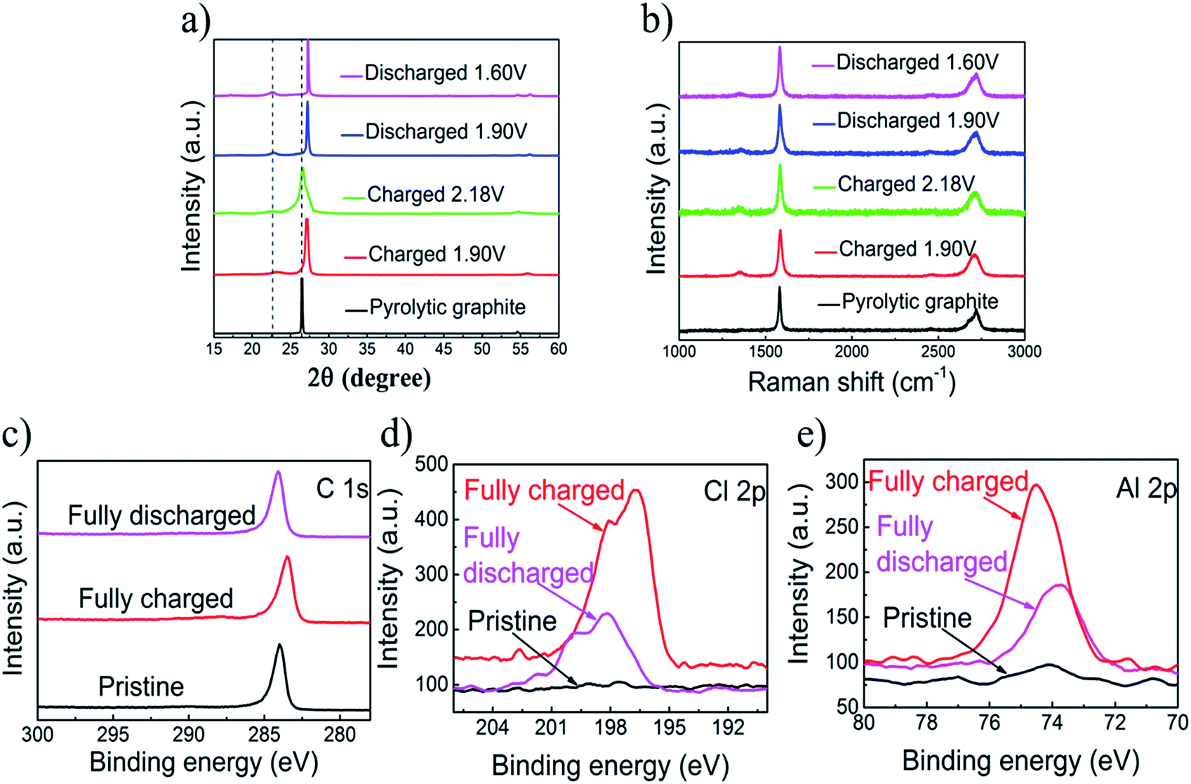 | ||
| Fig. 3 (a) X-ray diffraction patterns of PG in different charging and discharging states. (b) Raman spectra recorded for the PG cathode through a charge–discharge cycle, showing chloroaluminate anion intercalation/de-intercalation into pyrolytic graphite. (c) XPS data of the C 1s peak of a graphitic-foam electrode: pristine, fully charged and fully discharged. XPS data of Al 2p (d) and Cl 2p peaks (e) observed with a PG paper electrode: pristine, fully charged and fully discharged. | ||
The X-ray photoelectron spectrometer (XPS) spectra of the primitive, charged and discharged pyrolytic graphite (PG) paper were showed in Fig. 3c–e. The X-ray photoelectron spectrometer is applied to detect the chemical properties of intercalated substances in PG cathodes. So as to reduce the amount of the captured electrolyte, the cathode was sufficiently washed with deionized water and absolute ethanol. There are no differences between the original and cycled pyrolytic graphite in the C 1s XPS peaks graphic,30 and also no essential information regarding the intercalation/de-intercalation can be observed (Fig. 3c). For the fully charged state, the intercalation of the chloroaluminate ion is demonstrated by the increase in the Al 2p and Cl 2p peaks relative to discharge state (Fig. 3d and e).
When the cut-off voltage of the aluminum alloy/pyrolytic graphite (PG) battery was set to 2.18 V, the aluminum alloy/PG cell shows an apparent discharge voltage platform in the range of 1.9–1.8 V and 1.7–1.5 V (Fig. 4). A fairly high discharge voltage platform is excellent in a number of previous Al-ion storage systems. The charge–discharge cycle shows an excellent electrochemical characteristic of the battery even at 100 mA g−1. The EDS mapping is showed in Fig. 4. For the fully charged state, the intercalation of chloroaluminate ions was evidenced by the increased of Al and Cl elements relative to the discharged state. Furthermore, the mass fraction ratio of Al/Cl approximate 4![[thin space (1/6-em)]](https://www.rsc.org/images/entities/char_2009.gif) :1, which strongly confirmed that chloraluminate ions were inserted/removed into the graphitic carbon.
:1, which strongly confirmed that chloraluminate ions were inserted/removed into the graphitic carbon.
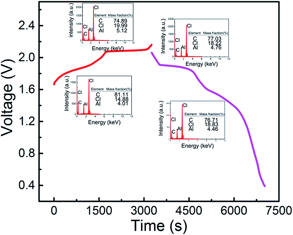 | ||
| Fig. 4 Galvanostatic charge and discharge curves of an aluminum alloy/pyrolytic graphite (PG) cell at a current density of 100 mA g−1. Inset, energy dispersive spectrometer (EDS) at different plateaus. | ||
And then, we investigated the speciation in several AlCl3/urea electrolytes. Raman spectroscopy has previously been used to reveal the existence of chloroaluminate anions in the electrolytes (Fig. 5). We observed the characteristic Raman shifts of AlCl4− (311 cm−1) and Al2Cl7− (349 cm−1) for AlCl3/urea = 1.5. Since Al2Cl7− exists in our AlCl3/urea = 1.5 electrolyte used for the Al battery. The possible reactions (eqn (1)–(3)) in the AlCl3/urea system are proposed as follows:25,31,32
| n(Urea) + AlCl3 → [AlCl2·n(urea)]+ + AlCl4− | (1) |
| AlCl4− + AlCl3 → Al2Cl7− | (2) |
| Al2Cl7− + AlCl3 → Al3Cl10− | (3) |
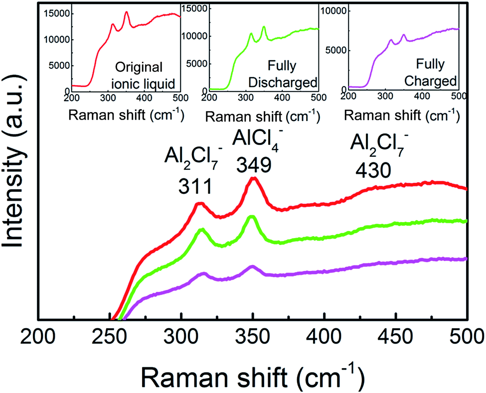 | ||
| Fig. 5 Raman spectra of the ionic liquid electrolyte with a mole ratio of AlCl3/urea = 1.5. Inset, Raman spectra of original, fully charged and fully discharged liquid electrolyte. | ||
Schematic drawing of the cell using an AlCl3/urea liquid electrolyte are suggested and illustrated in Fig. 6. During charging process, [AlCl2·n(urea)]+ cations were transformed into metallic Al and AlCl4− anions at the anode, meanwhile predominantly AlCl4− anions were intercalation between graphite layers at the cathode. And the reverse reaction occurs during discharging process. The reaction of the electrode is suggested as follows:
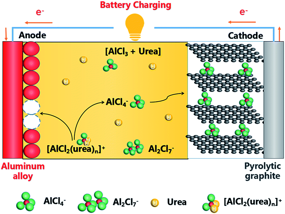 | ||
| Fig. 6 Schematic drawing of the cell during charging using an AlCl3/urea liquid electrolyte. | ||
Anode:
| 2[AlCl2·n(urea)]+ − 3e− ⇌ Al + AlCl4− + 2nurea | (4) |
| 4Al2Cl7− + 3e− ⇌ Al + 7AlCl4− | (5) |
Cathode:
| Cn + AlCl4− ⇌ Cn[AlCl4] + e− | (6) |
| Cn + Al2Cl7− ⇌ Cn[Al2Cl7] + e− | (7) |
4. Conclusion
In this work, with a high and obvious voltage plateau, a novel Al-ion battery based on an Al alloy anode, pyrolytic graphite paper cathode, and low-priced AlCl3–urea liquid analogue electrolyte were successfully established. Intercalation/de-intercalation of chloroaluminate anions during charging/discharging was confirmed by Raman experiments. The present Al alloy/PG battery can afford almost 105 mA h g−1. The battery is cost-competitive in commercial and deserved further investigation. While this work represents an exciting step forward, exploration of numerous combinations of electrolytes and electrode materials remains wide open for further development of Al batteries to achieve ultra-high energy density/cost ratios.Acknowledgements
This work was supported by the Fundamental Research Funds for the Central Universities (FRF-TP-15-002C1).References
- W. Wang, B. Jiang, W. Xiong, H. Sun, Z. Lin, L. W. Hu, J. Tu, J. Hou, H. Zhu and S. Jiao, Sci. Rep., 2013, 3, 3383 CrossRef PubMed.
- A. Ponrouch, C. Frontera, F. Bardé and M. R. Palacín, Nat. Mater., 2016, 15, 169–172 CrossRef CAS PubMed.
- D. Larcher and J. M. Tarascon, Nat. Chem., 2015, 7, 19–29 CrossRef CAS PubMed.
- Z. Yang, J. Zhang, M. C. Kintner-Meyer, X. Lu, D. Choi, J. P. Lemmon and J. Liu, Chem. Rev., 2011, 111, 3577–3613 CrossRef CAS PubMed.
- N. Yabuuchi, K. Kubota, M. Dahbi and S. Komaba, Chem. Rev., 2014, 114, 11636–11682 CrossRef CAS PubMed.
- H. D. Yoo, I. Shterenberg, Y. Gofer, G. Gershinsky, N. Pour and D. Aurbach, Energy Environ. Sci., 2013, 6, 2265–2279 CAS.
- S. Y. Hong, Y. Kim, Y. Park, A. Choi, N. S. Choi and K. T. Lee, Energy Environ. Sci., 2013, 6, 2067–2081 CAS.
- S. Y. Lim, H. Kim, J. Chung, J. H. Lee, B. G. Kim, J. J. Choi, K. Y. Chung, W. Cho, S. J. Kim, W. A. Goddard III, Y. Jung and Y. Jung, Proc. Natl. Acad. Sci. U. S. A., 2014, 111, 599–604 CrossRef CAS PubMed.
- K. W. Nam, S. Kim, E. Yang, Y. Jung, E. Levi, D. Aurbach and J. W. Choi, Chem. Mater., 2015, 27, 3721–3725 CrossRef CAS.
- Z. Chen, Y. Ren, A. N. Jansen, C. K. Lin, W. Weng and K. Amine, Nat. Commun., 2013, 4, 1513 CrossRef PubMed.
- S. Tepavcevic, H. Xiong, V. R. Stamenkovic, X. Zuo, M. Balasubramanian, V. B. Prakapenka, C. S. Johnson and T. Rajh, ACS Nano, 2011, 6, 530–538 CrossRef PubMed.
- Y. Zhu, Y. Wen, X. Fan, T. Gao, F. Han, C. Luo, S. C. Liou and C. Wang, ACS Nano, 2015, 9, 3254–3264 CrossRef CAS PubMed.
- J. Sun, H. W. Lee, M. Pasta, H. Yuan, G. Zheng, Y. Sun, Y. Li and Y. Cui, Nat. Nanotechnol., 2015, 10, 980–985 CrossRef CAS PubMed.
- W. Lv, Z. Li, Y. Deng, Q. Yang and F. Kang, Energy Storage Materials, 2016, 2, 107–138 CrossRef.
- N. Jayaprakash, S. K. Das and L. A. Archer, Chem. Commun., 2011, 47, 12610–12612 RSC.
- S. Liu, J. Hu, N. Yan, G. Pan, G. Li and X. Gao, Energy Environ. Sci., 2012, 5, 9743–9746 CAS.
- J. V. Rani, V. Kanakaiah, T. Dadmal, M. S. Rao and S. Bhavanarushi, J. Electrochem. Soc., 2013, 160, A1781–A1784 CrossRef CAS.
- N. S. Hudak, J. Phys. Chem. C, 2014, 118, 5203–5215 CAS.
- S. Liu, G. Pan, G. Li and X. Gao, J. Mater. Chem. A, 2015, 3, 959–962 CAS.
- Z. Li, K. Xiang, W. T. Xing, W. C. Carter and Y. M. Chiang, Adv. Energy Mater., 2015, 5, 1401410 CrossRef.
- H. Sun, W. Wang, Z. Yu, Y. Yuan, S. Wang and S. Jiao, Chem. Commun., 2015, 51, 11892–11895 RSC.
- H. Wang, S. Gu, Y. Bai, S. Chen, N. Zhu, C. Wu and F. Wu, J. Mater. Chem. A, 2015, 3, 22677–22686 CAS.
- H. Wang, S. Gu, Y. Bai, S. S. Chen, F. Wu and C. Wu, ACS Appl. Mater. Interfaces, 2016, 8, 27444–27448 CAS.
- M. Lin, M. Gong, B. Lu, Y. Wu, D. Wang, M. Guan, M. Angell, C. Chen, J. Yang, J. Y. Hwang and H. Dai, Nature, 2015, 520, 324–328 CrossRef CAS PubMed.
- H. Jiao, C. Wang, J. Tu, D. Tian and S. Jiao, Chem. Commun., 2017, 53, 2331–2334 RSC.
- G. S. Zakharova, C. Jahne, A. Popa, C. Täschner, T. Gemming, A. Leonhardt, B. Büchner and R. Klingeler, J. Phys. Chem. C, 2012, 116, 8714–8720 CAS.
- P. L. S. G. Poizot, S. Laruelle, S. Grugeon, L. Dupont and J. M. Tarascon, Nature, 2000, 407, 496–499 CrossRef CAS PubMed.
- Y. Wang, F. Su, C. D. Wood, J. Y. Lee and X. S. Zhao, Ind. Eng. Chem. Res., 2008, 47, 2294–2300 CrossRef CAS.
- Y. Song, S. Jiao, J. Tu, J. Wang, Y. Liu, H. Jiao, X. Mao, Z. Guo and D. J. Fray, J. Mater. Chem. A, 2017, 5, 1282–1291 CAS.
- P. S. Bagus, E. S. Ilton and C. J. Nelin, Surf. Sci. Rep., 2013, 68, 273–304 CrossRef CAS.
- P. Wasserscheid and W. Keim, Angew. Chem., Int. Ed., 2000, 39, 3772–3789 CrossRef CAS PubMed.
- A. C. Ferrari, Solid State Commun., 2007, 143, 47–57 CrossRef CAS.
Footnote |
| † Electronic supplementary information (ESI) available: Galvanostatic curves of Al alloy/PG cell in an AlCl3/urea = 1.5 (by mole) liquid electrolyte. The SEM and EDS images of the Al alloy, the cycle stability of Al alloy/PG and Al/PG cell. See DOI: 10.1039/c7ra05860h |
| This journal is © The Royal Society of Chemistry 2017 |