 Open Access Article
Creative Commons Attribution 3.0 Unported Licence
Efficient synthesis of nitrogen-doped carbon with flower-like tungsten nitride nanosheets for improving the oxygen reduction reactions
Jie Zhang ,
Jinwei Chen*,
Haowei Yang,
Jinlong Fan,
Feilong Zhou,
Yichun Wang,
Gang Wang and
Ruilin Wang
College of Materials Science and Engineering, Sichuan University, Chengdu, 610065, P. R. China. E-mail: jwchen@scu.edu.cn
First published on 5th July 2017
Abstract
A novel three-dimensional (3D) electrocatalyst composite was successfully prepared through a facile hydrothermal method, consisting of tungsten nitride nanosheets with flower-like morphology (WN FNs) and nitrogen-doped carbon black (N–C). Highly crystalline WN FNs were observed to be uniformly distributed in N–C, and remarkably promoted the catalytic activities toward oxygen reduction reaction (ORR) of the N–C. Moreover, the electrochemical results proved that, WN FNs/N–C composite shows a significantly higher ORR activity with a 4-electron transfer pathway and limiting current density of 5.8 mA cm−2 in alkaline solutions. The stability test of the nanocomposite showed less degradation after 5 h and its methanol tolerance also was enhanced compared with Pt/C. The improved performance of the WN FNs/N–C composite can be attributed to its unique configuration and the increased exposure of active sites, which suggests that it could serve as an ideal candidate for developing high performance ORR catalysts.
1. Introduction
The direct methanol fuel cell (DMFC) has been considered a promising power source for stationary and mobile applications due to its advantages such as high energy density, high conversion efficiency, and low pollution.1–3 The oxygen reduction reaction (ORR) is of great importance at the cathode of a DMFC, meanwhile, Pt-based electrocatalysts have been the most active ORR catalysts yet. However, its high price resulting from Pt loading in electrocatalysts, low catalytic activities towards ORR, and insufficient durability are major obstacles for DMFC commercialization.4,5 In particular, the ORR process has two pathways: an efficient four-electron (4e−) reduction that forms water (H2O) and an inefficient two-electron (2e−) reduction with hydrogen peroxide (H2O2) as an intermediate.6 The sluggish kinetics requires large quantities of Pt-based catalysts, and the methanol crossover effect of the ORR catalyst at the cathode are major concerns in largescale application of DMFC.7,8 Many reported research items have verified that Pt-based electrocatalysts are susceptible to CO and poisoning because of methanol crossover and Pt dissolution/agglomeration.9,10 Numerous studies have been reported about the design of carbon materials employed as supporting materials and methanol tolerant Pt electrocatalysts, such as Pt sandwiched by nitrogen doped carbon nanotubes and a nitrogen doped carbon layer or Pt embedded into the nitrogen doped carbon layer.11–13 But the cost of Pt still is a key factor that prevents the process of commercialization. Therefore, using non-precious metal catalysts for ORR to replace the Pt has been attempted to reduce costs and increase efficiency.To develop non-precious metal catalysts, an important issue is to modify carbon with proper dopants to create the ORR active sites.14,15 An efficient approach to achieve moderate active sites and favorable catalytic activity for ORR is to incorporate N atom into/onto carbon materials. Several carbon materials with dopants including N-doped mesoporous carbon,16 carbon nanodots,17 mesoporous N-doped carbon nanotubes,18 and carbon aerogels19 have been developed as competent catalysts for ORR with good performances. Carbon black (CB) is a common support for catalysts owing to its good electrical conductivity and corrosion resistance.20,21 The nitrogen-doped carbon black (N–C) incorporates nitrogen atoms into adjacent carbon atoms and creates positive charge in favor of electron transfer and oxygen adsorption during ORR.8,22 Although much progresses on ORR activity of N–C have been achieved, there are still some challenges about how to explore hybrid electrocatalysts with the improved ORR performance by introducing other component with homogeneous distribution and upgraded catalytic activity.
Recently, transition metal nitrides (TMNs) have attracted considerable attention due to their unique electronic property that endows Pt-like behavior and insures an advisable adsorption between the surface of the nitrides and the reactants during the reaction.23 Progress has been achieved in the preparation of nanostructured TMNs with enhanced electrochemical performance, such as titanium nitride, tungsten nitride, and vanadium nitride.24–29 However, tungsten nitride (WN) is rarely used than the other nitrides because of the harsh synthesis route, and incorporating nitrogen atoms into the tungsten lattice is thermodynamically adverse at atmospheric pressure.30,31 The synthetic route of WN would undergo high-temperature nitridation, accompanied by the weak anisotropic character of the crystal structure, thereby complicating the control of the shape or preferential facet growth. Thus, we have explored a facile approach to prepare successfully unique WN structures with efficient improvements in performance, in which WN with fine morphology and distribution are closely interrelated with the N–C.
In this work, we report the fabrication of flower-like WN nanosheets (WN FNs) through facile nucleation and growth using a hydrothermal method followed by nitriding. As known to all, N–C could be easily agglomerated due to its particle property, thus leading to inferior ORR activity. A specific morphology of WN can be applied to improve the N–C, while morphology would play a crucial part in optimization of the catalytic performance. WN FNs would be helpful in dispersing the N–C, and also further enhancing the ORR catalytic activity of individual N–C through synergistic effects. Subsequently, a WN FNs/N–C hybrid was developed as an efficient ORR electrocatalyst with excellent catalytic performance in a close to four-electron pathway. Furthermore, the effect of morphologies on catalytic activity was investigated and a possible mechanism was speculated to explain the enhanced catalytic activity. This facile and economic method provides an alternative route to fabrication of non-precious electrocatalysts with improved ORR performance.
2. Experimental
2.1. Materials preparation
All chemicals were of analytical grade and used without further purification. Ammonia gas (NH3) purity is 99.999%. Vulcan XC-72 carbon black (CB) was purchased from Cabot Corporation. The water used throughout all experiments was purified through a Millipore system. The schematic illustration of the synthesis of WN FNs and its composite is depicted in Fig. 1.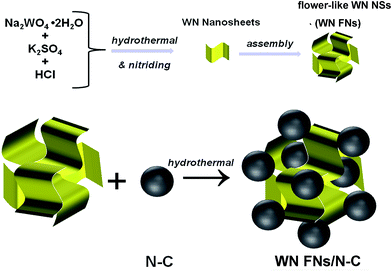 | ||
| Fig. 1 Schematic representation of the synthesis process of 3D flower-like WN nanoarchitectures and its composite. | ||
Nitrogen-doped carbon black (denoted as N–C) was prepared by annealing at 700 °C for 3 h under the NH3/Ar flow of 100 sccm. In a typical synthesis of WN FNs, 7 mmol of Na2WO4·2H2O and 1.75 mmol of K2SO4 were dissolved in 40 mL of deionized water by magnetic stirring to form a transparent solution. Then the pH value was adjusted to 1.0 by the drops of 3 M HCl solution until the appearance of yellow precipitates. Successively, the mixture was transferred to a 100 mL Teflon-lined autoclave and held at 180 °C for 12 h. The yellow precipitates formed in the solution were then collected by filtration, washed with DI water and ethanol several times, and finally dried in a vacuum oven at 80 °C for overnight. The obtained tungsten oxide powder was heated at 450 °C in air for 3 h and then annealed at 700 °C for 3 h under the NH3/Ar flow of 100 sccm to obtain WN FNs.
The WN FNs/N–C nanocomposite was synthesized through one step hydrothermal method. In a typical experiment, 90 mg of N–C were dispersed in 50 mL DI water using ultrasonication for 10 min. To this, 10 mg of as-prepared WN FNs were added and ultrasonicated for 30 min to obtain a homogeneous mixture. After vigorous stirring, the mixture was transferred to 100 mL Teflon-lined autoclave and heated at 180 °C for 6 h. The product was allowed to settle collected by filtration, and purified thoroughly using sufficient DI water. Finally, as-prepared sample was dried overnight. The overall content of WN in nanocomposite was ca. 10 wt%. For comparison, WN nanoparticles (denoted as WN NPs) was prepared through a conventional method as follows: a proper amount of ammonium metatungstate were dispersed in 100 mL deionized water by ultrasonication and heated at 70 °C for 3 h, and then steamed to dry at 100 °C with a continuous stirring. Finally, the power was prepared using the same conditions following the above nitriding procedures. The corresponding WN NPs/N–C composite was prepared in the same hydrothermal condition.
2.2. Physical characterizations
X-ray diffraction (XRD) patterns were obtained using a powder diffractometer (DX-2700, Dandong, China) with a CuKα radiation source. X-ray photoelectron spectroscopy (XPS) measurement were carried out on a Kratos AxisULTRA X-ray Photoelectron Spectrometer incorporating a 165 mm hemispherical electron energy analyzer. Morphologies of electrocatalysts were characterized by scanning electron microscopy (SEM, JSM-5900LV, JEOL Co.) and transmission electron microscopy (TEM, Carl Zeiss SMT, Libra 200FE).2.3. Electrochemical measurement
Cyclic voltammetry (CV) and rotating disk electrode (RDE) measurements were performed using a glassy carbon (GC) electrode with a typical three-electrode system. A graphite plate and Ag/AgCl electrode were used as the counter and reference electrodes, respectively. To prepare the working electrodes, 5 mg of catalyst was ultrasonically suspended in 1 mL ethanol and 50 μL Nafion® solution (5 wt%, Du Pont) for 30 min to form a homogeneous ink. Then 5 and 20 μL of the catalyst inks were dropped onto the GC of 3 and 5 mm in diameter followed by drying for CV and RDE. The electrochemical measurements were carried out on a CHI660D electrochemical workstation (CH Instruments, Inc., Shanghai). Before the CV measurements, the electrolyte was saturated by bubbling Ar or O2 for 30 min. The RDE measurements were performed on a Pine electrochemical system at different rotating rates varying from 400 to 2025 rpm (revolutions per minute) with the scan rate of 10 mV s−1. For a comparison, the commercial Pt/C (20 wt%, Johnson Matthey Co.) was also prepared with the same method with a loading of 160 μgPt cm−2. The electron transfer number (n) can be calculated according to the K–L equation:32| B = 0.2nF(DO2)2/3ν−1/6CO2 |
![[thin space (1/6-em)]](https://www.rsc.org/images/entities/char_2009.gif) 485C mol−1), DO2 is the diffusion coefficient of O2 in 0.1 M KOH (1.9 × 10⁻⁵ cm2 s−1), ν is the kinematic viscosity of 0.1 M KOH (0.01 cm2 s−1), and CO2 is the bulk concentration of O2 dissolved (1.2 × 10⁻⁶ mol cm−3). The electrochemical impedance spectroscopy (EIS) measurements were performed by applying an AC voltage with 10 mV amplitude in a frequency range from 0. 1 Hz to 100 kHz in 5 mM Fe(CN)63−/4− containing 0.5 M KCl.
485C mol−1), DO2 is the diffusion coefficient of O2 in 0.1 M KOH (1.9 × 10⁻⁵ cm2 s−1), ν is the kinematic viscosity of 0.1 M KOH (0.01 cm2 s−1), and CO2 is the bulk concentration of O2 dissolved (1.2 × 10⁻⁶ mol cm−3). The electrochemical impedance spectroscopy (EIS) measurements were performed by applying an AC voltage with 10 mV amplitude in a frequency range from 0. 1 Hz to 100 kHz in 5 mM Fe(CN)63−/4− containing 0.5 M KCl.
3. Results and discussion
3.1. Physical characterization of the catalysts
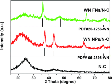
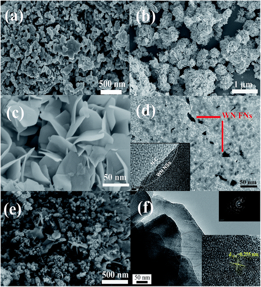
The crystal structure of the N–C, WN NPs/N–C, and WN FNs/N–C were investigated by XRD, as shown in Fig. 2. The pattern of N–C contains two peaks around 23.5° and 43.5°, which originate from the carbon diffractions of (002) and (101), respectively.33 The phase identity of WN NPs/N–C also is confirmed, which is in good accordance with the cubic WN [JCPDS card no. 65-2898]. Noticeably, the pattern of WN FNs/N–C exhibits the characteristic diffraction peaks at 2θ value of 35.8, 48.5, 66.1, and 75.8°, confirming the formation of hexagonal WN [JCPDS card no. 25-1256]. The strong (100) peak at 35.8° suggests the ordered stacking of nanosheets in the flower-like WN nanostructures. We speculate that the distinction was caused by the addition of K2SO4: K+ tends not to be involved in hydrothermal reaction, but along with K+ adsorbed on some planes to inhibit growth of the certain planes and accelerate the growth of the corresponding perpendicular planes hexagonal lattice polycrystal.The morphology and microstructure of the WN nanostructure and their composites are studied using SEM and TEM. Fig. 3a shows WN NPs prepared via the conventional method severely agglomerate to form massive particles. The SEM image of WN FNs (as shown in Fig. 3b and c) reveals the morphology of two-dimensional (2D) WN nanosheets, which usually forms flower-like assembly during nitridation. Fig. 3d shows homogeneous zero-dimensional (0D) N–C and 2D WN sheets in WN FNs/N–C, indicating an interface between N–C and WN (as denoted by the white line, inset) and revealing that carbon layers on N–C side appear to originate from WN surface layers, which is the most significant region for oxygen adsorption or desorption.34 It also could be easily observed that thin nanosheets embedded in carbon to construct a three-dimensional (3D) hybrid (as displayed in Fig. 3e). Furthermore, the individual WN FNs have an average edge length of 100 nm (Fig. 3f). The corresponding selected area electron diffraction (SAED) pattern inset reveals a polycrystal crystalline structure and exhibits well-defined crystalline lattice with lattice spacing of 0.255 nm, corresponding to the (100) plane of WN.
The elemental composition and chemical states in catalysts were characterised by XPS. Fig. 4a shows the survey spectra of N–C, revealing the presence of C 1s and N 1s. Pyridine-like N is the leading species (Fig. 4b) due to its large amount. Specifically, as shown in Fig. 4c, the peak located at 285.5 eV is ascribed to the carbon in C–N bonds.35 Fig. 4d also reveals the peaks of C 1s, N 1s, and W 4f peaks are visible in the survey spectrum. Fig. 4e shows that the W4f BE for WN FNs/N–C hybrid is 35.7 and 37.8 eV with increases relative to that of individual WN reported in literature.36 The shift can be explained by the electron transfer between N–C and WN due to intimate contact and intensive interaction, as confirmed by TEM and XRD. The increase of electrons on the hybrid can facilitate the subsequent ORR.37,38 For the WN FNs/N–C hybrid, the N 1s spectrum (as shown in Fig. 4f) could be deconvoluted into three peaks. Peak I (398.5 eV) was ascribed to N from WN; peaks II (399.5 eV) and III (401.6 eV) were derived from N atoms combined with C atoms. Peak II can be ascribed to the pyrrolic/pyridine N and peak III is indexed to the quaternary N. Except for N type from WN, the predominant N-doped group was pyridinic N and generally it was considered as possible active sites participating in the ORR, which is crucial in ORR performances.39–41 The high resolution spectra in the C 1s region shown in Fig. 4g indicates the high content of sp2 C (BE: 284.6 eV), which would lead to high electrical conductivity and ORR activity.
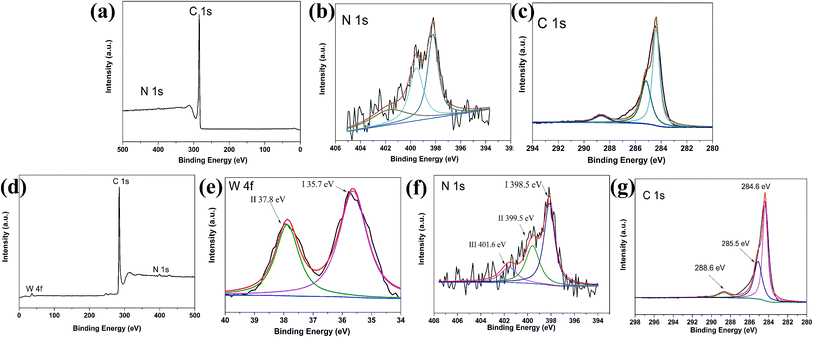 | ||
| Fig. 4 XPS spectra of (a) N–C, (b) N 1s peaks, (c) C 1s peaks, (d) XPS spectra of the WN FNs/N–C, (e) W 4f (f) N 1s, and (g) C 1s peaks. | ||
3.2. Electrochemical characterization of the catalysts
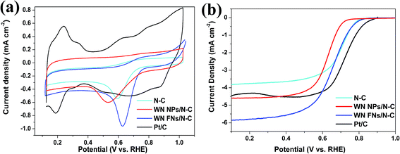
The CV measurement is most popular method for evaluating the ORR activity of synthesized electrocatalyst and CV curves recorded in O2-saturated 0.1 M KOH solutions are shown in Fig. 5a. N–C displayed an obvious cathodic ORR peak current with an onset potential at 0.741 V (vs. RHE) and peak potential at 0.597 V. Significantly, WN FNs/N–C showed superior electrocatalytic property with the onset potential of 0.764 V and peak potential of 0.632 V. It is reported that a more positive onset potential demonstrates the better response of the electrochemical reduction of O2.42 The high positive shift is better than that of N–C and WN NPs/N–C, which suggests better ORR selectivity on the surface of WN FNs/N–C. The result thereby reveals that the WN FNs at the interface of N–C enhance the ORR catalytic performance and facilitate the dispersion of N–C in composite. To explain the relationship between NPs and FNs, we also attempted to explore the interfacial charge transfer using electrochemical impedance spectroscopy as shown in Fig. 6. As shown in Fig. 6a (EIS was recorded in 5 mM Fe(CN)63−/4− containing 0.5 M KCl), the semicircles at high frequency region can be assigned to the charge transfer resistance (Rct).43 Inset is the equivalent circuit, Rs, Rct, and CPE represent the electrolyte resistance, the electron-transfer resistance, and the chemical capacitance, respectively. By fitting the equivalent circuit inset, the Rct values were 64.8 and 29.8 Ω for WN NPs/N–C and WN FNs/N–C, respectively. The low Rct value of WN FNs/N–C generates fast interfacial electron transfer, which is in favor of the high ORR activity. The large Rct induced by the WN NPs may be due to the particle agglomeration during the synthetic process. Fig. 6b illustrates Nyquist plots obtained in O2-saturated 0.1 M KOH with the rotating rates of 1600 rpm, demonstrating that a semicircle corresponds to a charge transfer during reduction reaction.42,44 As compared to the diameter of the semicircle (inset of Fig. 6b), Rct for WN FNs/N–C is smaller than that for WN NPs/N–C, indicating that the enhanced the electron transfer and more efficiently ORR kinetics. Therefore, we can conclude that WN FNs in composite is benefits interfacial charge transfer, greatly decreasing the impedance and avoiding the agglomeration of N–C.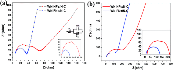 | ||
| Fig. 6 EIS of WN NPs/N–C and WN FNs/N–C conducted in (a) 5 mM Fe(CN)63−/4− containing 0.5 M KCl and (b) in O2-saturated 0.1 M KOH. | ||
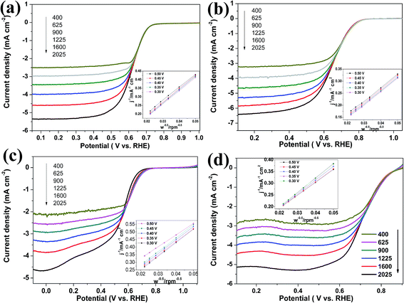
To evaluate the ORR performance, rotating disk electrode (RDE) experiments were performed in O2-saturated 0.1 M KOH with a scan rate of 10 mV s−1 and a rotating speed of 1600 rpm. In Fig. 5b, N–C shows catalytic activity towards ORR, indicating a doping-induced charge redistribution and rapid electron transfer from the N–C to the adsorbed O2. The onset potential for WN FNs/N–C (0.808 V) was higher than those of WN NPs/N–C (0.715 V), thereby indicating that the introduction of WN FNs enhances ORR activity. The limiting current densities for WN NPs/N–C, WN FNs/N–C, and commercial Pt/C were 4.5, 5.8, and 4.4 mA cm−2, respectively. Therefore, WN FNs/N–C exhibits superior ORR activity to those of others because of its faster reaction kinetics and fast reactant diffusion and electron transfer. The other catalyst materials, including WN NPs/N–C, WN FNs/N–C, N–C, and Pt/C, recorded at different rotating rates (400–2025 rpm) with the similar LSV properties (Fig. 7), providing further information on electron-transfer number (n). Calculated from the LSVs, a linear relationship between J−1 and W−0.5 is recorded among the four electrodes (inset of Fig. 7). The n value was calculated to be 3.4 (N–C), 3.5 (WN NPs/N–C), 3.9 (WN FNs/N–C), and 4.0 (Pt/C), respectively. These findings suggest that the Pt-like single step 4e− transfer pathway was induced by WN FNs/N–C hybrid catalyst.
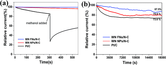
Excellent methanol tolerance and long-term durability are critical in fuel cells.45 The ORR current for the WN FNs/N–C catalyst shows little change with the addition of 3 M methanol due to initiation of methanol oxidation reaction;46 whereas a sharp loss for the Pt/C (Fig. 8a) exists, suggesting that the WN FNs/N–C catalyst has great tolerance for methanol molecules. In Fig. 8b, the ORR current produced on WN FNs/N–C catalyst decreased only by 12.5% during 18![[thin space (1/6-em)]](https://www.rsc.org/images/entities/char_2009.gif) 000 s, whereas the WN NPs/N–C and Pt/C catalyst decreased by 20.2% and 26.4% under the same test conditions. The current decay on Pt/C and WN NPs/N–C might be due to the dissociation and migration of Pt nanoparticles and aggregation of WN NPs during ORR.8 In the composite, an intimate contact can effectively avoid volume changes between N–C and WN nanosheets, thereby preventing the detachment of WN from the conductive carbon matrix during extended operation.
000 s, whereas the WN NPs/N–C and Pt/C catalyst decreased by 20.2% and 26.4% under the same test conditions. The current decay on Pt/C and WN NPs/N–C might be due to the dissociation and migration of Pt nanoparticles and aggregation of WN NPs during ORR.8 In the composite, an intimate contact can effectively avoid volume changes between N–C and WN nanosheets, thereby preventing the detachment of WN from the conductive carbon matrix during extended operation.
Previous literatures also studied the performance of 3D hybrids compared to zero- and one-dimensional catalysts, 3D morphology could provide larger specific surface area, more catalytic sites, and more interconnected electron-transfer access, thus enhancing the electrocatalytic activities.47 For example, the main electrochemical activity of 3D WS2 nanosheets takes place at the edge planes and inherits the abundant active reactive sites of individual 2D nanostructures and the efficient charge transfer of the 3D network assembly.48 A speculated mechanism of the active center for the electrochemical reduction of O2 on WN FNs/N–C is illustrated in Fig. 9. The catalytic activity of the unique hybrid could be explained as follows: (1) WN FNs/N–C prepared by hydrothermal process guarantees close contact, good mechanical adhesion, and an electrical connection between WN nanosheets and N–C, thereby facilitating electron flow from N–C to WN. (2) The 3D configuration enhances oxygen transfer and the increased exposure of active sites. In the present case, WN FNs exhibits a coexisting pathway that involves the 2e− and 4e− routes. The “pseudo four-electron pathway” has been reported to involve a catalytic regenerative process, wherein hydrogen peroxide is chemically converted to hydroxide (OH−) and molecular oxygen (O2) via disproportionation.49 From the above results, we can speculate the mechanism by which the catalytic activity of the WN FNs/N–C hybrid was improved by a mixed two- and four-electron transfer ORR process.
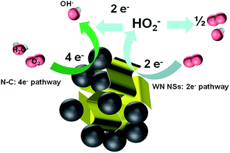 | ||
| Fig. 9 Graphical representation of active centre, electron transfer process, and the ORR mechanism at WN FNs/N–C catalysts. | ||
4. Conclusions
In summary, a unique structure of WN FNs/N–C with an excellent ORR activity and stability has been synthesized. The superior electrocatalytic activity is attributed to the dual active sites composed of N–C and the flower-like WN nanosheets, with a nearly four-electron pathway. As a result, this low-cost catalyst can be a potential alternative for Pt/C, and its stronger methanol tolerance and predominantly long durability would significantly impact DMFC development.Acknowledgements
This work was supported by the Key Research and Development Projects in Sichuan Province (2017GZ0397), the Science and Technology Project of Chengdu (2015-HM01-00531-SF), the National Natural Science Foundation of China (21306119), the Outstanding Young Scientist Foundation of Sichuan University (2013SCU04A23).Notes and references
- J. H. Kim, B. Fang, S. B. Yoon and J.-S. Yu, Appl. Catal., B, 2009, 88, 368–375 CrossRef CAS.
- M.-S. Kim, B. Fang, N. K. Chaudhari, M. Song, T.-S. Bae and J.-S. Yu, Electrochim. Acta, 2010, 55, 4543–4550 CrossRef CAS.
- J. Chang, L. Feng, C. Liu, W. Xing and X. Hu, Energy Environ. Sci., 2014, 7, 1628 CAS.
- K. Jiang, Q. Jia, M. Xu, D. Wu, L. Yang, G. Yang, L. Chen, G. Wang and X. Yang, J. Power Sources, 2012, 219, 249–252 CrossRef CAS.
- E. Proietti, F. Jaouen, M. Lefevre, N. Larouche, J. Tian, J. Herranz and J. P. Dodelet, Nat. Commun., 2011, 2, 416 CrossRef PubMed.
- K. Gong, F. Du, Z. Xia, M. Durstock and L. Dai, Science, 2009, 323, 760–764 CrossRef CAS PubMed.
- T. Sun, Q. Wu, O. Zhuo, Y. Jiang, Y. Bu, L. Yang, X. Wang and Z. Hu, Nanoscale, 2016, 8, 8480–8485 RSC.
- D. Zhou, L. Yang, L. Yu, J. Kong, X. Yao, W. Liu, Z. Xu and X. Lu, Nanoscale, 2015, 7, 1501–1509 RSC.
- U. Kramm, I. Herrmanngeppert, S. Fiechter, G. Zehl, I. Zizak, I. Dorbandt, D. Schmeier and P. Bogdanoff, J. Mater. Chem., 2013, 2, 2663–2670 RSC.
- Y. Yao, H. Xiao, P. Wang, P. Su, Z. Shao and Q. Yang, J. Mater. Chem. A, 2014, 2, 11768–11775 CAS.
- Q. Zhang, X. Yu, Y. Ling, W. Cai and Z. Yang, Int. J. Hydrogen Energy, 2017, 42, 10354–10362 CrossRef CAS.
- Z. Yang, Y. Ling, Y. Zhang and M. Yang, Nanotechnology, 2017, 28, 055404 CrossRef PubMed.
- Z. Yang and N. Nakashima, Sci. Rep., 2015, 5, 12236 CrossRef CAS PubMed.
- M. Vikkisk, I. Kruusenberg, S. Ratso, U. Joost, E. Shulga, I. Kink, P. Rauwel and K. Tammeveski, RSC Adv., 2015, 5, 59495–59505 RSC.
- X. Wang, H. Fu, W. Li, J. Zheng and X. Li, RSC Adv., 2014, 4, 37779 RSC.
- G. A. Ferrero, A. B. Fuertes, M. Sevilla and M. M. Titirici, Carbon, 2016, 106, 179–187 CrossRef CAS.
- R. Liu, H. Zhang, S. Liu, X. Zhang, T. Wu, X. Ge, Y. Zang, H. Zhao and G. Wang, Phys. Chem. Chem. Phys., 2016, 18, 4095–4101 RSC.
- X. Zhu, Y. Zhu, C. Tian, T. Jin, X. Yang, X. Jin, C. Li, H. Wang, H. Liu and S. Dai, J. Mater. Chem. A, 2017, 5, 4507–4512 CAS.
- H. Zhu, Z. Sun, M. Chen, H. Cao, K. Li, Y. Cai and F. Wang, Electrochim. Acta, 2017, 236, 154–160 CrossRef CAS.
- T. Fujigaya, S. Hirata, M. R. Berber and N. Nakashima, ACS Appl. Mater. Interfaces, 2016, 8, 14494–14502 CAS.
- J. Xia, G. He, L. Zhang, X. Sun and X. Wang, Appl. Catal., B, 2016, 180, 408–415 CrossRef CAS.
- J. Xi, Y. Xia, Y. Xu, J. Xiao and S. Wang, Chem. Commun., 2015, 51, 10479–10482 RSC.
- A.-M. Alexander and J. S. Hargreaves, Chem. Soc. Rev., 2010, 39, 4388–4401 RSC.
- P. Yang, D. Chao, C. Zhu, X. Xia, Y. Zhang, X. Wang, P. Sun, B. K. Tay, Z. X. Shen, W. Mai and H. J. Fan, Adv. Sci., 2016, 3, 1500299 CrossRef PubMed.
- B. Avasarala and P. Haldar, Electrochim. Acta, 2010, 55, 9024–9034 CrossRef CAS.
- A. R. Ko, S. B. Han, Y. W. Lee and K. W. Park, Phys. Chem. Chem. Phys., 2011, 13, 12705–12707 RSC.
- H.-C. Park, S.-J. Kim, M.-C. Kim, D.-M. Kim and K.-W. Park, Ceram. Int., 2016, 42, 1933–1942 CrossRef CAS.
- K. Huang, K. Bi, C. Liang, S. Lin, R. Zhang, W. J. Wang, H. L. Tang and M. Lei, Sci. Rep., 2015, 5, 11351 CrossRef CAS PubMed.
- T. Huang, S. Mao, G. Zhou, Z. Wen, X. Huang, S. Ci and J. Chen, Nanoscale, 2014, 6, 9608–9613 RSC.
- J. Xie and Y. Xie, Chem.–Eur. J., 2016, 22, 3588 CrossRef CAS PubMed.
- S. Wang, X. Yu, Z. Lin, R. Zhang, D. He, J. Qin, J. Zhu, J. Han, L. Wang, H.-k. Mao, J. Zhang and Y. Zhao, Chem. Mater., 2012, 24, 3023–3028 CrossRef CAS.
- K. Huang, K. Bi, J. C. Xu, C. Liang, S. Lin, W. J. Wang, T. Z. Yang, Y. X. Du, R. Zhang, H. J. Yang, D. Y. Fan, Y. G. Wang and M. Lei, Electrochim. Acta, 2015, 174, 172–177 CrossRef CAS.
- A. Allahbakhsh and A. R. Bahramian, Nanoscale, 2015, 7, 14139–14158 RSC.
- I. M. Patil, M. Lokanathan, B. Ganesan, A. Swami and B. Kakade, Chem.–Eur. J., 2017, 23, 676–683 CrossRef CAS PubMed.
- A. J. Patil, J. L. Vickery, T. B. Scott and S. Mann, Adv. Mater., 2009, 21, 3159–3164 CrossRef CAS.
- Y. Dong and J. Li, Chem. Commun., 2015, 51, 572–575 RSC.
- H. Yan, C. Tian, L. Sun, B. Wang, L. Wang, J. Yin, A. Wu and H. Fu, Energy Environ. Sci., 2014, 7, 1939 CAS.
- H. Yan, M. Meng, L. Wang, A. Wu, C. Tian, L. Zhao and H. Fu, Nano Res., 2015, 9, 329–343 CrossRef.
- J. Zhang, J. Chen, Y. Jiang, F. Zhou, G. Wang and R. Wang, Appl. Surf. Sci., 2016, 389, 157–164 CrossRef CAS.
- Y.-L. Liu, X.-Y. Xu, P.-C. Sun and T.-H. Chen, Int. J. Hydrogen Energy, 2015, 40, 4531–4539 CrossRef CAS.
- Z. S. Wu, S. Yang, Y. Sun, K. Parvez, X. Feng and K. Mullen, J. Am. Chem. Soc., 2012, 134, 9082–9085 CrossRef CAS PubMed.
- M. Sun, H. Liu, Y. Liu, J. Qu and J. Li, Nanoscale, 2015, 7, 1250–1269 RSC.
- D. Li, H. Chen, G. Liu, M. Wei, L.-x. Ding, S. Wang and H. Wang, Carbon, 2015, 94, 888–894 CrossRef CAS.
- K.-M. Nam, D.-H. Shin, N. Jung, M. G. Joo, S. Jeon, S.-M. Park and B.-Y. Chang, Anal. Chem., 2013, 85, 2246–2252 CrossRef CAS PubMed.
- J. Yin, Y. Qiu, J. Yu, X. Zhou and W. Wu, RSC Adv., 2013, 3, 15655 RSC.
- Q. Wang, Z. Chen, N. Wu, B. Wang, W. He, Y. Lei and Y. Wang, ChemElectroChem, 2017, 4, 514–520 CrossRef CAS.
- M. Liu and J. Li, ACS Appl. Mater. Interfaces, 2016, 8, 2158–2165 CAS.
- J. Tang, Y. Quan, Y. Zhang, M. Jiang, A. M. Al-Enizi, B. Kong, T. An, W. Wang, L. Xia, X. Gong and G. Zheng, Nanoscale, 2016, 8, 5786–5792 RSC.
- C. Y. Su, B. H. Liu, T. J. Lin, Y. M. Chi, C. C. Kei, K. W. Wang and T. P. Perng, J. Mater. Chem. A, 2015, 3, 18983–18990 CAS.
| This journal is © The Royal Society of Chemistry 2017 |


