 Open Access Article
A gold nanodendrite-decorated layered double hydroxide as a bifunctional electrocatalyst for hydrogen and oxygen evolution reactions in alkaline media
M. Taei *,
E. Havakeshian and
F. Hasheminasab
Chemistry Department, Payame Noor University, 19395-4697 Tehran, Islamic Republic of Iran. E-mail: m.taei@ch.iut.ac.ir
First published on 5th October 2017
Abstract
In this work, a gold nanodendrites-CuMgFe layered double hydroxide composite (AuNDs@LDH) was introduced as a bifunctional electrocatalyst for hydrogen and oxygen evolution reactions (HER and OER, respectively) in alkaline media. AuNDs@LDH/GCE was prepared by the coating of the surface of a glassy carbon electrode using the CuMgFe-LDH suspension, and followed by Au electrodeposition. Field emission scanning electron microscopy (FE-SEM) images and energy dispersive X-ray spectroscopy (EDX) analysis showed that nanodendrite-like structures of Au are formed on the LDH film, while Au is electrodeposited as nanoparticles on the GCE (AuNPs/GCE). The performance of the catalysts for HER and OER was investigated using polarization curves, Tafel plots and electrochemical impedance spectroscopy (EIS). AuNDs@LDH/GCE exhibited the lowest onset potential and highest current density in comparison with AuNPs/GCE and LDH@AuNPs/GCE for both the OER and HER. The lower values of Tafel slope and charge transfer resistance indicated that the kinetics of charge transfer for the AuNDs@LDH are faster than those for the other studied electrodes. A durability test was performed using chronopotentiometry method that reveals the highest durability of the AuNDs@LDH for both of the reactions. The synergistic effect of the AuNDs and LDH and the high active surface area of AuNDs could be major parameters for enhanced catalytic performance of the AuNDs@LDH. As a result, this strategy provides a promising approach for the fabrication of highly efficient metal nanostructure-decorated LDHs, which can be used as a catalyst in water electrolyzers.
1. Introduction
The electrochemical splitting of water in alkaline media, which consists of the cathodic hydrogen evolution reaction (HER) and the anodic oxygen evolution reaction (OER), is one of the most promising methods for the large-scale and cost-effective production of hydrogen.1 This process is environmentally friendly, doesn't emit carbon dioxide, and allows the use of inexpensive non-noble metals as catalysts. Nevertheless, one of the main problems in the commercial exploitation of this technique is the potential required to split water, which is substantially greater than the thermodynamic value, due to the high overpotential of the OER and the slow kinetics of the HER with non-noble catalysts.2 Although noble metal based catalysts (e.g., Pt, Pd, Au, Ru, and Ir) provide more catalytic efficiency, they are expensive and their availability is scarce, which has severely restricted the large scale applications of these materials.3 Therefore, the development of inexpensive, more-efficient, durable and earth-abundant electrocatalysts plays a critical role in the commercialization of the water electrolyzers. One of the interesting strategies to create such catalysts is the dispersion of costly catalysts onto a non-noble metal support material. This way can minimize the cost of the production of commodity catalysts owing to the decrease of metal dosage. Moreover, the supports and catalytic active components can interact and function through a synergistic effect, which leads to a remarkable enhancement in the catalytic efficiency.4–6Layered double hydroxides (LDHs) are typical layered materials with the general formula of [M(1−x)2+Mx3+(OH)2]x+(An−)x/n·yH2O, where M2+ and M3+ cations occupy octahedral holes in a brucite-like layer and An− is located in the hydrated interlayer anion.7 LDHs have been proved to be inexpensive, highly active and versatile materials with tunable properties. They have been investigated as catalyst for OER and HER.8–10 Moreover, they have the ability to immobilize the metal nanostructures, which makes them good supports in many catalytic reactions.11–13 To the best of our knowledge, there are few studies about the investigation of catalytic activity of LDHs-supported metal nanostructures in OER and HER, especially; it was found no report for LDH-supported Au nanostructures. Au nanostructures have high active surface area, excellent electrical conductivity and superior catalytic activity.14 Due to these unique characterizations, they (alone or in combination with other materials) have been investigated as good catalysts or electrocatalyst supports for OER15,16 and HER.17,18
In this work, Au is electrodeposited on CuMgFe-LDH coated on the glassy carbon electrode. Electrodeposition is a direct, simple, quick and inexpensive approach for fabrication of nanostructures on a support.19 Then, the surface characterization was performed using field emission scanning electron microscopy (FE-SEM), energy dispersive X-ray spectroscopy (EDX) and cyclic voltammetry (CV). The catalytic activity and durability of the Au nanodendrites-like structures supported on CuMgFe-LDH (AuNDs@CuMgFe-LDH) were studied for both of the OER and HER in alkaline media, and then were compared with those of the electrodeposited Au and CuMgFe-LDH catalysts using electrochemical methods.
2. Experimental
2.1. Chemicals
All chemicals were of analytical grade and were purchased from Merck. All solutions were prepared just before use with doubly distilled water.CuMgFe-LDH was synthesized according to the procedure reported previously.20 Briefly, a solution of 0.4 mol NaOH in 100 mL deionized water was added dropwise into a solution containing Cu(NO3)3·6H2O, Mg(NO3)2·6H2O and Fe(NO3)3·9H2O (the molar ratio of Cu![[thin space (1/6-em)]](https://www.rsc.org/images/entities/char_2009.gif) :
:![[thin space (1/6-em)]](https://www.rsc.org/images/entities/char_2009.gif) Mg
Mg![[thin space (1/6-em)]](https://www.rsc.org/images/entities/char_2009.gif) :
:![[thin space (1/6-em)]](https://www.rsc.org/images/entities/char_2009.gif) Fe is 1
Fe is 1![[thin space (1/6-em)]](https://www.rsc.org/images/entities/char_2009.gif) :
:![[thin space (1/6-em)]](https://www.rsc.org/images/entities/char_2009.gif) 2
2![[thin space (1/6-em)]](https://www.rsc.org/images/entities/char_2009.gif) :
:![[thin space (1/6-em)]](https://www.rsc.org/images/entities/char_2009.gif) 1) in 200 mL of deionized water with vigorous stirring at 65 °C until the final pH = 9 was obtained. Then, the product was transferred into the stainless steel autoclave for 24 h at 120 °C. The product was washed with deionized water several times and dried at 80 °C. Finally, the obtained powder was analyzed using X-ray diffractometer (XRD) and an energy dispersive X-ray spectrometer (EDS). The results21 were in good agreement with those previously reported,20 which showed the successful synthesize of the CuMgFe-LDH. X-ray photoelectron spectroscopy (XPS, Bestec Company, Germany) was used to show the interaction between LDH and Au nanostructures.
1) in 200 mL of deionized water with vigorous stirring at 65 °C until the final pH = 9 was obtained. Then, the product was transferred into the stainless steel autoclave for 24 h at 120 °C. The product was washed with deionized water several times and dried at 80 °C. Finally, the obtained powder was analyzed using X-ray diffractometer (XRD) and an energy dispersive X-ray spectrometer (EDS). The results21 were in good agreement with those previously reported,20 which showed the successful synthesize of the CuMgFe-LDH. X-ray photoelectron spectroscopy (XPS, Bestec Company, Germany) was used to show the interaction between LDH and Au nanostructures.
2.2. Preparation of modified electrodes
To obtain a flat surface and remove surface contaminants, the GCE surface was polished with alumina powder slurry (5 μm) and then, washed ultrasonically in a mixture of ethanol/distilled water (1![[thin space (1/6-em)]](https://www.rsc.org/images/entities/char_2009.gif) :
:![[thin space (1/6-em)]](https://www.rsc.org/images/entities/char_2009.gif) 1 v/v) for 10 minutes and finally, dried in air. In the next step, 0.10 mg of the synthesized LDH was dispersed ultrasonically in 10 mL distilled water to obtain a partial suspension. Then, 5 μL of the LDH suspension was dropped on the GCE surface and allowed to dry in air at room temperature. Then, Au was electrodeposited on the electrode surface by applying 40 continuous cycles cyclic voltammetry in a potential range of −1.5 to 0 V with a scan rate of 50 mV s−1 in a solution containing 0.10 mol L−1 KNO3 and 4.0 × 10⁻³ mol L−1 HAuCl4·3H2O. Finally, to increase the adhesion of the coating to the surface, 10 μL of Nafion solution (2.0% w/v) was dropped onto the electrode. The prepared electrode was named AuNDs@CuMgFe-LDH/GCE.
1 v/v) for 10 minutes and finally, dried in air. In the next step, 0.10 mg of the synthesized LDH was dispersed ultrasonically in 10 mL distilled water to obtain a partial suspension. Then, 5 μL of the LDH suspension was dropped on the GCE surface and allowed to dry in air at room temperature. Then, Au was electrodeposited on the electrode surface by applying 40 continuous cycles cyclic voltammetry in a potential range of −1.5 to 0 V with a scan rate of 50 mV s−1 in a solution containing 0.10 mol L−1 KNO3 and 4.0 × 10⁻³ mol L−1 HAuCl4·3H2O. Finally, to increase the adhesion of the coating to the surface, 10 μL of Nafion solution (2.0% w/v) was dropped onto the electrode. The prepared electrode was named AuNDs@CuMgFe-LDH/GCE.
The same procedure was used to prepare the other catalysts including AuNPs, CuMgFe-LDH and CuMgFe-LDH@AuNPs on the GCE by changing the electrode preparation sequence. It should be noted that the number of cyclic voltammetry in the step of Au electrodeposition was controlled to load the same Au amounts on all of the above-mentioned electrodes.
2.3. Surface characterizations
A field emission scanning electron microscope (FESEM, Hitachi S4160) operated at an accelerating voltage of 25.0 kV equipped with an energy dispersive X-ray spectrometer (EDS) was employed to examine the surface morphology and determine the chemical composition of the prepared electrodes.2.4. Electrochemical measurements
Most electrochemical experiments were performed using a Metrohm instrument, Model 797 VA processor. An Autolab potentiostat-galvanostat, Model PGSTAT302, was used to record chronoamperometric curves and electrochemical impedance spectroscopy (EIS) plots. A conventional three-electrode electrochemical cell consisting of a coated or uncoated GCE with a geometric surface area of 0.0314 cm2 as the working electrode and a platinum wire counter electrode and a reference electrode (Ag/AgCl, KCl 3.0 M) was employed to perform all electrochemical measurements. However, all the reported potentials in this work were referenced to the reversible hydrogen electrode (RHE). The geometric surface area of the as-prepared electrodes was used to normalize the current densities. The electrocatalytic activity of the electrode was evaluated in deaerated 1.0 M KOH solution at room temperature.3. Results and discussions
3.1. Morphological and surface characterizations
To compare the surface morphology of the electrodes, FE-SEM images of their surface were taken. As shown in our previous work,21 Au is electrodeposited on the GCE as Au nanoparticles (AuNPs) with an average diameter of 75 nm. AuNPs cover uniformly whole the GCE surface. The CuMgFe-LDH film on the GCE is composed of agglomerates of fine nanoparticles and macropores between them. Fig. 1A shows that the CuMgFe-LDH film casted on the AuNPs/GCE has a similar morphology to the CuMgFe-LDH casted on the GCE. The FE-SEM images from the CuMgFe-LDH/GCE surface after the Au electrodeposition (Fig. 1B) show that nanodendrites-like structures are formed on the LDH film. Moreover, nanoparticles with the diameter of about 23 nm are seen at some places. The investigation of EDX spectrums shows that the peaks of Au appear after the Au electrodeposition. This indicates the formation of AuNDs on the LDH/GCE. The peaks of Cu, Mg and Fe elements shown in Fig. 1C are also seen before the Au electrodeposition and are attributed to the LDH film. Fig. 1D shows the EDX maps of the SEM image taken from the surface of AuNDs@CuMgFe-LDH/GCE. Dislike Mg and O, Fe and Cu are distributed uniformly on the whole of the surface. The dots related to Au have been gathered where there are nanodendrites, and have been distributed in accordance with them, which demonstrates the dendrites-like nanostructures are of Au. The Au dotes seen in other places, where nanodendrites are not present, can be related to Au nanoparticles. As it is clearly seen, Mg covers mainly parts that are lack of Au nanodendrites. Therefore, it is concluded that AuNDs are formed mainly on LDH sites where a few amount of Mg is present. Although the used electrodeposition procedure and condition are same for AuNDs@CuMgFe-LDH/GCE and AuNPs/GCE, their morphology are very different. This reveals that the use of CuMgFe-LDH as the substrate induces the formation of AuNDs and reduces the size of AuNPs.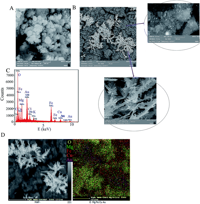 | ||
| Fig. 1 FE-SEM images of LDH@AuNPs/GCE (A), and AuNDs@LDH/GCE (B); the EDX spectrum (C), and EDX map (D) from AuNDs@LDH/GCE surface. | ||
3.2. Electrochemical characterizations
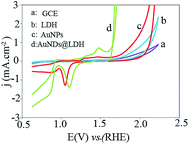
The cyclic voltammogram (CV) of the studied electrodes was recorded at scan rate of 50 mV s−1 in the potential range of 0.63 to 2.23 V (Fig. 2). The CuMgFe-LDH/GCE exhibits a cathodic peak related to the conversion of Fe2+/Fe3+ associated with OH− at about 1.13 V.22 As Au electrodeposited on the CuMgFe-LDH/GCE, strong anodic peaks in the potential ranges of 1.10 to 1.60 V and cathodic peaks in the potential ranges of 0.63 to 1.30 V appear, which are related to the Au oxidation and Au oxides/hydroxides reduction reactions, respectively. All of these peaks are also seen for the AuNPs/GCE. However, their current density for the AuNDs@LDH is higher than that for the AuNPs catalyst. Moreover, the onset potential of the cathodic peak at the range of 1.0 to 1.3 V is significantly decreased when Au is electrodeposited on the CuMgFe-LDH substrate in comparison with AuNPs electrodeposited on the GCE, indicating Fe hydroxides facilitate the reduction of Au oxide species. This may be due to the higher electronegativity of Au with respect to Fe. Therefore, Au oxide species affinity electrons from the CuMgFe-LDH and hence, are reduced at lower potentials.23 As it is evident in the figure, the onset potential (Eonset) of oxygen evolution reaction for the AuNPs/GCE is lower than that for the CuMgFe-LDH/GCE. After the electrodeposition of AuNDs on the CuMgFe-LDH/GCE, OER occurs at much lower Eonset than the AuNPs/GCE and CuMgFe-LDH/GCE.3.3. Oxygen evolution reaction
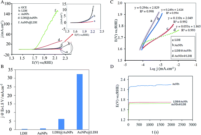
To evaluate the catalytic performance of the electrodes toward OER, the polarization curves of all the prepared electrodes were recorded at a slow scan rate of 5 mV s−1 to minimize the capacitive current, and then corrected for the solution resistance. As shown in Fig. 3A, the AuNDs@LDH/GCE and LDH@AuNPs/GCE exhibit the lower onset potential and the higher current density for OER in comparison with the AuNPs and LDH catalysts. This indicates that there is a synergistic effect between the Au nanodendrites and the CuFeMg-LDH. For a better comparison, the current densities of the electrodes at a fixed potential of 1.80 V vs. RHE were summarized in Fig. 3B. As can be seen, the current density is 32 mA cm−2 for AuNDs@LDH/GCE, which is 82, 48 and 5 times higher than those for the LDH, AuNPs and LDH@AuNPs catalysts, respectively. Moreover, the potential required to reach j = 10 mA cm−2 is 1.76 V for AuNDs@LDH/GCE, while it is 1.89 and 2.22 for the LDH@AuNPs/GCE and AuNPs/GCE, respectively. Therefore, it indicates that AuNDs-decorated the CuFeMg-LDH have a higher catalytic activity toward OER than the LDH@AuNPs/GCE and the AuNPs deposited on the GCE.Tafel plots of the electrodes were obtained to study the OER electrochemical kinetics. As shown in Fig. 3C, the Tafel slopes are reduced when both of the Au nanostructures and LDH are inserted on the electrode surface. The AuNDs@LDH/GCE with the Tafel slope of 53 mV dec−1 exhibits much faster electrochemical kinetics toward the OER in comparison with LDH@AuNPs/GCE, AuNPs/GCE and LDH/GCE with slope of 110, 249 and 294 mV dec−1, respectively.
The durability of the electrodes during OER was evaluated using chronopotentiometry test. A constant current density of 3.2 mA cm−2 was applied to the electrode and the plot of potential versus time was recorded. As shown in Fig. 3D, the AuNDs@LDH/GCE exhibits the lowest operating potential. For the AuNPs/GCE, the operating potential increases by some millivolts after 300 min testing, while it is nearly constant within 2000 s for the AuNDs@LDH and LDH@AuNPs catalysts. It indicates that the synergistic effect of the Au and CuMgFe-LDH results in an increase in the durability of the catalysts.
3.4. Hydrogen evolution reaction
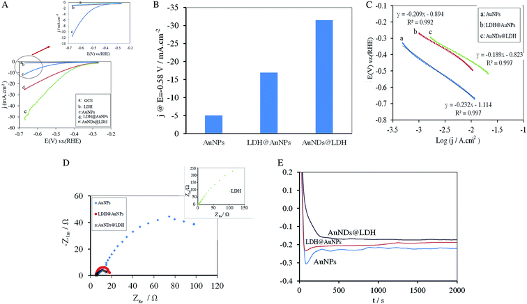
Fig. 4A depicts the HER polarization curves for all the electrodes at a scan rate of 5 mV s−1. HER doesn't occur significantly at the unmodified GCE and the GCE modified with the CuMgFe-LDH in the potential range from −0.67 to −0.27 V. Both of the AuNDs@LDH/GCE and LDH@AuNPs/GCE exhibit much lower HER onset potential values and higher current density than that of the AuNPs-modified GCE. The AuNDs@LDH/GCE shows cathodic current density of 31 mA cm−2 at the potential of −0.58 V, which is about 1.9 and 6.2 times higher than those of LDH@AuNPs/GCE and AuNPs/GCE, respectively (Fig. 4B). The potential at the current density of 10 mA cm−2 for AuNPs/GCE, LDH@AuNPs/GCE and AuNDs@LDH/GCE is −0.66, −0.49 and −0.44 V, respectively, which shows the AuNDs@LDH/GCE exhibits the lowest value. All of the above results indicate that the AuNDs@LDH catalyst has a higher electrocatalytic activity toward HER in comparison with the other studied catalysts.The comparison of Tafel plots in Fig. 4C reveals that Tafel slope reduces significantly when both of the Au nanostructures and CuMgFe-LDH are present in the catalyst. Moreover, it is found that the AuNDs@LDH has lower Tafel slope than LDH@AuNPs, indicating the higher kinetics of HER at the AuNDs@LDH. The Tafel slope for all the catalysts is close to 120 mV dec−1, indicating that the rate determining step for HER is the proton discharge electrosorption (known as Volmer reaction: M + H2O + e ↔ M − Hads + OH−).24
To further investigate the electrode kinetics under HER process, the EIS measurements were carried out from 105 to 10−2 Hz at the AC voltage of −1.60 V with amplitude of 10 mV. As can be seen in Fig. 4D, all of the catalysts exhibit one semicircle, which shows charge transfer process is the rate determining step (RDS). The diameter of semicircles, which is related to charge transfer resistance, reduces in the order AuNDs@LDH < LDH@AuNPs < AuNPs < CuMgFe-LDH. A lower value corresponds to a faster reaction rate. As a result, HER occurs at the AuNDs@LDH with the highest rate.
The durability of the electrodes during HER was studied using chronopotentiometry method. A constant current density of −0.016 mA cm−2 was applied to the electrode for 2000 s. As can be seen in Fig. 4E, in comparison with the other catalysts, AuNDs@LDH exhibits lower potential with negligible oscillation and hence, the higher durability.
3.5. Effective parameters
As found from the obtained results in the previous sections, the LDH@AuNPs and AuNDs@LDH exhibit higher catalytic performance for OER and HER as compared with the AuNPs and CuFeMg-LDH. It is well known that LDHs are potential candidates to catalysis OER and HER.9,25,26 However, they suffer from their inherent low electrical conductivity. Despite LDHs, Au has good electrical conductivity. Moreover, it is accounted as an appropriate catalyst that has strong affinity to oxygen and/or oxygen-containing groups (e.g. OHad−).27,28 Therefore, the Au nanostructures at the LDH@AuNPs and AuNDs@LDH, in addition to the increase of electrical conductivity, can catalysis OER and HER. Moreover, since Au is the most electronegative metal, it affinities strongly the electrons of CuMgFe-LDH and thus facilitates the oxidation of the metal oxides. This leads to a promotion in the formation of transition-metal ions at higher oxidation states, which are accounted as active sites for OER and HER.16,23The electronic interactions within the CuFeMg-LDH and Au nanostructures can be observed experimentally using cyclic voltammetry method. Some electrodes with different amounts of LDH and constant amount of Au were fabricated. Cyclic voltammogram of each electrode was obtained (Fig. 5A). It is observed that the cathodic peaks related to the Au oxides/hydroxides reduction reactions in the range of 0.20 to 1.0 V are shifted to more positive potentials as LDH loading is increasing. Moreover, the overpotential of OER decreases by increase in LDH amount. All of these results suggest an electronic interaction between the LDH and Au nanostructures.15,29 Moreover, X-ray photoelectron spectroscopy (XPS) was employed to determine the valence state and interaction of metals/metal ions. Fig. 5B shows the XPS spectrums of Au 4f before and after the Au electrodeposition on the LDH/GCE. After electrodeposition, two main peaks are observed at 83.3 and 87.0 eV, corresponding to the binding energies of Au 4f7/2 and Au 4f5/2, respectively. The XPS characteristic peaks for metallic Au0 appear at 84.0 and 87.7 eV.30 Therefore, this suggests that the Au nanostructures are electrodeposited as Au0 on the LDH/GCE. The negative shift (0.7 eV) indicates that the electron transfer is done from the LDH to the AuNSs. XPS spectrums of Cu 2p and Fe 2p before and after the Au electrodeposition are also compared in Fig. 5C and D, respectively. Binding energies at 930.7 (Cu 2p3/2) and 951.6 eV (Cu 2p1/2) are related to Cu(OH)2 species. Two main peaks at 711.7 (Fe 2p3/2) and 724.1 eV (Fe 2p1/2), indicating the presence of the Fe3+ cation.31 After Au electrodeposition, these peaks shift to the higher energies, demonstrating the electron transfer from the LDH to AuNSs. All of these results confirm the presence of an electronic interaction between the LDH and AuNSs, which induces the synergistic effects of the Au nanostructures and CuFeMg-LDH in OER and HER. Therefore, it results in a decrease in Eonset and an increase in the current density and hence, an enhancement in catalytic activity and durability of the catalysts.
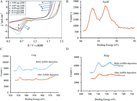 | ||
| Fig. 5 Cyclic voltammograms of the AuNDs@LDH/GCE with different amounts of LDH in 1.0 M KOH at scan rate of 50 mV s−1 (A); and XPS spectrums for Au (B), Cu (C), and Fe (D). | ||
To find why the catalyst performance of AuNDs@LDH is better than LDH@AuNPs, the electrochemically active surface area provided using AuNDs and AuNPs (Sa) for each electrode was calculated using Sa (cm2) = Q/390, where the value of 390μC cm2 refer to the charge required to reduce AuO monolayer on the unit surface area of the electrode and Q is the total charge corresponding to the reduction of AuO monolayer formed on the electrode surface.32 The value of Q was obtained by recording cyclic voltammetry of each electrode in 0.10 M H2SO4 and then, the estimation of the area of the peak related to the reduction of Au oxide species. The value of Sa is obtained to be 0.029, 0.025 and 0.052 cm2 for the AuNPs, LDH@AuNPs and AuNDs@LDH, respectively. Due to the coating of the AuNPs active sites via the LDH, Sa for the LDH@AuNPs is lower than that of the AuNPs. Sa for AuNDs@LDH is much higher than that of AuNPs, due to the nanodendrite-like structure of Au electrodeposited on the LDH. Indeed, the nanodendrites provide higher accessible active sites for the reactions, which results in higher current density for the AuNDs@LDH catalyst with respect to the LDH@AuNPs.
4. Conclusion
Gold nanodendrites were fabricated simply on CuMgFe-LDH film-coated GCE (AuNDs@LDH/GCE) through electrodeposition method and then, its catalytic activity for OER and HER was investigated in 1.0 M KOH. The results showed that the LDH substrate plays a critical role to electrodeposit Au as nanodendrites. The AuNDs@LDH catalyst has higher catalytic performance and durability when compared with AuNPs/GCE and LDH@AuNPs/GCE. This enhancement in catalytic activity could be related to synergistic effects between the LDH and AuNDs and high active surface area provided by AuNDs. Accordingly, the AuNDs@LDH can be used as a bifunctional electrocatalyst for the overall water-splitting. This strategy could be extended for the preparation of other metal-coupled LDH materials for a broad range of technological applications.Conflicts of interest
There are no conflicts to declare.References
- S. H. Hong, S. H. Ahn, I. Choi, S. G. Pyo, H. J. Kim, J. H. Jang and S. K. Kim, Appl. Surf. Sci., 2014, 307, 146–152 CrossRef CAS.
- B. S. Yeo and A. T. Bel, J. Phys. Chem. C, 2012, 116, 8394–8400 CAS.
- Y. Fang, X. Li, Y. Hu, F. Li, X. Lin, M. Tian, X. An, Y. Fu, J. Jin and J. Ma, J. Power Sources, 2015, 300, 285–293 CrossRef CAS.
- C. H. Zhou, Appl. Clay Sci., 2011, 53, 87–96 CrossRef CAS.
- B. Zhang, J. Fang, J. Li, J. J. Lau, D. Mattia, Z. Zhong, J. Xie and N. Yan, Chem.–Asian J., 2016, 11, 532–539 CrossRef CAS PubMed.
- J. Fang, J. Li, B. Zhang, X. Yuan, H. Asakura, T. Tanaka, K. Teramura, J. Xie and N. Yan, Nanoscale, 2015, 7, 6325–6333 RSC.
- Y. Kuang, L. Zhao, S. Zhang, F. Zhang, M. Dong and S. Xu, Materials, 2010, 3, 5220–5235 CrossRef CAS PubMed.
- Z. Liu, C. Yu, X. Han, J. Yang, C. Zhao, H. Huang and J. Qiu, ChemElectroChem, 2016, 3, 906–912 CrossRef CAS.
- W. Ma, R. Ma, C. Wang, J. Liang, X. Liu, K. Zhou and T. Sasaki, ACS Nano, 2015, 9, 1977–1984 CrossRef CAS PubMed.
- L. Qian, Z. Lu, T. Xu, X. Wu, Y. Tian, Y. Li, Z. Huo, X. Sun and X. Duan, Adv. Energy Mater., 2015, 5, 1500245 CrossRef.
- J. Zhao, M. Shao, D. Yan, S. Zhang, Z. Lu, Z. Li, X. Cao, B. Wang, M. Wei, D. G. Evans and X. Duan, J. Mater. Chem. A, 2013, 1, 5840–5846 CAS.
- L. Sobhana, M. Sarakha, V. Prevot and P. Fardim, Appl. Clay Sci., 2016, 134, 120–127 CrossRef CAS.
- A. Mignani, B. Ballarin, M. Giorgetti, E. Scavetta, D. Tonelli, E. Boanini, V. Prevot, C. Mousty and A. Iadecola, J. Phys. Chem. C, 2013, 117, 16221–16230 CAS.
- J. Fang, B. Zhang, Q. Yao, Y. Yang, J. Xie and N. Yan, Coord. Chem. Rev., 2016, 322, 1–29 CrossRef CAS.
- J. W. D. Ng, M. García-Melchor, M. Bajdich, P. Chakthranont, C. Kirk, A. Vojvodic and T. F. Jaramillo, Nat. Energy, 2016, 1, 16053–16061 CrossRef CAS.
- Y. Zhou and H. C. Zeng, J. Phys. Chem. C, 2016, 120, 29348–29357 CAS.
- J. Lu, W. Zhou, L. Wang, J. Jia, Y. Ke, L. Yang, K. Zhou, X. Liu, Z. Tang, L. Li and S. Chen, ACS Catal., 2016, 6, 1045–1053 CrossRef CAS.
- T. Brülle, W. Ju, P. Niedermayr, A. Denisenko, O. Paschos, O. Schneider and U. Stimming, Molecules, 2011, 16, 10059–10077 CrossRef PubMed.
- Nanostructured materials in electrochemistry, ed. A. Eftekhari, John Wiley & Sons, 2008 Search PubMed.
- S. Xia, L. Zhang, X. Zhou, G. Pan and Z. Ni, Appl. Clay Sci., 2015, 114, 577–585 CrossRef CAS.
- M. Taei, E. Havakeshian, F. Abedi and M. Movahedi, Int. J. Hydrogen Energy, 2016, 41, 13575–13582 CrossRef CAS.
- M. Shao, F. Ning, J. Zhao, M. Wei, D. G. Evans and X. Duan, Adv. Funct. Mater., 2013, 23, 3513–3518 CrossRef CAS.
- Z. Zhuang, W. Sheng and Y. Yan, Adv. Mater., 2014, 26, 3950–3955 CrossRef CAS PubMed.
- G. Kreysa and B. Hakansson, J. Electroanal. Chem., 1986, 201, 61–83 CrossRef CAS.
- M. Gong, Y. Li, H. Wang, Y. Liang, J. Z. Wu, J. Zhou, J. Wang, T. Regier, F. Wei and H. Dai, J. Am. Chem. Soc., 2013, 135, 8452–8455 CrossRef CAS PubMed.
- X. Long, J. Li, S. Xiao, K. Yan, Z. Wang, H. Chen and S. A. Yang, Angew. Chem., 2014, 126, 7714–7718 CrossRef.
- F.-Q. Shao, X.-X. Lin, J.-J. Feng, J. Yuan, J.-R. Chen and A.-J. Wang, Electrochim. Acta, 2016, 219, 321–329 CrossRef CAS.
- A. Morozan, V. Goellner, A. Zitolo, E. Fonda, B. Donnadieu, D. Jones and F. Jaouen, Phys. Chem. Chem. Phys., 2015, 17, 4047–4053 RSC.
- M. W. Louie and A. T. Bell, J. Am. Chem. Soc., 2013, 135, 12329–12337 CrossRef CAS PubMed.
- S. K. Movahed, M. Fakharian, M. Dabiri and A. Bazgir, RSC Adv., 2014, 4, 5243–5247 RSC.
- W. Gao, Y. Zhao, J. Liu, Q. Huang, S. He, C. Li, J. Zhao and M. Wei, Catal. Sci. Technol., 2013, 3, 1324–1332 CAS.
- S. Trasatti and O. A. Petrii, J. Electroanal. Chem., 1992, 327, 353–376 CrossRef CAS.
| This journal is © The Royal Society of Chemistry 2017 |

