 Open Access Article
Creative Commons Attribution 3.0 Unported Licence
Hierarchically organized Li–Al-LDH nano-flakes: a low-temperature approach to seal porous anodic oxide on aluminum alloys†
D. Mata *a,
M. Serdechnovab,
M. Mohedanobc,
C. L. Mendisbd,
S. V. Lamakab,
J. Tedime,
T. Hackf,
S. Nixonf and
M. L. Zheludkevichbg
aSmallmatek – Small Materials and Technologies, Rua dos Canhas, 3810-075 Aveiro, Portugal. E-mail: diogo.mata@smallmatek.pt
bInstitute of Materials Research, Helmholtz-Zentrum Geesthacht, Max-Planck-Straβe 1, 21502 Geesthacht, Germany
cDepartamento de Ciência de Materiales, Facultad de Ciências Químicas, Universidad Complutense, 28040 Madrid, Spain
dBrunel – Centre for Advanced Solidification Technology, Brunel University London, Uxbridge UB8 3PH, UK
eCICECO, Dep. Materials and Ceramic Engineering, University of Aveiro, 3810-193, Aveiro, Portugal
fAirbus Group Innovations, 81663 Munich, Germany
gFaculty of Engineering, Christian-Albrechts-University of Kiel, Kaiserstr. 2, D-24143 Kiel, Germany
First published on 13th July 2017
Abstract
This work suggests a low-temperature sealing approach for tartaric–sulfuric acid (TSA) anodized AA2024 based on hierarchically organized Li–Al-layered double hydroxide (LDH) structures. The new proposed sealing is expected to be directly competitive to the standard hot water sealing (HWS) approaches because of its reduced treatment temperature and high protection efficiency. A hierarchical organization of in situ formed LDH nano-flakes across the depth length of the TSA pores, from the macrodown to the nano-size range, was observed with transmission electron microscopy (TEM). Electrochemical impedance spectroscopy (EIS) studies showed that the densely packed LDH arrangement at the porous oxide layer is directly related to the drastically improved barrier properties of TSA. Moreover, LDH flake-like structures worked as “smart” reservoirs for corrosion inhibiting vanadium species (VOx) that are released on demand upon the onset of corrosion. This was confirmed using a scanning vibrating electrode technique (SVET), giving relevant insights into the time-resolved release activity of VOx and the formation of the passivation layer on cathodic intermetallics, corroborated with EDX and analytical Raman spectroscopy. Passive and active corrosion protection was imparted to the anodic layer via new Li–Al-LDH structures with long-term protection exceeding that of standard HWS procedures.
1. Introduction
The escalating fabrication demands for “green” aircrafts following the latest European guidelines have set new challenges in the selection of materials and processes in the aeronautic industry. The eco-design of pioneering surface treatments against corrosion failure with performance and costs matching those of the chromate-based ones is a challenge up to date.1Relevant breakthroughs in new protective systems free of toxic chromates have been done in recent years, particularly for 2xxx series aluminum alloys such as AA2024, which has been widely explored in the aeronautic industry. An important step-forward in this crossroad was accomplished through successful replacement of chromic acid anodizing (CAA) by chromium-free tartaric–sulfuric acid anodizing (TSA).1–3 The anodization with tartaric acid has been proven to enhance corrosion resistance,2 and increases paint adhesion without a negative effect on the fatigue resistance compared to other acidic mixtures.4 The key technical requirements for the anodizing process of aluminum are fulfilled with TSA by which homogeneous porous oxide layers with morphologies close to those produced in CAA treatments are obtained.5 Nevertheless, pre-anodized parts without good sealing or painting are not effectively protected against corrosion. The layer of aluminum oxide formed during anodizing is highly porous and is not an efficient barrier.3 Therefore, as a standard procedure to reduce porosity, anodized parts are post-treated with sealing3 or painting.6 While the TSA anodizing process was found successful in forming consistent oxide layers, the subsequent step of sealing of pores still needs technical improvements.
Up to now, hot water sealing (HWS) is the most commonly used method to improve corrosion resistance of anodized aluminum.3,7 It promotes the hydration of the porous and barrier layers of the anodic oxide followed by a volume increase, and which seals the pore channels. However, the sealing along the pore is not uniform, when the top of the pore is sealed water can no longer pass through the pore, thus the innermost sections are only partially sealed.8 Besides this drawback, the HWS provides only barrier protective properties. To add active corrosion-inhibiting properties to the sealing layer, mainly Cr(VI)-containing solutions, such as Henkel Alodine® 1200,3 have been employed at industrial level. Therefore, there is an urgent demand to replace the toxic Cr(VI) with less harmful alternatives that meet the standard corrosion resistance requirements and the extreme conditions experienced during the on-duty life of aircrafts. Many alternative candidates are found in literature including Cr(III) among others,9 but their performance still do not match that of Cr(VI).
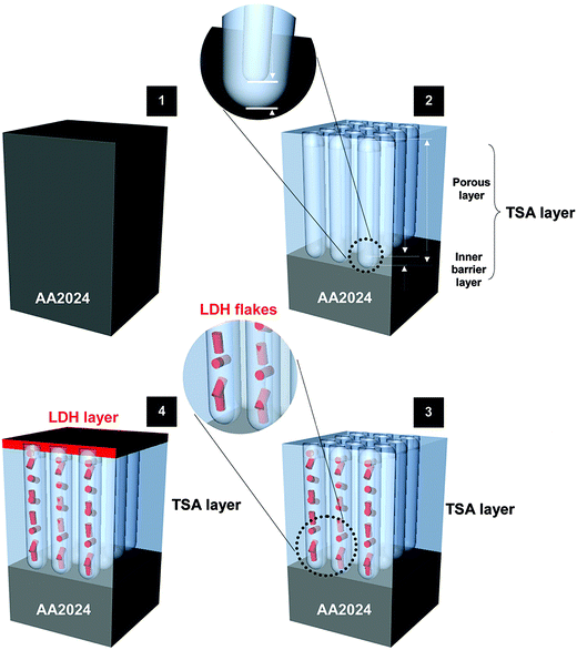
Li–Al-LDH structures intercalated with a corrosion inhibitor are proposed as a new integrated approach for sealing TSA treated AA2024 (Fig. 1) and a promising candidate to replace harmful Cr(VI)-based sealing. This work follows previous encouraging results reported with Zn–Al-LDH on bare,10–12 TSA treated AA2024-T3 (ref. 13) and PEO coated substrates.14 In these works a multi-level protection was explored with LDH working as (1) physical barriers to seal the pores (passive protection) and also “smart” ion-exchanger providing synergistic active corrosion protection. The latter is achieved via (2) on demand controlled release of corrosion inhibitors, together with (3) absorption/entrapping of corrosive ions (e.g. Cl−, SO42−, OH−). However, Zn–Al LDH is growing on Al substrates only at relatively high temperature, close to water boiling point. This fact implies important technological limitations and reduces economic feasibility of the process for many applications.
The protection properties of Li–Al-LDH clay-type conversion coatings have been proposed in the 1990s by Buchheit et al.15 not only on AA2024, but also on other aluminum alloys such as AA1100, AA6061 and AA7075. Additionally, more recently Visser et al. have studied paint systems loaded with Li-based pigments which are able to release Li-cations to facilitate in situ formation of a LDH layer in the coating defect on AA2024 unclad TSA treated plates.16,17 The remarkable results of standard salt spray test shed light on the high potential of Li–Al-LDH as protective conversion coatings. The formation of Li–Al LDH in the defects during the corrosion tests was suggested to be the main active corrosion protection mechanism of the coatings with Li salts as anti-corrosion pigments. Moreover, the demonstrated results suggest that Li–Al LDH can be formed at relatively low temperature in a short time when Li cations are present in the solution. This fact has triggered the idea that Li-based LDH can be a better alternative for sealing porous anodic layers in comparison to Zn–Al counterpart.
Li–Al-LDH system has unique intercalation properties, distinct from those of M2+–M3+ LDH, mainly caused by the high flexibility of its hydroxide layers resembling those found in graphite materials.18 Those intercalation properties are referred to (1) a wider variety of intercalation of inorganic and organic guests such as corrosion inhibitors18–20 and (2) staging behavior in the anion-exchange intercalation reactions, which is a rare example of this phenomenon in hydrotalcite-type minerals.18 The staging means that it is possible to have two different anion guests in the same host lattice. Additionally, the amount of the first and second guests in the host can be set using stoichiometric amounts of each guest during the first- and second-stage intercalation reaction.18
This work focuses on the optimization of the synthesis and intercalation routes of Li–Al-LDH sealing of TSA treated AA2024. Process parameters such as pH and temperature of the bath were thoroughly evaluated to understand their influence on morphology and corrosion performance of the sealed TSA coatings. Electrochemical impedance spectroscopy was used to evaluate the barrier and active properties of the LDH sealing loaded with corrosion inhibiting VOx species. The localized scanning vibrating electrode technique gave information about the kinetics of corrosion processes in confined artificial defects. Formation of the passivation layer on defects mediated by the releasing of the vanadate inhibitor is discussed based on local EDX and Raman measurements. Overall, data sheds light on the corrosion protection of TSA treated AA2024 achieved through a cost-effective new environmentally friendly sealing process that can be run at room temperature and it is highly competitive with other current reference solutions, such as hot water sealing, here also studied for comparative purposes.
2. Experimental section
2.1. Materials
Panels of 2024-T3 aluminum alloy with the following composition were used as substrates: Cu 3.8–4.9 wt%, Mg 1.2–1.8 wt%, Mn 0.3–0.9 wt%, Fe 0.5 wt%, Si 0.5 wt%, Zn 0.25 wt%, Ti 0.15 wt%, Cr 0.1 wt%, other 0.15 wt%, balance Al.All chemicals used in the current work are of analytical grade: lithium nitrate (LiNO3, ≥99.5%, Carl Roth), sodium nitrate (NaNO3, ≥99%, Merck), sodium hydroxide (NaOH, ≥99% Merck), sodium vanadium oxide (NaVO3, 96%, Lancaster Synthesis), sodium chloride (NaCl, ≥99.8%, Sigma-Aldrich), DL-tartaric acid (≥99%, Sigma-Aldrich), sulfuric acid (H2SO4, 95–98%, Alfa Aesar).
2.2. Tartaric–sulfuric acid anodizing of AA2024-T3
Prior to anodizing, AA2024-T3 panels (8 × 2 cm2) were treated with standard commercial procedures, including degreasing, cleaning and chemical etching steps, as described in detail previously.13 The pre-treatment of the surface was followed by an anodizing process (blank panels) in a tartaric (0.53 M C4H6O6)–sulfuric acid (0.46 M H2SO4) bath (TSA) at 37 °C, with a voltage of 14 V for 25 min to obtain an anodic coating thickness of 3 μm. Following the treatment, panels were rinsed in deionized water and dried in ambient conditions.2.3. Sealing of TSA treated AA2024-T3
The standard sealing of the anodized panels was accomplished by hot-water sealing (HWS, Reference panels), where samples were immersed in boiling deionized water for 30 min, followed by a drying step in ambient conditions.Li–Al-LDH sealing of the TSA anodized AA2024 panels was achieved by a conversion process. LDH structures form inside the pores of the anodic aluminum oxide layer by a surface reaction of the Al3+ cations from the oxide and the Li+ containing from the treatment bath. The AA2024-T3 substrates were immersed in a 200 ml bath mixture of LiNO3 (0.1 M) and NaNO3 (0.6 M). The treatment time of 30 min and magnetic stirring at 420 rpm were constant throughout the set of growth runs. The pH and temperature of the bath were varied in the range of pH 9–12 and 25–95 °C, respectively, to evaluate their effects on the LDH formation. The pH was adjusted using a NaOH (0.05 M) solution added drop-wise to the solution while continuously stirred. Afterwards, the samples, here referred to LDH-NO3 or LDH-OH/CO3 (according to the pH used), were washed with deionized water and left to dry at ambient conditions.
To prepare LDH loaded with vanadate anion species (LDH-VOx), a solution of NaVO3 (0.1 M) was used at a fixed pH of 8.4. The range of pH 8–9 is typical for obtaining oligovanadates species (V2O72−) which with corrosion inhibiting properties21,22 are smaller in size for an easier intercalation in the LDH galleries compared to more complex polyoxovanadates. Samples were immersed in this solution (200 ml) at 50 °C for 30 min while stirred at 200 rpm to obtain a complete anion-exchange of the NO3− or OH−/CO32− by VOx− species. Finally, samples were cleaned again as described above.
2.4. Characterization techniques
3. Results and discussion
3.1. Optimization of LDH sealing bath conditions
In previous work, Zn–Al-LDH sealing was successfully achieved on TSA-AA2024 at 95 °C under an optimized pH conditions.13 A similar strategy was used to perform Li–Al-LDH sealing in this investigation. The temperature was fixed at 95 °C, while the pH was varied to find the best condition to precipitate Li–Al-LDH. According to previous reports,15,23,24 both homogeneous Li–Al-LDH-CO3 and Li–Al-LDH-NO3 layers formed on Al alloys when the reactants involved (Al3+ and Li+) were in high concentrations to cause the co-precipitation in the LDH structure form. The pH condition for this to occur was above 10.Fig. 2 shows the appearance and SEM micrographs of the TSA and LDH sealed samples for different pH conditions. Overall, panels are relatively uniform in color (Fig. 2a, d, g, j, m and p) and are completely covered with a LDH layer, as observed in the SEM micrographs at low magnification (Fig. 2b, e, h, k, n and q). At this magnification, it can also be seen that all samples show pit-like defects with size in the range of 5–10 μm, typical of TSA treated surfaces (Fig. 2b). These defects are formed in the initial stages of etching of the bare alloy, with finer defects being related to the preferential etching of the second phase materials.25,26 It is evident from the data that pH plays an important role in the dissolution rate of the TSA anodic layer and formation of LDH structures. The thickness of the LDH layers (Fig. 2b, e, h, k, n and q), and the size and density of LDH flakes (Fig. 2c, f, i, e, o and r) decrease with pH increase. SEM images of the cross-sectional view of the samples were used to measure the thickness of the layers (data not shown). At pH 11, the LDH particles still have a flake-like morphology and a high density of nano sized LDH flakes is observed. These two characteristics together with a thin LDH layer (∼1 μm) leads to a perfect mimicking of the topography of the TSA substrate without formation of cracks (Fig. 2b and k), as those seen at pH 9 (Fig. 2e) due essentially to higher thickness (∼2.2 μm). At more alkaline conditions, above pH 11, the dissolution of the TSA layer becomes too fast. A well defined attack of the surface is seen together with an increased darkening of the sample which is related to dissolution of the substrate and formation of Cu-containing smut.
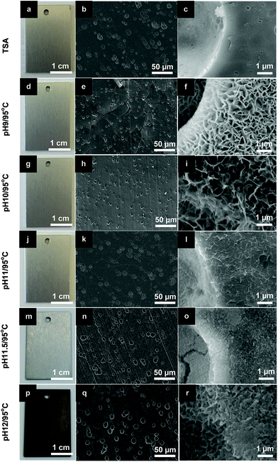 | ||
| Fig. 2 Photographs and SEM images of (a–c) TSA (blank sample) and LDH sealed TSA at 95 °C under different pH conditions: (d–f) pH 9; (g–i) pH 10; (j–l) pH 11; (m–o) pH 11.5 and (p–r) pH 12. | ||
The XRD patterns of the samples are shown in ESI Fig. S1 (please see ESI†). For LDH layers typically grown for 30 min, as described in Section 2.3, the thickness of the layers is too low and results in peak broadening with lower peak intensity (ESI Fig. S1a†). But longer growth runs for 5 hours were also prepared as model experiments to improve the XRD signal and help on the discussion of differences between samples (ESI Fig. S1a†). The XRD analyses illustrate the presence of crystalline LDH structures with typical Li–Al-LDH-NO3 reflections (002), (101) and (004) at 9.88° (d(002) = 8.95 Å), 20.21° (d(101) = 4.39 Å) and 23.18° (d(004) = 3.84 Å), respectively, for samples prepared at pH 9/95 °C and pH 10/95 °C (ESI Fig. S1a†), in accordance with previous reports.27–29 For more alkaline aqueous baths, above 10 pH, in ambient atmosphere conditions, –OH− and –CO32− anions are the predominant species15,30 and compete with –NO3− to preferentially form LDH-OH or LDH-CO3 structures.31,32 At pH 11 the peak positions for reflections (002), (101) and (004) shift to higher angles at 11.62° (d(002) = 7.6 Å), 20.40° (d(101) = 4.35 Å) and 23.32° (d(004) = 3.81 Å), respectively. This is ascribed to LDH-OH/CO3 signature, showing that LDH are intercalated with –OH−/CO32−, with similar crystallinity than LDH-NO3 structures.24,30–32 Other secondary phases such as Li2CO3 (ref. 27) and Al(OH)3 (ref. 24) were also detected.
To evaluate the influence of LDH sealing prepared at different pH on the final corrosion behavior of samples, EIS measurements up to one week of immersion in 0.05 M NaCl aqueous solution were performed (Fig. 3). Among the several pH conditions, by far the best sealing and protection performance were obtained for the pH 11/95 °C condition. After 1 week of immersion (Fig. 3b), this sample demonstrates the highest modulus of impedance values in the whole frequency range, more than one order of magnitude higher than all the other pH conditions, and almost three orders of magnitude higher than the TSA (blank sample). It is also interesting to note that the sample prepared at pH 11.5 also increased the resistance of the porous layer in comparison to the pH below 11. One possible reason could be attributed to the higher performance of LDH-OH/CO3 type materials, formed above pH 10, over the LDH-NO3 ones. But this is far too difficult to further understand the mechanisms based only on EIS analyses. Moreover, the crystallinity of the LDH structures seems not playing a relevant role in the resistance of the layers since all prepared samples have similar crystallinity. The most plausible reason for the superior properties of the LDH sealing at pH 11/95 °C is related to the lower layer thickness which is free of cracks combined with a very uniform densely packed at nano-scale LDH flakes (Fig. 2k and l).
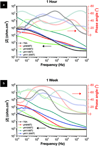 | ||
| Fig. 3 Bode and phase angle plots of the LDH layers prepared at different pH after (a) 1 hour and (b) 1 week immersion in 0.05 M NaCl solution. | ||
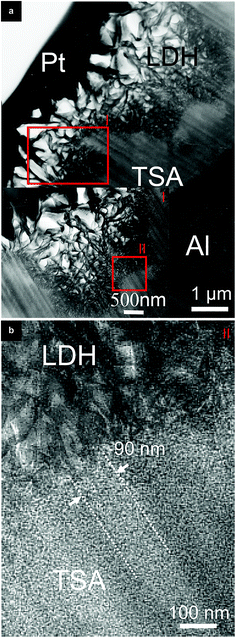
TEM analyses (Fig. 4) of the cross-sectional view of the layers sheds some light on the LDH flakes structure inside the nano-sized porosity of the TSA layer. LDH flakes hierarchically organized in size are seen, bigger on the surface (Fig. 4a) and with decreased size down to nanometer scale partially inside the pores (Fig. 4b). Images give clues for flakes of ∼40 nm been growing in an entangled form partially inside the pores of ∼90 nm together with a partial conversion of the anodic layer into LDH structures. Although, it is not clear in Fig. 4b to which extend in deep inside the pore the LDH growth occurred.
Results point out that the high anti-corrosive performance of the pH 11/95 °C sample might not be only due to the good barrier properties of the densely packed LDH top layer of ∼1 μm, but also from the LDH nano-flakes partially sealing the pores.
3.2. Active sealing with VOx intercalated LDH
The best growth condition for LDH (pH 11/95 °C) found in previous Section 3.1 provides good barrier properties. This method of LDH preparation was further improved to include active corrosion. To this end, inhibitor was incorporated in LDH nano-flakes by preparing LDH intercalated with VOx, LDH-VOx.ESI Fig. S2a and b† present the low magnification TEM images of LDH-OH/CO3 and LDH-VOx samples showing very uniform LDH layers (easily seen at higher magnification in the corresponding inset images). The respective EDX spectra presented in ESI Fig. S2c and d† clearly highlight the presence of the vanadium in the LDH-VOx samples, as expected. Moreover, to show that the VOx species were intercalated in the LDH galleries and not adsorbed on its surface, diffraction patterns were analyzed (inset images of ESI Fig. S2a and b†). Both materials have diffraction patterns with well-defined rings typical of LDH structures.33 The d-spacings calculated from the rings diameters of (hkl) type planes corresponding to the c-stacking direction, related to LDH galleries height, increased with the intercalation of the VOx species from d(442) = 1.76 Å (LDH-OH/CO3) to d(442) = 1.86 Å (LDH-VOx), due to the increased radius of the anion or/and decrease in charge density in relation to OH−/CO3.2–31 The respective XRD patterns of the samples (ESI Fig. S3†) corroborate the TEM analyses, a slight shift of 0.08° of the (002) peak to lower angles was observed when VOx species were intercalated in LDH, in agreement with other works published by the authors.13,14 These results highlight that the VOx species are inside the host LDH galleries and a successful intercalation process was achieved.28,31,34
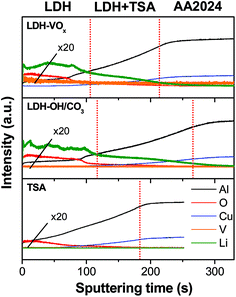
GDOES depth profiles of the samples shown in Fig. 5, indicate that the lithium and vanadium signals are observed preferentially both at the TSA surface and also deeper, within the pores, giving clue that might almost reach the oxide/metal interface. These results corroborate the TEM observations (Fig. 4) and provide evidences for a partially sealing in depth with LDH structures carrying active corrosion inhibiting species inside the pores for an improved synergetic corrosion protection: barrier properties and active inhibition.
3.3. Benchmarking studies of sealing processes
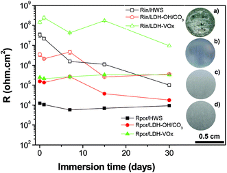
As referred in the Introduction section, HWS is the state-of-the-art sealing applied in aeronautics. HWS is used here as a reference to compare with the new LDH-based sealing processes. Photographs and SEM images of the Li–Al-LDH samples (ESI Fig. S4†) show that the clean surface appearance and the flake-like structures are very similar to the reference and are in good agreement with the previous report.15The EIS measurements, for long immersion time up to 1 month, in Fig. 6 show that the VOx species have a positive effect on the barrier properties of the TSA layer, both resistances of the inner and porous layers illustrated in Fig. 1 are higher than those for LDH-OH/CO3. Previous results obtained on Zn–Al-LDH system are consistent with the present ones.13 Moreover, the LDH sealings have higher performance when compared with the HWS ones, Rin and Rpor of the LDH-based layers are generally higher than the HWS values over time Fig. 6.
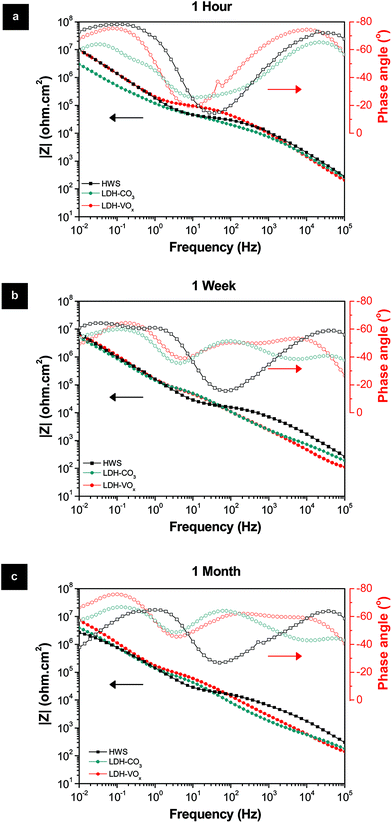 | ||
| Fig. 6 Bode and phase angle plots of the HWS and LDH-based layers after (a) 1 hour, (b) 1 week and (c) 1 month immersion in 0.05 M NaCl solution. | ||
The superior Rpor values of the LDH-based layers over the HWS layers are explained by the existence of an extra time constant (Fig. 7). This additional relaxation process at higher frequencies for the LDH-based layers can be ascribed to the LDH top layer (por 1). The second time constant at middle frequencies is related to the barrier properties of the conversion layer within the porous part of TSA (Fig. 7). In the case of HWS, only one well defined time constant responsible for the sealed porous layer is observed, since there is no formation of such an extra layer on the top. The respective equivalent circuits are presented in Fig. 7b and d.
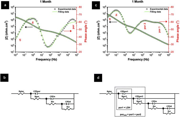 | ||
| Fig. 7 Fitting data of the sealing layers for 1 month of immersion in 0.05 M NaCl and respective equivalent circuits: (a, b) HWS and (c, d) LDH-VOx. | ||
The evolution of the layer parameters for different systems is presented in Fig. 8. The resistance of the pore for the porous layer sealed with LDH is represented by the sum of two components described above. The resistance of the sealed porous layer is the highest for LDH-VOx followed by the one with nitrate LDH, suggesting in both cases an efficient LDH mediated blocking of ionic transport through the layer. Even more importantly, the resistance of the inner barrier layer at the metal interface is also highest and the most stable for the inhibitor containing LDH sealed sample. This layer is the last barrier for the corrosive species before reaching the metal surface and thus plays a determining role in the total performance of the system.
It is well-know that hot-water sealing treatments promote the hydration of the porous aluminium oxide, porous and barrier layers, to produce a crystalline needle-like hydrate phase, know as boehmite, which filled in the pores.35 Similar aqueous treatments supplemented with inorganic salts, such as those used here, will have a synergetic effect of having formed a mixture of boehmite phase and new precipitated LDH phases, also with morphology resemble needle structures, growing inside the pores to form higher packed sealings. This clearly explains the superior resistance of the inner barrier layer of the LDH sealings over the HWS ones (Fig. 8). On the other hand, the higher performance of LDH-VOx compared to LDH-OH/CO3 is not completely comprehensible, with different contributions being valid. For LDH-VOx samples, the extra intercalation step in water might contribute to further hydration of the barrier layer. Also, the vanadate species that were not intercalated in the LDH, and are available in solution, can be absorbed on top of the barrier layer contributing to the increase of its resistance (Fig. 8). Other possibility is assigned to the self-healing effect of the LDH sealing, i.e. release of the VOx inhibitor and covalent bonding to the metal surface upon starting of corrosion events.22 Eventhough, this is less reasonable at significant extend, because if true EIS data of Fig. 8 would show an increase of the resistance of the inner barrier layer mediated by the release of the inhibitor. Contrarily, a decreasing behavior of resistance is observed, in line with previous observations.14 This is in agreement with the EIS of Fig. 7c and d, showing that the resistance of the charge transfer (Rct) activities at the metal surface is still very high after 1 month of immersion in NaCl. This means that the corrosion kinetic is very low, with far too small corrosion events able to activate the self-healing effect.
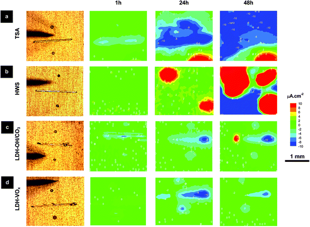
Therefore, SVET localized analyses at artificial defects were accomplished to further understand the corrosion processes and kinetics. The SVET observations shown in Fig. 9 corroborate the EIS data. Strong anodic activity is seen in the blank (TSA) and reference (HWS) samples after 24 h immersion in 0.05 M NaCl, but not in the LDH treated samples. Additionally, LDH-VOx samples have higher anticorrosive properties than LDH-OH/CO3 ones. This is in good agreement with previous results for Zn–Al-LDH sealing.13 After 48 h of immersion, only weak cathodic activity in LDH-VOx samples was seen, while stronger anodic and cathodic activities were detected in the LDH-OH/CO3 samples. Also note that corrosion activity was restricted only to the artificial defects in case of LDH-OH/CO3 and LDH-VOx samples, while for TSA and HWS samples, with time, corrosion propagated also to the initially intact areas. For immersion times up to 48 h, a fluctuating cathodic activity (increase and decrease) measured on the LDH-VOx samples was detected, as shown for 24 h and 48 h acquisition times, that can be assigned to the controlled release of the inhibiting VOx species on demand (triggered by the corrosion activities). This effect can be easily seen in Fig. S4,† where an increase of the cathodic activity means that insufficient amount of VOx species are released, but after a resting period of around 24 h (activation of the LDH release process), the VOx species begins to be released followed by a reduction of the cathodic activity in the next 24 h. This corroborates recent published studies on the corrosion inhibition of AA2024-T3. It was found that VOx species inhibit cathodic kinetics of AA2024-T3 corrosion in NaCl solutions36 upon formation of an adsorbed passivation layer21 that suppresses the oxygen reduction.22
Moreover, the observed behavior also shows that the VOx species are inside the LDH galleries, otherwise, if they were adsorbed on the LDH walls, no activation time would be seen, the VOx species would start to protect the surface immediately when the onset of the first activities occurred at the scribe, after 6 h of immersion in the corrosive solution (ESI Fig. S5†).
Further investigation on the VOx species release and delivery to the defect side was done with Raman and EDX analyses (ESI Fig. S6 and S7†). LDH-VOx samples were studied before and after immersion in 0.05 M NaCl for 48 h, the same conditions as used for SVET tests.
Raman phase analyses were used to decipher which VOx species play a key role in the corrosion inhibition in the defects. Optical images of the samples, before (ESI Fig. S6a†) and after immersion (ESI Fig. S6c†), show that the scribe becomes dark with corrosion products after immersion in the NaCl corrosive medium. So, VOx species are expected to be released from LDH structure and diffuse through the electrolyte towards the scribe where they suppress corrosion to some extent, accordingly to SVET data (Fig. 9 and ESI Fig. S5†). As shown by Ribeiro et al., monovanadates (VO4−), monoprotonated monovanadates (HVO42−) and divanadates (V2O74−) present a broad band in the range of 790–880 cm−1, while diprotonated monovanadates (H2VO4−) and cyclic tetravanadates (V4O124−) have typically a sharp asymmetric band centered at 945 cm−1.37 All spectra of ESI Fig. S6c and d† show the presence of a broad band in the 790–880 cm−1 range with a sharp peak centered at 824 cm−1 that is overlapped with sharp asymmetric band at 942 cm−1. This data shows that a mixture of monovanadate species might play a role in the corrosion protection,15 perhaps with a predominance of H2VO4− or V4O124− species due to a more intense band signal. For the sample exposed for 48 h to NaCl, the signal of the VOx species on the scribe is below the detection limit, cannot be seen. Signals can only be seen on the LDH-VOx layers, before and after immersion (ESI Fig. S6b and d†).
EDX analyses shown in ESI Fig. S7† were performed to verify the presence of vanadium (V) in the defects, and give complementary information to the obtained Raman data. ESI Fig. S7a and c† correspond to the SEM micrographs of the scribe before and after immersion, respectively. The EDX line acquisition conducted across the scribe shows that the V Kα-shell signal of the VOx species (at 4.95 keV) was detected on the LDH-VOx layer, but not on the scribe, as expected (ESI Fig. S7b†). After 48 h immersion in NaCl, the scribe (inset of ESI Fig. S7c†) had a different appearance compared with a fresh scribe (inset of ESI Fig. S7a†). The scribe exposed to NaCl contains deposited corrosion products and exposed Cu-containing intermetallics. It is of interest to see that the localized EDX analysis on the intermetallic particle (red line, ESI Fig. S7d†) shows strong Kα-shell signals at 5.89, 6.37 and 8.04 keV for Mn, Fe and Cu, respectively, together with the appearance of the V signal at 4.95 keV. According to recent studies on the corrosion inhibition of AA2024-T3,22,36 Al–Cu–Mn–Fe–Si precipitates tend to be cathodic sites. These findings are consistent with our results, where VOx species, particularly V4O124− species,22 were shown to be deposited on Al–Cu–Mn–Fe–Si cathodic precipitates upon corrosion in NaCl.
3.4. LDH sealing at lower temperature
As shown in previous sections, Li–Al-LDH structures can be grown in conditions similar to those for HWS (temperature of the bath of 95 °C) and the new LDH sealing layers rendered higher anticorrosive performance than the current commercially used HWS. In an attempt to make the Li–Al-LDH-OH/CO3 sealing more competitive, less energy consuming “green” sealing process, further studies were carried out at lower temperature down to the room temperature.No significant effect of the temperature is seen in the appearance (Fig. 10a, d, g and j) and morphology of the LDH layers (Fig. 10b–l). An important highlight is here drawn to the LDH sealing prepared at room temperature (pH 11/25 °C). No visible layer covering the TSA was formed, but the pores are totally filled by LDH nanoflakes with morphology close to those obtained at higher bath temperatures. Moreover, the crystallinity of the LDH flakes was not significantly changed with temperature decrease. The XRD patterns of ESI Fig. S8.† show that the main LDH peaks of (002), (101) and (004) are slightly sharper at the highest temperature, proving that samples prepared under this condition have the highest crystallinity.
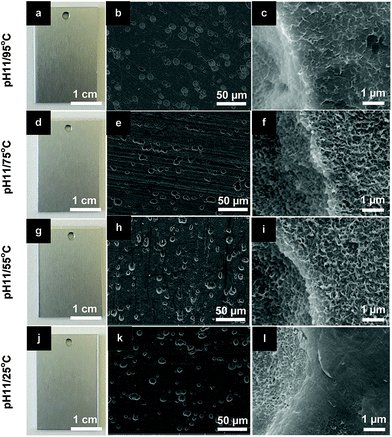 | ||
| Fig. 10 Photographs and SEM images of LDH-OH/CO3 sealed TSA at pH 11 for different bath temperatures: (a–c) 95 °C; (d–f) 75 °C; (g–i) 55 °C; (j–l) 25 °C. | ||
Several works have shown that is thermodynamically possible to have Li–Al-LDH layers formed and stabilized at room temperature, and they have a fast growth kinetics with low activation energies.15,16 Buchheit et al. has shown a Li-conversion layers grown at 25 °C with similar morphology as those shown here.15 Recent findings reported by Visser et al.16 have depicted Li–Al-LDH conversion layers being formed in defects of AA2024-T3 painted with Li salt containing formulation. The LDH structures were formed during a neutral salt spray test (ASTM B-117) close to room temperature (35 °C). Under these conditions, Li-based pigments dispersed in the coating were leached and reacted with the Al3+ of the aluminum surface to form LDH structures.16
The corrosion protection properties of the samples treated at lower temperatures were studied by EIS (Fig. 11). These results demonstrate that the corrosion protection properties of the systems obtained at reasonably low temperatures are still quite acceptable. Even after one week of immersion test, the low frequency impedance remains at relatively high values for all the systems treated in full temperature range. For one system a well-defined time constant at about 1 Hz is clearly observed which is responsible for the inner barrier layer. The resistance of this layer after a week of immersion is still above 1 Mohm cm2 confirming a remarkable corrosion protection especially considering the fact that the sealing treatment was performed at room temperature conditions. Overall, it is confirmed that the LDH sealing at higher temperatures increases the barrier properties of the TSA film, both porous and inner parts, but not significantly. Such a subtle improvement in the protective properties does not justify significant increase of costs associated with high temperature treatment. Li–Al-LDH-OH/CO3 grown on TSA-2024 at room temperature provides corrosion protection comparable to that offered by standard HWS procedure (Fig. 6b). The versatility of Li–Al-LDHs and room temperature preparation conditions sets its technological parameters window closer to industrial acceptance and exploitation with high cost operation savings expected.
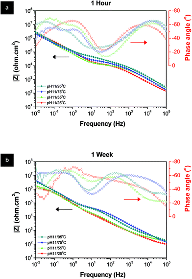 | ||
| Fig. 11 Bode and phase angle plots of the LDH-OH/CO3 layers prepared at different temperatures after (a) 1 hour and (b) 1 week immersion in 0.05 M NaCl solution. | ||
4. Conclusions
The active protective sealing of TSA anodic layer was achieved via treatment of anodized AA2024-T3 in Li-containing baths. Li–Al-LDH is formed in the porous layer as well as on the surface of the anodic film. LDH layers hosting vanadate corrosion inhibiting anions are used as “smart” reservoirs for the controlled-release of the corrosion inhibitor via anion-exchange process.The Li–Al-LDH-VOx active layers loaded with VOx corrosion inhibiting species showed strong synergetic anti-corrosion performance, both barrier and active protection were identified, with overall performance better than the Li–Al-LDH-OH/CO3 reference. EIS data for LDH-OH/CO3 and LDH-VOx sealed TSA show an increased barrier properties and improved stability of the dense oxide layer at the metal-porous oxide interface when compared to HWS treatment, while SVET shows an increased active inhibition of corrosion processes in artificial scribe defects.
The Li-based sealing was also achieved at close to room temperature condition which is significantly lower than conventionally used temperatures for HWS. The low temperature treatments allow formation of LDH structures in the TSA layer and confer reasonably high corrosion resistance. The low temperature sealing has an important advantage over HWS or other sealing approaches, which require temperatures close to water boiling point.
Acknowledgements
This work has received funding from the European Union's Horizon 2020 research and innovation programme under grant agreement no. 645676 project MULTISURF. Dr M. Mohedano is grateful to MICINN (Spain) for financial support via Proyecto Retos Jovenes Investigadores MAT2015-73355-JIN. Dr S. V. Lamaka acknowledges the financial support of Alexander von Humboldt Foundation via Experienced Researcher Grant. Dr J. Tedim thanks FCT for the researcher grant IF/00347/2013. This work was developed in the scope of the project CICECO – Aveiro Institute of Materials, POCI-01-0145-FEDER-007679 (Ref. FCT UID/CTM/50011/2013), financed by national funds through the FCT/MEC and when applicable co-financed by FEDER under the PT2020 Partnership Agreement. Dr D. Mata would like to thank Dr Nico Scharnagl for the Raman scientific discussions. Authors acknowledge Mr Maksim Starykevich for carrying out the GDOES analyses.Notes and references
- E. Eichinger, Met. Finish., 1997, 95, 36–41 CrossRef CAS.
- M. Curioni, P. Skeldon, E. Koroleva, G. E. Thompson and J. Ferguson, J. Electrochem. Soc., 2009, 156, C147–C153 CrossRef CAS.
- M. García-Rubio, M. P. de Lara, P. Ocón, S. Diekhoff, M. Beneke, A. Lavía and I. García, Electrochim. Acta, 2009, 54, 4789–4800 CrossRef.
- W. J. Wittke, Met. Finish., 1989, 87, 24–26 CAS.
- G. A. Dorsey, J. Electrochem. Soc., 1966, 113, 169–172 CrossRef CAS.
- V. R. Capelossi, M. Poelman, I. Recloux, R. P. B. Hernandez, H. G. de Melo and M. G. Olivier, Electrochim. Acta, 2014, 124, 69–79 CrossRef CAS.
- G. Boisier, N. Pébère, C. Druez, M. Villatte and S. Suel, J. Electrochem. Soc., 2008, 155, C521–C529 CrossRef CAS.
- Y. Zuo, P.-H. Zhao and J.-M. Zhao, Surf. Coat. Technol., 2003, 166, 237–242 CrossRef CAS.
- R. L. Twite and G. P. Bierwagen, Prog. Org. Coat., 1998, 33, 91–100 CrossRef CAS.
- J. Tedim, M. L. Zheludkevich, A. N. Salak, A. Lisenkov and M. G. S. Ferreira, J. Mater. Chem., 2011, 21, 15464–15470 RSC.
- K. A. Yasakau, J. Tedim, M. L. Zheludkevich and M. G. S. Ferreira, Corrosion, 2013, 70, 436–445 CrossRef.
- J. Tedim, M. L. Zheludkevich, A. C. Bastos, A. N. Salak, A. D. Lisenkov and M. G. S. Ferreira, Electrochim. Acta, 2014, 117, 164–171 CrossRef CAS.
- B. Kuznetsov, M. Serdechnova, J. Tedim, M. Starykevich, S. Kallip, M. P. Oliveira, T. Hack, S. Nixon, M. G. S. Ferreira and M. L. Zheludkevich, RSC Adv., 2016, 6, 13942–13952 RSC.
- M. Serdechnova, M. Mohedano, B. Kuznetsov, C. L. Mendis, M. Starykevich, S. Karpushenkov, J. Tedim, M. G. S. Ferreira, C. Blawert and M. L. Zheludkevich, J. Electrochem. Soc., 2017, 164, C36–C45 CrossRef CAS.
- R. G. Buchheit, M. D. Bode and G. E. Stoner, Corrosion, 1994, 50, 205–214 CrossRef CAS.
- P. Visser, Y. Liu, H. Terryn and J. M. C. Mol, J. Coat. Technol. Res., 2016, 13, 557–566 CrossRef CAS.
- P. Visser, Y. Liu, X. Zhou, T. Hashimoto, G. E. Thompson, S. B. Lyon, L. G. J. van der Ven, A. J. M. C. Mol and H. A. Terryn, Faraday Discuss., 2015, 180, 511–526 RSC.
- A. M. Fogg, J. S. Dunn and D. O'Hare, Chem. Mater., 1998, 10, 356–360 CrossRef CAS.
- P. K. Dutta and M. Puri, J. Phys. Chem., 1989, 93, 376–381 CrossRef CAS.
- L. Lei, F. Millange, R. I. Walton and D. O'Hare, J. Mater. Chem., 2000, 10, 1881–1886 RSC.
- M. Iannuzzi and G. S. Frankel, Corros. Sci., 2007, 49, 2371–2391 CrossRef CAS.
- K. D. Ralston, S. Chrisanti, T. L. Young and R. G. Buchheit, J. Electrochem. Soc., 2008, 155, C350–C359 CrossRef CAS.
- J.-H. Syu, J.-Y. Uan, M.-C. Lin and Z.-Y. Lin, Corros. Sci., 2013, 68, 238–248 CrossRef CAS.
- Y. Zhang, J. Liu, Y. Li, M. Yu, S. Li and B. Xue, J. Coat. Technol. Res., 2015, 12, 595–601 CrossRef CAS.
- G. Boisier, A. Lamure, N. Pébère, N. Portail and M. Villatte, Surf. Coat. Technol., 2009, 203, 3420–3426 CrossRef CAS.
- M. García-Rubio, P. Ocón, A. Climent-Font, R. W. Smith, M. Curioni, G. E. Thompson, P. Skeldon, A. Lavía and I. García, Corros. Sci., 2009, 51, 2034–2042 CrossRef.
- K. Okada, F. Matsushita and S. Hayashi, Clay Miner., 1997, 32, 299–305 CAS.
- I. C. Chisem and W. Jones, J. Mater. Chem., 1994, 4, 1737–1744 RSC.
- I. Sissoko, E. T. Iyagba, R. Sahai and P. Biloen, J. Solid State Chem., 1985, 60, 283–288 CrossRef CAS.
- M.-C. Lin, F.-T. Chang and J.-Y. Uan, J. Mater. Chem., 2010, 20, 6524–6530 RSC.
- J. D. Phillips and L. J. Vandeperre, J. Nucl. Mater., 2011, 416, 225–229 CrossRef CAS.
- M. Serdechnova, A. N. Salak, F. S. Barbosa, D. E. L. Vieira, J. Tedim, M. L. Zheludkevich and M. G. S. Ferreira, J. Solid State Chem., 2016, 233, 158–165 CrossRef CAS.
- S. Britto, A. V. Radha, N. Ravishankar and P. V. Kamath, Solid State Sci., 2007, 9, 279–286 CrossRef CAS.
- V. Rives and M. A. Angeles Ulibarri, Coord. Chem. Rev., 1999, 181, 61–120 CrossRef CAS.
- J. W. Diggle, T. C. Downie and C. Goulding, Chem. Rev., 1969, 69, 365–405 CrossRef CAS.
- P. Campestrini, E. P. M. van Westing, H. W. van Rooijen and J. H. W. de Wit, Corros. Sci., 2000, 42, 1853–1861 CrossRef CAS.
- A. C. F. Ribeiro, A. J. M. Valente, V. M. M. Lobo, E. F. G. Azevedo, A. M. Amado, A. M. A. da Costa, M. L. S. Ramos and H. D. Burrows, J. Mol. Struct., 2004, 703, 93–101 CrossRef CAS.
Footnote |
| † Electronic supplementary information (ESI) available. See DOI: 10.1039/c7ra05593e |
| This journal is © The Royal Society of Chemistry 2017 |

