 Open Access Article
Creative Commons Attribution 3.0 Unported Licence
Effect of flake size on the mechanical properties of graphene aerogels prepared by freeze casting†
Weiwei Gao *a,
Nifang Zhaob,
Weiquan Yaoa,
Zhen Xua,
Hao Baib and
Chao Gao
 a
a
aMOE Key Laboratory of Macromolecular Synthesis and Functionalization, Department of Polymer Science and Engineering, Key Laboratory of Adsorption and Separation Materials & Technologies of Zhejiang Province, Zhejiang University, Hangzhou 310027, China. E-mail: wwgao@zju.edu.cn
bState Key Laboratory of Chemical Engineering, College of Chemical and Biological Engineering, Zhejiang University, Hangzhou 310027, China
First published on 3rd July 2017
Abstract
Aerogels enable a wide range of potential applications owing to their ultralow density, superelasticity, high specific surface area, energy-absorbability and so on. However, it is usually difficult to precisely control their mechanical performance, which largely hinders their applications. Here, we prepared anisotropic graphene aerogels assembled with flakes having different sizes ranging from sub-micron to ∼80 μm by the freeze casting technique, using ice as a template to assembling graphene oxide (GO) sheets into 3-dimensional (3D) aerogels. We found that graphene flake size has a profound effect on the mechanical performance of the assembled graphene aerogels, particularly their strength, modulus and fatigue resistance under compression. Larger flakes had stronger interaction when assembled, which made them more resistant to slipping between adjacent flakes during deformation. As a result, the graphene aerogel with larger flake size showed both higher strength and fatigue resistance. Our research provides a new way of controlling the mechanical properties of graphene aerogel by only adjusting the intrinsic properties of the flakes, e.g., size, without crosslinking agent or co-assembly with other materials as in previous studies.
Introduction
Graphene aerogel has aroused increasing attention from interdisciplinary fields for its wide potential applications such as soft electronic sensors, energy absorbers, oil-removal materials, and so on.1–19 Its mechanical properties, including strength, robustness, and fatigue resistance are highly crucial for those applications.1,7,8,20–25 From a mechanical point of view, graphene aerogels are highly porous, lightweight and thus usually fragile. As a result, it is still a grand challenge to fabricate mechanically strong and robust graphene aerogels, especially at a large scale with low cost.Many techniques including chemical vapor deposition (CVD),26 sol–gel transition,27 hydrothermal method,28–30 and freeze-casting1,4,6,31,32 have been developed to improve the mechanical performance of graphene aerogels, usually by controlling their multiscale architecture at both the macro and micro scales. However, it remains difficult to translate the unique intrinsic mechanical properties of single GO flake into a 3-dimensional (3D) macroscopic aerogel. This is due to the low controllability over structure during fabrication of macroscopic networks, especially when building blocks with a high aspect ratio are used. Although some progresses have been made in this direction, there is still no systematic study linking the properties of the building block (graphene oxide flake) and its assembly (graphene aerogel), which requires tailoring architecture at multiple scales.
Here, we present the effect of flake size on mechanical properties of graphene aerogel. A series of elastomeric graphene aerogels with flakes having a wide range of size, from sub-micron to ∼80 μm, were prepared by the freeze casting technique. It showed that the graphene flake size has a profound effect on the mechanical performance of the assembled graphene aerogels, particularly their strength, modulus and fatigue resistance under compression. Larger flakes had stronger interaction with adjacent ones when assembled, making them more resistant to slip during deformation. As a result, the graphene aerogel assembled by larger flake size showed both higher strength and fatigue resistance. Different from previous efforts in tailoring graphene aerogels' mechanical properties where crosslinking agents and co-assembly with other materials were usually employed, we controlled their properties by only the flake size. By adjusting the intrinsic properties of the flakes, particularly their size, our research provides a new way of controlling the mechanical properties of graphene aerogel, which is crucial for its multifunctionality and applications.
Materials and methods
Materials
Graphene oxide (GO) suspension with ∼80 μm in size was received from Hangzhou Gaoxi Technology Co. Ltd. (http://www.gaoxitech.com) (Zhejiang, China). Aqueous Poly (vinyl alcohol) (PVA, Mw = 20![[thin space (1/6-em)]](https://www.rsc.org/images/entities/char_2009.gif) 500, 99%) was purchased from Aladdin Chemistry Co., Ltd, China.
500, 99%) was purchased from Aladdin Chemistry Co., Ltd, China.
Preparation of graphene oxide precursor suspension
GO with ∼80 μm in size was sonicated for different amount of time with high energy to break down. After sonication for 3, 5, and 20 minutes, the GO flake size was reduced to ∼50 μm, ∼20 μm, and ∼1 μm, respectively. The concentrated GO suspensions of 10 mg ml−1 were obtained by centrifugation. PVA solution (10 mg ml−1) was added to the GO suspension. The ratio of GO![[thin space (1/6-em)]](https://www.rsc.org/images/entities/char_2009.gif) :
:![[thin space (1/6-em)]](https://www.rsc.org/images/entities/char_2009.gif) PVA was kept at 1
PVA was kept at 1![[thin space (1/6-em)]](https://www.rsc.org/images/entities/char_2009.gif) :
:![[thin space (1/6-em)]](https://www.rsc.org/images/entities/char_2009.gif) 1 in weight.
1 in weight.
Preparation of graphene oxide aerogels
Graphene oxide aerogels were fabricated by the unidirectional freeze casting method. The precursor suspension (GO![[thin space (1/6-em)]](https://www.rsc.org/images/entities/char_2009.gif) :
:![[thin space (1/6-em)]](https://www.rsc.org/images/entities/char_2009.gif) PVA = 5
PVA = 5![[thin space (1/6-em)]](https://www.rsc.org/images/entities/char_2009.gif) :
:![[thin space (1/6-em)]](https://www.rsc.org/images/entities/char_2009.gif) 5 mg ml−1) was poured into a square tube and then frozen at three typical temperatures of −196 °C (Liquid Nitrogen, LN), −90 °C, and −50 °C. After the precursor suspension was frozen entirely, the sample was tapped out of the mold and freeze–dried for more than 48 h at −80 °C with Freeze dryer under 0.05 mbar pressure (Labconco 8811, Kansas City, USA). Finally, the graphene aerogels were reduced by thermal treatment at 800 °C for 2 h in a 5% H2/95% Ar mixed gas.
5 mg ml−1) was poured into a square tube and then frozen at three typical temperatures of −196 °C (Liquid Nitrogen, LN), −90 °C, and −50 °C. After the precursor suspension was frozen entirely, the sample was tapped out of the mold and freeze–dried for more than 48 h at −80 °C with Freeze dryer under 0.05 mbar pressure (Labconco 8811, Kansas City, USA). Finally, the graphene aerogels were reduced by thermal treatment at 800 °C for 2 h in a 5% H2/95% Ar mixed gas.
Characterizations
GO flake size was checked using over 150 flakes by scanning electron microscopy (SEM) images, obtained by Hitachi S-3700 at an acceleration voltage of 10 kV in secondary electron mode. SEM samples were prepared by drop casting of diluted GO suspension on the silicon substrates. Mechanical properties of the prepared graphene aerogels were investigated in the compressive/tensile mode by an electronic universal testing machine (UTM2102, ShenZhen Suns Technology Stock Co., Ltd, China).Results and discussion
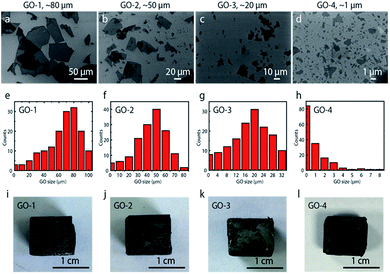
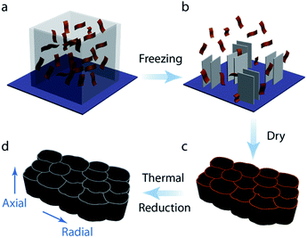
Fig. 1a–d shows SEM images of graphene oxide (GO) flakes with different sizes. The small GO was fabricated by sonicating commercial large GO flake. The flake size was properly controlled by the sonication power and time.6 SEM images show that large GO flakes were successfully broken down by our sonication method. The initial flake size was ∼80 μm, and reduced to ∼50 μm, ∼20 μm and ∼1 μm after proper treatment, which are defined as GO-1 (∼80 μm), GO-2 (∼50 μm), GO-3 (∼20 μm), and GO-4 (∼1 μm), respectively. The GO flake size was measured by SEM technique. The size distribution of the treated GO flakes was summarized respectively in Fig. 1e–h, based on the SEM image analysis of over 150 flakes with more than 5 different locations. Fig. 1i–l show the optical images of graphene aerogel assembled with different sized GO flakes. All the aerogels look similar in appearance.The fabrication route of graphene aerogels with different flake sizes was illustrated in Fig. 2.33,34 Firstly, the water suspension with GO flakes were prepared by dispersing and dissolving GO and PVA into water. The ratio of GO![[thin space (1/6-em)]](https://www.rsc.org/images/entities/char_2009.gif) :
:![[thin space (1/6-em)]](https://www.rsc.org/images/entities/char_2009.gif) PVA was kept as 1
PVA was kept as 1![[thin space (1/6-em)]](https://www.rsc.org/images/entities/char_2009.gif) :
:![[thin space (1/6-em)]](https://www.rsc.org/images/entities/char_2009.gif) 1 in weight (5
1 in weight (5![[thin space (1/6-em)]](https://www.rsc.org/images/entities/char_2009.gif) :
:![[thin space (1/6-em)]](https://www.rsc.org/images/entities/char_2009.gif) 5 mg ml−1). PVA was used to adjust the suspension viscosity for freeze casting.35,36 Previous studies have shown that viscosity is a crucial parameter in freeze casting affecting the architecture and properties of the final graphene aerogel.37 Secondly, the prepared GO suspensions with different flake size were cast into square Teflon molds placed on the copper rod which is the cold source. The suspension was unidirectionally frozen by decreasing the temperature of the copper rod at a controlled cooling rate. When completely frozen, the samples were tapped out of the mold and freeze–dried for more than 48 hours at −90 °C with 1 Pa pressure (Freeze Dryer 8, Labconco, USA). Reduced anisotropic graphene oxide aerogels were realized by thermal treatment (2 hours at 800 °C) in a 5% H2/95% Ar atmosphere in a tubular oven.
5 mg ml−1). PVA was used to adjust the suspension viscosity for freeze casting.35,36 Previous studies have shown that viscosity is a crucial parameter in freeze casting affecting the architecture and properties of the final graphene aerogel.37 Secondly, the prepared GO suspensions with different flake size were cast into square Teflon molds placed on the copper rod which is the cold source. The suspension was unidirectionally frozen by decreasing the temperature of the copper rod at a controlled cooling rate. When completely frozen, the samples were tapped out of the mold and freeze–dried for more than 48 hours at −90 °C with 1 Pa pressure (Freeze Dryer 8, Labconco, USA). Reduced anisotropic graphene oxide aerogels were realized by thermal treatment (2 hours at 800 °C) in a 5% H2/95% Ar atmosphere in a tubular oven.
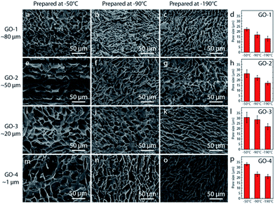
Fig. 3 shows the typical microstructure of graphene oxide aerogel with GO flake size ranging from sub-micron to ∼80 μm. Three typical freezing temperature of LN, −90 °C, and −50 °C were chosen for each GO flake size to systematically investigate the temperature effect on the formation of porous structure. During freeze casting process, ice crystals grow in aqueous phase when graphene oxide flakes are ejected from the moving ice front and aligned between the ice crystals, leading to the formation of continuous 3D network.4,6,31 Subsequently, the ice crystal is sublimated after freeze drying, leaving a stable free-standing 3D network. The freezing speed usually manipulated the microstructure of graphene aerogel,33,34,38–40 with lower speed resulting in aerogel with larger pore size. Besides, the suspension viscosity also has strong effect on the microstructure: higher viscosity usually leads to smaller pores in the final porous structure. In order to investigate the effect of GO flake size on the mechanical performance, PVA solution was added into all the GO suspensions to improve the viscosity to ensure coherent micro-porous structure of all the prepared graphene aerogels. In Fig. 3, a similar lamellar structure with a honeycomb-like morphology was observed in the aerogels, which is consistent with previously reported carbon based aerogels fabricated by freeze drying.4,21 As decreasing the freezing temperature from −50 °C to LN, the pores became slightly smaller. For example, from ∼22 μm of −50 °C to ∼13 μm of LN for aerogel with largest flakes (GO-1) with highest viscosity. Besides, few change in pore size for the aerogels assembled with different sized GO flake, only ∼10 μm difference. By increasing the viscosity of all the GO suspensions, we controlled the final microstructure of all the prepared graphene aerogels. By minimizing the effect of microstructure,4 we were thus able to compare systematically the effect of flake size on the mechanical properties of the graphene aerogels.
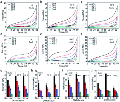
Fig. 4 systematically investigated the mechanical properties of the anisotropic graphene aerogels assembled with different sized GO flakes. Three freezing temperatures (LN, −90 °C, and −50 °C) were selected to manipulate the microstructure of the graphene aerogels. It was found that GO flake size had a profound effect on the mechanical properties. In the radial and axial directions of graphene aerogels, both strength and modulus decrease obviously when reducing the GO flake size. Meanwhile, strength values in the axial direction are higher than those of radial direction. For example, at the freezing temperature of −50 °C, the aerogels assembled with GO-1 (flake size: ∼80 μm), measured in the axial direction, exhibited a maximal strength (∼38 kPa) and modulus (∼34 kPa) at the strain of 80%, about 8 (strength) and 3 (modulus) times of that assembled with GO-4 (flake size: ∼1 μm). In the radial direction, the maximal strength and modulus (GO-1) are ∼29 kPa and ∼58 kPa, about 6 (strength) and 24 (modulus) times of graphene aerogels (GO-4). Moreover, graphene aerogels in the radial direction show better compression recovery behaviour, they can fully recover from large strain. For the graphene aerogels assembled with the same flake size but at different freezing temperature, the difference in mechanical properties is negligible, which could be attributed to their similar microstructure.4,6,31 Besides, the stretch properties of anisotropic graphene aerogels were studied in Fig. S1.† Both strength and modulus in axial direction are higher than those of radial direction in all the aerogels. However, aerogels in radial direction possess larger elongation at break.
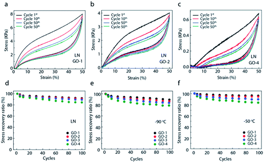
In order to investigate the fatigue resistance, the cyclic compression recovery performance of graphene aerogels was studied.32 Fig. 5 shows the cyclic stress–strain curves of graphene aerogels with different GO flake sizes at freezing temperature of LN, −90 °C, and −50 °C, respectively. With 50% strain, the aerogels assembled with large GO-1 flakes only experience a slight reduction in height and still remain over 92% of maximal stress after 100 compression cycles. In contrast, the aerogels with small GO flakes, especially GO-4 (sub-micron) flakes, show relatively poor mechanical performance including lower strength and modulus. Even under applied 50% strain, the aerogel can only recover to 80% of its original height and just leave 80% of stress after 100 compression cycles.
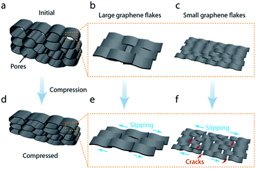
Fig. 6 shows the GO flake deformation mechanism of the aerogel wall composed of flakes with different size during compression. According to the SEM results, our graphene aerogels assembled with different sized GO flakes exhibited similar microstructure and inner morphology, with a narrow pore size distribution limited to 10 μm. Besides, all the aerogels looked similar in appearance in Fig. 1i–l. In principle, these aerogels should exhibit similar mechanical properties based on the previous reports.4,6,31 However, significant difference in mechanical properties were found among our aerogels. Aerogel assembled with large GO flakes had excellent mechanical properties, including higher compressive strength and modulus, as well as good anti-fatigue property during cyclic compression. Based on our study, micro-defects from the pore wall assembled with GO flakes contributed to such significant difference in mechanical performance. Following our special procedure, two separated aerogels with the same microstructure were assembled with large and small GO flakes, respectively. The pore wall constructed by large GO, especially ultra-large size GO flakes, has less defects. Large flakes display stronger interaction with adjacent ones to resist against deformation, usually resulting in ‘slipping’. In contrast, the assembly with small size GO usually takes more flakes than that of large flakes, and thus more overlap joints of GO flakes in pore wall, which are easy to crack as they have weaker inter-flake conjunctions during deformation. Our study shows how the intrinsic properties of the building blocks, i.e., GO flake size, could affect the mechanical properties of the macroscopic 3D assembly, i.e., graphene aerogel.
Conclusion
In conclusion, we have prepared a series of anisotropic graphene aerogels with different GO flake size ranging from sub-micron to ∼80 μm by the freeze casting technique, using ice as a template in assembling GO flakes into 3D aerogels. We increased the suspension viscosity to generate similar microstructures in the final graphene aerogels, which made it possible to minimize the effect of microstructure on the aerogels' mechanical properties. The aerogels with similar microstructure should show similar mechanical properties as predicted in literature. However, we found that GO flake size, in addition to the microstructure, also has a profound effect on the mechanical performance of the assembled graphene aerogels, particularly their strength, modulus and fatigue resistance under compression. Large flakes had stronger interaction when assembled, which made it more resistant to slip between adjacent flakes during deformation. As a result, the graphene aerogel with larger flake size showed both higher strength and fatigue resistance. By adjusting the intrinsic properties of the flakes, specifically their size, our research provides a new way of controlling the mechanical properties of graphene aerogel, which is crucial for its multifunctional applications.Acknowledgements
This work was supported by the National Natural Science Foundation of China (No. 51603183, 21325417, 51533008, 51603182), the Fundamental Research Funds for the Central Universities (No. 2017QNA4036, 2017XZZX008-006), and National Key R&D Program of China (Grant No. 2016YFA0200200). The ‘1000 Youth Talents Plan’ of China.References
- H. Sun, Z. Xu and C. Gao, Adv. Mater., 2013, 25, 2554–2560 CrossRef CAS PubMed.
- Z. Li, Z. Liu, H. Sun and C. Gao, Chem. Rev., 2015, 115, 7046–7117 CrossRef CAS PubMed.
- K. Shehzad, Y. Xu, C. Gao and X. Duan, Chem. Soc. Rev., 2016, 45, 5541–5588 RSC.
- L. Qiu, J. Z. Liu, S. L. Chang, Y. Wu and D. Li, Nat. Commun., 2012, 3, 1241 CrossRef PubMed.
- Y. Wu, N. Yi, L. Huang, T. Zhang, S. Fang, H. Chang, N. Li, J. Oh, J. A. Lee, M. Kozlov, A. C. Chipara, H. Terrones, P. Xiao, G. Long, Y. Huang, F. Zhang, L. Zhang, X. Lepro, C. Haines, M. D. Lima, N. P. Lopez, L. P. Rajukumar, A. L. Elias, S. Feng, S. J. Kim, N. T. Narayanan, P. M. Ajayan, M. Terrones, A. Aliev, P. Chu, Z. Zhang, R. H. Baughman and Y. Chen, Nat. Commun., 2015, 6, 6141 CrossRef CAS PubMed.
- N. Ni, S. Barg, E. Garcia-Tunon, F. Macul Perez, M. Miranda, C. Lu, C. Mattevi and E. Saiz, Sci. Rep., 2015, 5, 13712 CrossRef PubMed.
- Z. Lei, Y. Yan, J. Feng, J. Wu, G. Huang, X. Li, W. Xing and L. Zhao, RSC Adv., 2015, 5, 25650–25656 RSC.
- S. Liao, T. Zhai and H. Xia, J. Mater. Chem. A, 2016, 4, 1068–1077 CAS.
- X. Zhang, P. Liu, Y. Duan, M. Jiang and J. Zhang, RSC Adv., 2017, 7, 16467–16473 RSC.
- M. Yu, W. Qiu, F. Wang, T. Zhai, P. Fang, X. Lu and Y. Tong, J. Mater. Chem. A, 2015, 3, 15792–15823 CAS.
- H. Chen, F. Guo, Y. Liu, T. Huang, B. Zheng, N. Ananth, Z. Xu, W. Gao and C. Gao, Adv. Mater., 2017, 27, 1605958 CrossRef PubMed.
- H. Chang, J. Qin, P. Xiao, Y. Yang, T. Zhang, Y. Ma, Y. Huang and Y. Chen, Adv. Mater., 2016, 28, 3504–3509 CrossRef CAS PubMed.
- Y. Wu, M. Gong, M.-C. Lin, C. Yuan, M. Angell, L. Huang, D.-Y. Wang, X. Zhang, J. Yang, B.-J. Hwang and H. Dai, Adv. Mater., 2016, 28, 9218–9222 CrossRef CAS PubMed.
- H. Bi, X. Xie, K. Yin, Y. Zhou, S. Wan, L. He, F. Xu, F. Banhart, L. Sun and R. S. Ruoff, Adv. Funct. Mater., 2012, 22, 4421–4425 CrossRef CAS.
- S. Wan, J. Peng, L. Jiang and Q. Cheng, Adv. Mater., 2016, 28, 7862–7898 CrossRef CAS PubMed.
- Y. Zhang, S. Gong, Q. Zhang, P. Ming, S. Wan, J. Peng, L. Jiang and Q. Cheng, Chem. Soc. Rev., 2016, 45, 2378–2395 RSC.
- K. Chen, X. Tang, Y. Yue, H. Zhao and L. Guo, ACS Nano, 2016, 10, 4816–4827 CrossRef CAS PubMed.
- X. Gui, J. Wei, K. Wang, A. Cao, H. Zhu, Y. Jia, Q. Shu and D. Wu, Adv. Mater., 2010, 22, 617–621 CrossRef CAS PubMed.
- Q. Peng, Y. Li, X. He, X. Gui, Y. Shang, C. Wang, C. Wang, W. Zhao, S. Du, E. Shi, P. Li, D. Wu and A. Cao, Adv. Mater., 2014, 26, 3241–3247 CrossRef CAS PubMed.
- T. Zhang, H. Chang, Y. Wu, P. Xiao, N. Yi, Y. Lu, Y. Ma, Y. Huang, K. Zhao, X.-Q. Yan, Z.-B. Liu, J.-G. Tian and Y. Chen, Nat. Photonics, 2015, 9, 471–476 CrossRef CAS.
- X. Xu, Q. Zhang, Y. Yu, W. Chen, H. Hu and H. Li, Adv. Mater., 2016, 28, 9223–9230 CrossRef CAS PubMed.
- C. Bao, S. Bi, H. Zhang, J. Zhao, P. Wang, C. Y. Yue and J. Yang, J. Mater. Chem. A, 2016, 4, 9437–9446 CAS.
- H. Hu, Z. Zhao, W. Wan, Y. Gogotsi and J. Qiu, Adv. Mater., 2013, 25, 2219–2223 CrossRef CAS PubMed.
- L. Qiu, D. Liu, Y. Wang, C. Cheng, K. Zhou, J. Ding, V. T. Truong and D. Li, Adv. Mater., 2014, 26, 3333–3337 CrossRef CAS PubMed.
- L. Qiu, M. Bulut Coskun, Y. Tang, J. Z. Liu, T. Alan, J. Ding, V.-T. Truong and D. Li, Adv. Mater., 2016, 28, 194–200 CrossRef CAS PubMed.
- Z. Chen, W. Ren, L. Gao, B. Liu, S. Pei and H.-M. Cheng, Nat. Mater., 2011, 10, 424–428 CrossRef CAS PubMed.
- M. A. Worsley, P. J. Pauzauskie, T. Y. Olson, J. Biener, J. H. Satcher and T. F. Baumann, J. Am. Chem. Soc., 2010, 132, 14067–14069 CrossRef CAS PubMed.
- Y. Li, J. Chen, L. Huang, C. Li, J.-D. Hong and G. Shi, Adv. Mater., 2014, 26, 4789–4793 CrossRef CAS PubMed.
- H. Hu, Z. Zhao, W. Wan, Y. Gogotsi and J. Qiu, Adv. Mater., 2013, 25, 2219–2223 CrossRef CAS PubMed.
- Y. Xu, K. Sheng, C. Li and G. Shi, ACS Nano, 2010, 4, 4324–4330 CrossRef CAS PubMed.
- S. Barg, F. M. Perez, N. Ni, P. do Vale Pereira, R. C. Maher, E. Garcia-Tuñon, S. Eslava, S. Agnoli, C. Mattevi and E. Saiz, Nat. Commun., 2014, 5, 4328 CAS.
- H. L. Gao, Y. B. Zhu, L. B. Mao, F. C. Wang, X. S. Luo, Y. Y. Liu, Y. Lu, Z. Pan, J. Ge, W. Shen, Y. R. Zheng, L. Xu, L. J. Wang, W. H. Xu, H. A. Wu and S. H. Yu, Nat. Commun., 2016, 7, 12920 CrossRef CAS PubMed.
- S. Deville, E. Saiz, R. K. Nalla and A. P. Tomsia, Science, 2006, 311, 515–518 CrossRef CAS PubMed.
- H. Bai, Y. Chen, B. Delattre, A. P. Tomsia and R. O. Ritchie, Sci. Adv., 2015, 1, e1500849 Search PubMed.
- H. Bai, C. Li, X. Wang and G. Shi, Chem. Commun., 2010, 46, 2376–2378 RSC.
- R. Verdejo, M. M. Bernal, L. J. Romasanta and M. A. Lopez-Manchado, J. Mater. Chem., 2011, 21, 3301–3310 RSC.
- C. Zhu, T. Y.-J. Han, E. B. Duoss, A. M. Golobic, J. D. Kuntz, C. M. Spadaccini and M. A. Worsley, Nat. Commun., 2015, 6, 6962 CrossRef CAS PubMed.
- H. Bai, F. Walsh, B. Gludovatz, B. Delattre, C. Huang, Y. Chen, A. P. Tomsia and R. O. Ritchie, Adv. Mater., 2016, 28, 50–56 CrossRef CAS PubMed.
- N. Zhao, M. Yang, Q. Zhao, W. Gao, T. Xie and H. Bai, ACS Nano, 2017, 11, 4777–4784 CrossRef CAS PubMed.
- M. Yang, N. Zhao, Y. Cui, W. Gao, Q. Zhao, C. Gao, H. Bai and T. Xie, ACS Nano, 2017 DOI:10.1021/acsnano.7b01815.
Footnote |
| † Electronic supplementary information (ESI) available. See DOI: 10.1039/c7ra05557a |
| This journal is © The Royal Society of Chemistry 2017 |

