 Open Access Article
Carbon nanofiber/poly(tetrahydro[1,4]dioxino[2,3-b]thieno[3,4-e][1,4]dioxine) binder-free composite redox-active electrode for electrochemical energy storage applications
Deniz Yiğit *a,
Furkan Soysalb,
Tuğba Güngörc,
Burhanettin Çiçekb and
Mustafa Güllü*a
aAnkara University, Faculty of Science, Department of Chemistry, Besevler, 06100, Ankara, Turkey. E-mail: dyigit@science.ankara.edu.tr; gullu@ankara.edu.tr
bAnkara University, Faculty of Engineering, Department of Chemical Engineering, Besevler, 06100, Ankara, Turkey
cÇanakkale Onsekiz Mart University, Faculty of Science and Arts, Department of Chemistry, 17100, Çanakkale, Turkey
First published on 25th August 2017
Abstract
We report the preparation and supercapacitive properties of a novel composite electrode material based on carbon nanofiber (CNF) and poly(tetrahydro[1,4]dioxino[2,3-b]thieno[3,4-e][1,4]dioxine) (PTDTD) for electrochemical energy storage applications. The CNF/PTDTD composite electrode was directly prepared by electrodeposition of PTDTD on the CNF coated substrate without any binder or conductive additives. The symmetric solid-state supercapacitor device was assembled by using these CNF/PTDTD composite electrodes. In addition, CNF/CNF and CNF/poly(3,4-ethylenedioxythiophene) (PEDOT) symmetric supercapacitor devices were also fabricated to make a detailed performance comparison. The electrochemical characteristics of all supercapacitor devices were comprehensively evaluated by CV, GCD and EIS measurements. The CNF/PTDTD composite electrodes delivered a maximum specific capacitance of 332 F g−1, energy density of 166 W h kg−1, power density of 4.9 kW kg−1 and an excellent cycling stability with 89% capacitance retention after 12![[thin space (1/6-em)]](https://www.rsc.org/images/entities/char_2009.gif) 500 cycles at 2 mA cm−2 current density while CNF/PEDOT electrodes were able to reach a specific capacitance of 254 F g−1, energy density of 128.8 W h kg−1 and power density of 5.45 kW kg−1 in those supercapacitor devices. These results confirmed that PTDTD has significant potential to be a good alternative redox-active material and CNF/PTDTD composite structure is a promising candidate for supercapacitor applications.
500 cycles at 2 mA cm−2 current density while CNF/PEDOT electrodes were able to reach a specific capacitance of 254 F g−1, energy density of 128.8 W h kg−1 and power density of 5.45 kW kg−1 in those supercapacitor devices. These results confirmed that PTDTD has significant potential to be a good alternative redox-active material and CNF/PTDTD composite structure is a promising candidate for supercapacitor applications.
1. Introduction
Supercapacitors, commonly known as electrochemical double-layer capacitors (EDLCs) or ultracapacitors, have become a promising approach for electrical energy storage over the last decade. Recently, they have attracted a great deal of attention due to the rapid developments in portable, flexible and wearable electronic device technologies. Supercapacitors fill the range between traditional dielectric capacitors and primary or secondary batteries in terms of their energy (∼5 W h kg−1) and power densities (∼15 kW kg−1).1 They also have prominent advantages such as short charging/discharging time, high storage efficiency, long-term cycling life and eco-friendliness when compared with conventional dielectric capacitors.2Unlike traditional dielectric capacitors, electrochemical, morphological and mechanical features of electrode materials play a major role on capacitive performance of a supercapacitor device.3 Namely, electrical conductivity, internal resistance, thickness, surface porosity and durability of electro-active materials strongly affect the charge storage ability of a supercapacitor. Hence, the great majority of academic and commercial endeavors in supercapacitor research have devoted to the development of novel electrode materials up to the present.4,5
Carbon-based materials and π-conjugated conducting polymers have been widely employed as electrode materials because of their extraordinary electronic and mechanical properties.6–9 To date, various carbonaceous structures like carbon nanotubes (CNTs),10 carbon nanofibers (CNFs),11 graphenes12 and carbon aerogels13 have been extensively examined as suitable electrode materials due to their highly active surface area and porosity, high charge mobility, excellent chemical and thermal stability. Among these carbon-based structures, CNFs have been considered as promising electrode materials for advanced energy storage devices owing to the fact that they have higher surface area, porosity and electrical conductivity and lower fabrication cost than the others.14 A more porous network facilitates ion diffusions by offering plentiful and efficient pathways in order to store more electrical charges. This feature makes CNFs attractive materials for a wide range of supercapacitor applications. Generally, carbon-based electrode materials involve non-faradaic mechanism for charge storage, which is known as electrochemical double-layer phenomenon.15 In other words, they weakly store the energy electrostatically at the electrode material/electrolyte interface by means of a fast ion sorption/desorption process based entirely on physical interactions. As a result of this, the electrochemical double-layer capacitors (EDLCs) can provide limited charge storage capacity although they have desired advantages such as highly porous surface structures, rapid ion kinetics, excellent electrochemical, chemical and thermal stabilities.16 On the other hand, the ion diffusion or movement rate in the porous network of carbon-based electrode materials is usually restricted since it is unavoidable to use a polymeric binder in the preparation of electrode materials for many solid-state EDLC applications.17 The presence of a binder strikingly increases internal resistance and gives rise to loss of energy density. So, there are still major challenges to integrate all carbonaceous structures into many supercapacitor applications including high-power performance electronic devices due to the above-mentioned concrete disadvantages.
Charge storage mechanism of π-conjugated conducting polymers, on the other hand, involves typically a fast and reversible redox reaction process across the electrode/electrolyte interface as well as electrostatic ion sorption/desorption.18,19 These faradaic redox processes, called as pseudocapacitive phenomenon, in π-conjugated conducting polymers result in much higher specific capacitance and power density values than EDLCs. They exhibit excellent electronic conductivity, better mechanical stability and fast switching responses between their redox states in addition to lower fabrication cost, ease of modification and good environmental stability.20 Moreover, almost all conducting polymer-based redox-active materials can be directly deposited on many substrates by electropolymerization without the use of any polymeric binder, which is considered as a covetable advantage for practical energy storage applications compared to carbonaceous materials.
Polyanilines (PANI),21 polypyrroles (PPy),22 polythiophenes (PTh),23 polycarbazoles (PCbz)24 and poly(3,4-ethylenedioxythiophene) (PEDOT)25 have been intensely utilized as redox-active electrode materials for many pseudocapacitor applications, where satisfactory specific capacitance values were observed in the range of 210–640 F g−1. On the other hand, most polymeric redox-active electrode materials suffer from poor cycling stability. This mechanical instability occurs due to the swelling and shrinking of the polymer chain during the charge/discharge process.26 To overcome this problem and improve long-term cycling performance of polymer-based electrode materials, various solutions have been offered until now. The composite electrode of a conducting polymer with a carbon-based material can be considered as the most commonly used concept among different approaches. Numerous composite or hybrid electrode materials have been prepared by combining the advantages of carbon-based materials (CNTs, CNFs and graphenes) with various conducting polymers derivatives (PTh, PPy and PEDOT) and maximum specific capacitance values in the range of 45–482 F g−1 have been reported.27–30 Moreover, these composite electrode materials have exhibited better long-term cycling stabilities than those of solely conducting polymer-based electrodes because of synergistic performance contributed by each component. Therefore, the combination of conducting polymers with porous carbon-based materials possessing high surface area is a better looking strategy in order to create unique composite electrode materials with better electronic properties.
In this context, herein, we present preparation and symmetric solid-state pseudocapacitor application of a novel composite electrode material based on carbon nanofiber (CNF)/poly(2,3,4a,9a-tetrahydro[1,4]dioxino[2,3-b]thieno[3,4-e][1,4] dioxine) (PTDTD) for high-performance electrochemical energy storage devices. The novel conducting polymer derivative (PTDTD) used in composite electrode materials has been purposefully designed and synthesized and it includes additional fused 1,4-dioxane ring system compared to PEDOT. CNF was directly grown on stainless steel substrates by cold wall chemical vapor deposition (CVD) method. Then, PTDTD coated CNF composite electrode materials were prepared electrochemically by cyclic voltammetry technique without the use of any polymeric binder. Symmetric type solid-state pseudocapacitor cell was constructed with CNF/PTDTD composite redox-active electrode materials. Moreover, two different type symmetric supercapacitors consisting of only CNF electrodes and CNF/PEDOT composite electrodes were also fabricated in order to make an objective comparison of the effect of PTDTD redox-active layer on capacitive performance parameters. The supercapacitive behaviours of all symmetric solid-state supercapacitor cells were evaluated by cyclic voltammetry (CV), galvanostatic charge/discharge (GCD) and electrochemical impedance spectroscopy (EIS) techniques in two-electrode configurations and compared in detail.
2. Experimental section
Materials and instrumentation
All chemicals were purchased from Sigma-Aldrich and used without any further purification. Stainless steel (99.9%) obtained from a local manufacturer was directly used as a current collector substrate in dimensions of 10 mm width, 10 mm length and 0.4 mm thickness. The Ag/Ag+ pseudoreference silver wire was calibrated using Fc/Fc+ ferrocene redox couple standard (0.3 V versus silver wire). Lithium perchlorate (LiClO4) was dried at 85–90 °C for 10 h while acetonitrile (ACN) was fractionally distilled in the presence of P2O5 before the electrochemical studies. Diethyl 2.2′-thiodiacetate,31 diethyl 3,4-dihydroxythiophene-2,5-dicarboxylate (1)32 and 2,3-dichloro-1,4-dioxane (2)33 were synthesized according to previously reported procedures. An AbsoluteNano Sabre Tube Chemical Vapor Deposition (CVD) system was used to grow up carbon nanofiber (CNF) on the stainless steel substrate surface. 1H and 13C NMR spectra were recorded in CDCl3 at room temperature on a Varian-Mercury 400 MHz digital Fourier-transform (FT) NMR spectrometer with tetramethyl silane (TMS) as an internal standard. All chemical shifts are also given in ppm. To record mass spectra of the intermediate products and target monomer, an Agilent Technologies 6890N Network GC System/5975B VL MSD was used at an ionization potential (EI) of 70 eV. FTIR spectra were recorded with a PerkinElmer Spectrum 100 spectrometer. The morphological characterizations of CNF, CNF/PTDTD and CNF/PEDOT electrode materials were performed with a Zeiss Evo40 500 V to 30 kV scanning electron microscope (SEM). Elemental analyses of the novel monomers and their conducting polymers were conducted with a Leco CHNS-932 elemental analyser. A Princeton Applied Research PAR-2273 potentiostat/galvanostat and a Radiometer VoltaLab PST050 potentiostat/galvanostat-high voltage booster 100 V HVB100 were used for electrochemical performance studies of symmetric solid-state supercapacitor cells.Synthesis of the monomer (TDTD)
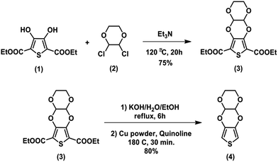
The electroactive target monomer, 2,3,4a,9a-tetrahydro[1,4]dioxino[2,3-b]thieno[3,4-e][1,4]dioxine (TDTD), was synthesized in three steps including nucleophilic substitution, hydrolysis and decarboxylation reactions according to previously reported synthetic method.34 The synthetic pathway for TDTD is briefly described in Scheme 1. The structural characterization of TDTD was carried out by FTIR, 1H NMR, 13C NMR, mass spectroscopy techniques and elemental analysis.Preparation of CNF, CNF/PTDTD and CNF/PEDOT electrode materials
CNF was directly synthesized on the stainless steel substrates by a cold wall Chemical Vapor Deposition (CVD) system. The CVD system basically consists of a quartz tubular reactor having 50 mm id, a DC power supply for resistive heating, a hot plate including steel fittings and highly doped silicon wafer and an infrared sensor for temperature control. Iron or any other catalyst coating on the substrate surface was found not to be needed since the growing of CNF was already carried out on a stainless steel substrate. All feed stream flow rates were controlled by mass flow controllers. The substrate was placed over the hot plate and kept under 100 sccm He/200 sccm H2 flow for 1 min at 700 °C in order to remove the oxide layer. Then, the temperature was set to 725 °C and CNFs were grown under 275 sccm He/200 sccm H2/25 sccm C2H2 flow. The stainless steel substrate was homogeneously coated by CNF in 2 min. The morphological properties of CNF electrode materials were determined with a SEM. Diameter distribution of CNF was also performed using JMicroVision: Image Analysis Toolbox.Both CNF/PTDTD and CNF/PEDOT composite redox-active electrode materials were prepared by electropolymerization of TDTD and EDOT on the surface of CNF coated substrate. Prior to electropolymerization studies, the cyclic voltammogram of TDTD was initially recorded in a 0.1 M LiClO4/ACN supporting electrolyte solution in order to investigate the electrochemical redox behavior of this novel thieno[3,4-e][1,4]dioxine derivative. Consisting of a three-electrode (Pt, Pt and Ag/Ag+) cell configuration, cyclic voltammetry study (CV) was performed by scanning the potential between 0.0 V and +2.0 V vs. Ag/Ag+ pseudoreference electrode at a scan rate of 150 mV s−1 under nitrogen atmosphere. TDTD exhibited a characteristic irreversible monomer oxidation peak at +1.85 V in the first cycle of anodic potential scanning. Following the monomer oxidation, PTDTD conducting polymer film rapidly formed on the platinum working electrode and reversible redox wave emerged with an increase in the current density. The reversible redox couples of PTDTD were centered at +1.14 V/+0.84 V after each successive oxidation/reduction cycle. PTDTD polymer films on the platinum surface was subjected to −0.5 V for 0.5 min to remove any trapped charge or dopant ions on the polymer chain. Then, it was rinsed with ACN and kept in an oven at 70 °C for 5 h. PTDTD polymeric material was characterized by FTIR and elemental analysis techniques. FTIR v/cm−1 3160, 3120 (aromatic C–H stretching), 2960, 2875 (aliphatic C–H stretching), 1650 (polyconjugation), 1485, 1381 (aromatic C![[double bond, length as m-dash]](https://www.rsc.org/images/entities/char_e001.gif) C stretching), 1155, 1093 (C–H in plane bending). Elemental analysis. Anal. calcd for (C8H6O4S)n: C, 48.23%; H, 3.53%. Found: C, 47.75%; H, 3.40%.
C stretching), 1155, 1093 (C–H in plane bending). Elemental analysis. Anal. calcd for (C8H6O4S)n: C, 48.23%; H, 3.53%. Found: C, 47.75%; H, 3.40%.
After the CV studies, CNF/PTDTD composite electrode materials were prepared by a cyclic voltammetry technique in the presence of 0.03 M monomer in 0.1 M LiClO4/ACN under a nitrogen atmosphere. The potensiodynamic electrodeposition studies were carried out using a typical three-electrode cell configuration including a CNF coated stainless steel working electrode, a stainless steel auxiliary electrode and Ag/Ag+ pseudoreference electrode. After coating of PTDTD layer, CNF/PTDTD composite electrode was rinsed with ACN in order to remove unreacted monomer residues and put in an oven at 65 °C for 5.5 h. The same procedure was applied for the fabrication of CNF/PEDOT composite electrodes. The morphological properties of CNF/PTDTD and CNF/PEDOT composite electrode materials were studied with a SEM in detail. The electroactive material mass for each composite electrode, sum of CNF and polymer masses loaded on stainless steel substrates, was determined using a microanalytical balance (Δm = ±0.001 mg) six times in a row. The average of the six weights was used as total active material mass in electrochemical performance measurements. The average active material masses of CNF/PEDOT and CNF/PTDTD composite electrodes were approximately 0.35 mg cm−2 and 0.38 mg cm−2, respectively.
Construction of all symmetric solid-state supercapacitor devices
Three symmetric solid-state supercapacitor cells were assembled with CNF, CNF/PTDTD and CNF/PEDOT electrode materials in this study. To construct supercapacitor devices, at first, the electrode materials were fully wetted with 0.5 M LiClO4/ACN supporting electrolyte solution. Thin separator paper soaked to 0.5 M LiClO4/ACN was carefully placed on the surface of one electrode. Then, the second electrode material was overlapped and assembled by sandwiching. Finally, the supercapacitor cell was hermetically sealed by means of wrapping with a thin paraffin band. The supercapacitor devices fabricated with CNF, CNF/PEDOT and CNF/PTDTD were symbolized as Device I, Device II and Device III, respectively. Both schematic representation and photographs of symmetric solid-state prototype supercapacitor device are given in Fig. 1.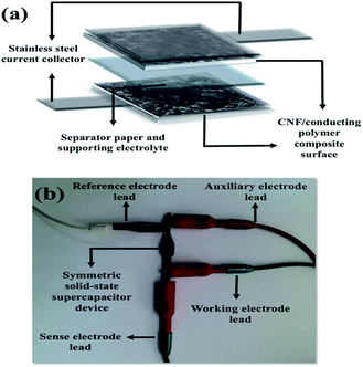 | ||
| Fig. 1 (a) Schematic representation of the symmetric type solid-state supercapacitor device; (b) photograph of the prototype solid-state supercapacitor device. | ||
Capacitive performance measurements
The supercapacitive performances of all electrode materials were evaluated with two-electrode system configuration under ambient conditions. In two-electrode cell setup, reference electrode was connected on the same side of auxiliary electrode. Cyclic voltammetry (CV), galvanostatic charge/discharge (GCD) and electrochemical impedance spectroscopy (EIS) techniques were employed for electrochemical performance tests. The current–potential profiles of supercapacitor devices were recorded using CV in the potential range of 0.0 V and 2.0 V at various scan rates (10, 25, 50, 100, 150, 250, 500 mV s−1). GCD performance tests were performed at constant current densities of 2, 4, 10, 15, 20 mA cm−2 in 0.0 V and 2.0 V potential range. Similarly, GCD technique was employed in order to perform the long-term cycling stability studies and GCD curves were recorded at 2 mA cm−2 constant current density between 0.0 V and 2.0 V over 12![[thin space (1/6-em)]](https://www.rsc.org/images/entities/char_2009.gif) 500 cycles. EIS measurements were conducted with a frequency range from 104 to 10−2 Hz and voltage amplitude of 5 mV rms at 0.0 V applied DC voltage.
500 cycles. EIS measurements were conducted with a frequency range from 104 to 10−2 Hz and voltage amplitude of 5 mV rms at 0.0 V applied DC voltage.
The gravimetric specific capacitance (Cspec, F g−1), energy density (E, W h kg−1) and power density (P, kW kg−1) values for all symmetric solid-state supercapacitor devices were calculated from GCD curves by using following equations:
| Cspec = (I × td)/(ΔV × mac) | (1) |
| E = [Cspec × (ΔV)2]/7.2 | (2) |
| P = (3600 × E)/td | (3) |
3. Results and discussion
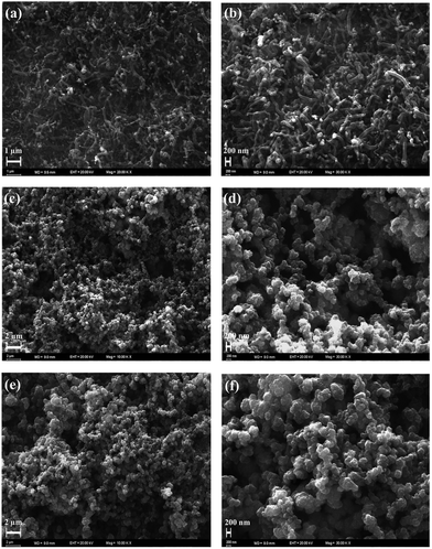
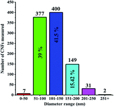
CNF was successfully grown onto the surface of stainless steel substrates by a typical cold wall chemical vapor deposition (CVD) system. Generally, iron or nickel based catalysts were required to be coated on substrates to produce CNF in CVD-based fabrication methods.35–37 In this study, CNF layer was directly grown without any iron or nickel catalyst because stainless steel substrates were already used on the production process of CNF active layer. This can be considered as a significant advantage since extra mass was not loaded on electrode materials. The morphological features of CNF coated substrates were probed by SEM. Being recorded at different magnifications, SEM images reveal that stainless steel surfaces were homogeneously covered by CNF layer, as evidently seen in Fig. 2a and b.CNF layer is expected to create a three-dimensional highly porous network for effective ion diffusions to store more electrical charges. Moreover, diameter distribution of CNF layer on the stainless steel substrates was obtained by measuring the diameters of about one thousand fibers with JMicroVision: Image Analysis Toolbox. According to the distribution analysis, more than 80% of CNFs are in the range of 51–150 nm while 15% of CNFs are in the 151–200 nm scale. The smaller diameters than 50 nm and greater diameters than 250 nm of CNFs correspond to only 0.93% of all measured samples. The diameter distribution for CNFs is given in Fig. 3.
Cyclic voltammetry (CV) was employed to investigate electrochemical properties of TDTD and its corresponding conducting polymer, PTDTD. As seen from Fig. 4a, TDTD exhibited an irreversible monomer oxidation peak at +1.85 V during the first cycle, while characteristic reversible redox waves were clearly observed at +1.14 V/+0.84 V for PTDTD with an increase in the current density. Single scan cyclic voltammogram was also recorded for PTDTD coated platinum electrode in a monomer free supporting electrolyte solution to evaluate its p- and n-doping characteristics. Yet, PTDTD showed only p-doping property with reversible redox couples at +1.15 V/+0.83 V vs. Ag wire pseudoreference electrode. In addition, similar CV studies were carried out under the same conditions for EDOT and PEDOT (Fig. 4b).
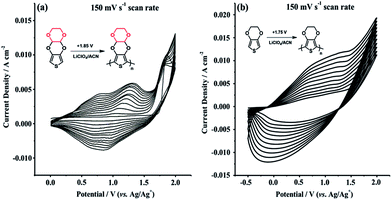 | ||
| Fig. 4 Repeated potential scan polymerization of (a) TDTD; (b) EDOT in 0.1 M LiClO4/ACN supporting electrolyte at a 150 mV s−1 scan rate. | ||
After electrochemical characterization of TDTD and PTDTD, PTDTD and PEDOT coated CNF composite electrode materials were prepared by cyclic voltammetry technique. The morphological characterizations of both CNF/PTDTD and CNF/PEDOT composite electrode materials were studied by SEM in detail. Fig. 2c–f clearly show that PTDTD and PEDOT conducting polymer films regularly formed across the CNF substrate surfaces after the electropolymerization. Additional fused 1,4-dioxane ring gives TDTD monomer a more planar structure compared with EDOT. This planarity effect allows longer growth conducting polymer chains on CNF layer during electropolymerization and provides a more regular and porous surface morphology to PTDTD redox-active network, as can be seen in Fig. 2c and e. This morphological property is thought to be an appropriate network for more effective ion diffusion pathways and enhance charge storage capacity of CNF/PTDTD composite electrode material.
Prior to supercapacitor performance studies of supercapacitor devices, the ideal working potential range was firstly determined by CV in a three-electrode cell configuration with the different potential scales at a scan rate of 150 mV s−1. The ideal current–potential (I–V) characteristics close to rectangular shape form were obtained in 0.0 V and 2.0 V potential window for CNF/PTDTD and CNF/PEDOT composite electrode materials. Therefore, the potential range between 0.0 V and 2.0 V was determined as ideal working potential scale for symmetric solid-state supercapacitor devices constructed with CNF, CNF/PTDTD and CNF/PEDOT electrodes.
For electrochemical performance tests, symmetric type three solid-state supercapacitor devices were assembled in a typical two-electrode configuration. CNF, CNF/PEDOT and CNF/PTDTD electrodes were used both as anode and cathode materials to construct Device I, Device II and Device III, respectively. A traditional two-electrode setup was especially chosen in all electrochemical performance measurements owing to its significant advantages. In contrast to three-electrode cell configuration, specific capacitance (Cspec), energy density (E) and power density (P) values in a symmetrical two-electrode cell are calculated for the entire supercapacitor cell where the potential difference applied to supercapacitor device is equally shared by each electrode material. Additionally, the potential of cathode material can be exactly controlled and measured in this system. Therefore, being performed with two-electrode device configuration, supercapacitor studies not only exhibit more realistic and objective results for capacitive performance evaluations, but also can be easily adapted for practical electrochemical energy storage applications.
CV studies were primarily carried out in 0.0 V to 2.0 V potential range in order to evaluate current–potential (I–V) profiles and charge/discharge behaviors of Device I, Device II and Device III. As shown in Fig. 5, Device I (CNF) showed a nearly rectangular I–V shaped whereas Device II (CNF/PEDOT) and Device III (CNF/PTDTD) exhibited deviations from rectangularity. These deviations observed in current–potential responses of Device II and Device III arise from faradaic reactions on the CNF/PEDOT and CNF/PTDTD redox-active surfaces. In addition to I–V profiles, the scan rate dependence of capacitive performance is another important property for supercapacitor applications. Generally, an ideal supercapacitor device is expected to keep its I–V profile shape as the sweep rate is gradually increased. To understand the effect of scan rate on the capacitive behavior, cyclic voltammograms were also recorded with various scan rates ranging from 10 to 500 mV s−1 for all symmetric solid-state supercapacitor devices.
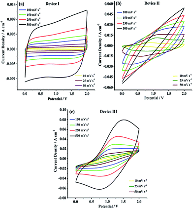 | ||
| Fig. 5 Cyclic voltammograms of (a) Device I (CNF); (b) Device II (CNF/PEDOT); (c) Device III (CNF/PTDTD) at different scan rates. | ||
As can be seen in Fig. 5a–c, Device I, Device II and Device III were able to keep their I–V profile shapes even at the highest scan rates. These responses mean that Device I (CNF) has an ideal non-faradaic capacitive behavior and charge/discharge characteristic while Device II (CNF/PEDOT) and Device III (CNF/PTDTD) display high-rate reversibility and stability during a faradaic charge/discharge process. On the other hand, it can be clearly seen synergistic pseudocapacitive effects of the PTDTD and PEDOT redox-active polymeric layers when CV curves are examined. The CV current densities of Device II and Device III are much higher than that of Device I under the same CV conditions. According to CV study results, it can be also said that Device III (CNF/PTDTD) has a superiority capacitive performance over Device II (CNF/PEDOT).
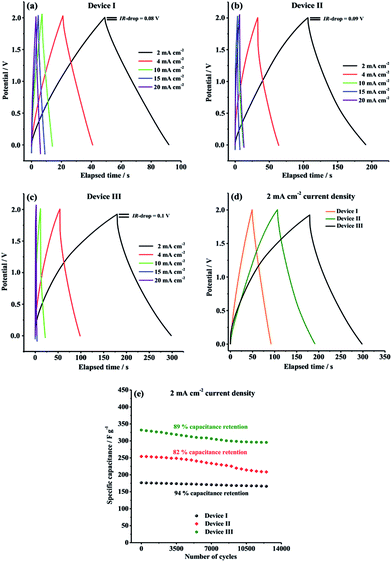
GCD characteristics of Device I, Device II and Device III were explored over the potential range of 0.0 V to 2.0 V in order to perform a more comprehensive supercapacitive performance evaluation. GCD measurements are essential in terms of calculation of crucial performance parameters such as specific capacitance (Cspec), energy density (E) and power density (P). As depicted in Fig. 6, all symmetric solid-state supercapacitor cells, Device I, Device II and Device III, exhibited almost symmetric triangular charging and discharging profiles at a constant current density of 2 mA cm−2, indicating that Device I had ideal capacitive behavior and Device II and Device III indicated good reversible faradaic redox reactions during charge/discharge cycles. Additionally, it is clearly seen that the ohmic drop (IR-drop) values are very small (0.08 V, 0.09 V and 0.1 V for Device I, Device II and Device III, respectively) at 2 mA cm−2 constant current density.
As seen in Table 1, both Device II (254.3 F g−1) and Device III (332 F g−1) delivered much higher specific capacitance than that of Device I (176.6 F g−1) at 2 mA cm−2 constant current density, which are compatible with the results obtained from CV curves. The considerable difference in the gravimetric capacitances is due to the presence of synergistic pseudocapacitance of PTDTD and PEDOT conducting polymer film layer on carbon nanofiber surfaces, as predicted. Compared to our previous supercapacitor studies with PTDTD, these new results obtained with CNF/PTDTD show a significant increase on capacitive performance by coating the substrate surface with carbon nanofiber template. CNF/PTDTD composite electrode material delivered much higher capacitance than that of PTDTD/PTDTD redox-active electrode material.34 This difference between capacitive performances can be directly correlated with the highly porous 3D morphology of carbon nanofiber network. Obviously, porous surface morphology of CNF substrate provided CNF/PTDTD composite electrode material to have more ion accessible hole to store electrolyte ions and, thus significantly enhanced its capacitive performance by facilitating faster ion diffusion or movement during faradaic redox processes. On the other hand, Device III (CNF/PTDTD) exhibited better charge storage performance than Device II (CNF/PEDOT) despite the lack of n-doping behaviour of PTDTD redox-active material (Fig. 6d). This reveals the achievement and feasibility of our molecular design approach to enhance supercapacitive performance of conducting polymer-based electrode materials.
| Supercapacitor device | Specific capacitance (Cspec) F g−1 | Energy density (E) W h kg−1 | Power density (P) kW kg−1 |
|---|---|---|---|
| Device I | 176.6 | 90.4 | 7.65 |
| Device II | 254.3 | 128.8 | 5.45 |
| Device III | 332 | 166 | 4.9 |
The satisfactory energy densities for Device I, Device II and Device III were obtained as summarized in Table 1. Device II (CNF/PEDOT) and Device III (CNF/PTDTD) delivered much higher energy densities than Device I (CNF) due to the extra pseudocapacitance effect of PEDOT and PTDTD redox-active layers, as expected. On the other side, the energy density value of Device III (CNF/PTDTD) is more as compared to that of Device II (CNF/PEDOT), reflecting a lower internal resistance or equivalent series resistance (ESR) of the CNF/PTDTD composite redox-active electrode material. The energy and power density values calculated from GCD curves endorse that both CNF/PTDTD and CNF/PEDOT composite electrodes exhibited fast and highly reversible ion transfer kinetics throughout charge and delivery cycles.
The GCD curves were also recorded with 4, 10, 15, 20 mA cm−2 constant current densities in order to evaluate the rate capability of CNF, CNF/PEDOT and CNF/PTDTD electrode materials. Generally, as the current density is increased, the charge storage ability of electrode materials apparently decreases owing to the limited ion diffusion rates. As can be seen in Fig. 6a–c, Device I, Device II and Device III were able to retain 80.8% (from 176.6 to 142.8 F g−1), 48.2% (from 254.3 to 122.7 F g−1) and 51% (from 332 to 169.6 F g−1) of their initial capacitive performances, respectively, when current density was increased from 2 mA cm−2 to 20 mA cm−2. This result proves that CNF electrode material has better charge/discharge rate capability than those of CNF/PEDOT and CNF/PTDTD composite electrode materials even at high current densities. The charge/discharge rate capabilities of CNF/PEDOT and CNF/PTDTD redox-active surfaces could tolerate the increases in the current density lesser than CNF, as expected, since faradaic redox reactions are restricted at high constant current densities.
In addition to specific capacitance, energy and power density values, long-term cycling stability is another crucial parameter for a practical application of supercapacitor. The cycling performance of our symmetric type solid-state supercapacitor devices were further evaluated by recording a typical GCD curve at 2 mA cm−2 constant current density between 0.0 V and 2.0 V for 12![[thin space (1/6-em)]](https://www.rsc.org/images/entities/char_2009.gif) 500 cycles and the results are comparatively given in Fig. 6e. As well known, conducting polymer redox-active electrode materials usually suffer poor cycling stability because of surface degradation of polymer network during charge/discharge process. According to Fig. 6e, Device I (CNF), Device II (CNF/PEDOT) and Device III (CNF/PTDTD) supercapacitor devices exhibited quite good cycling stabilities and managed to keep 94%, 82% and 89% of their initial capacitive performances, respectively, at the end of 12
500 cycles and the results are comparatively given in Fig. 6e. As well known, conducting polymer redox-active electrode materials usually suffer poor cycling stability because of surface degradation of polymer network during charge/discharge process. According to Fig. 6e, Device I (CNF), Device II (CNF/PEDOT) and Device III (CNF/PTDTD) supercapacitor devices exhibited quite good cycling stabilities and managed to keep 94%, 82% and 89% of their initial capacitive performances, respectively, at the end of 12![[thin space (1/6-em)]](https://www.rsc.org/images/entities/char_2009.gif) 500 cycles. In particular, the satisfactory capacitance retention values of Device II (CNF/PEDOT) and Device III (CNF/PTDTD) are mainly due to that carbon nanofiber substrate surface provides a supplementary mechanical flexibility to tolerate the volume changes and degradation caused by swelling and shrinking of the conducting polymer chain during the long-term charge/deliver cycling.
500 cycles. In particular, the satisfactory capacitance retention values of Device II (CNF/PEDOT) and Device III (CNF/PTDTD) are mainly due to that carbon nanofiber substrate surface provides a supplementary mechanical flexibility to tolerate the volume changes and degradation caused by swelling and shrinking of the conducting polymer chain during the long-term charge/deliver cycling.
The capacitive performance of symmetric supercapacitor device fabricated with CNF/PTDTD redox-active electrode materials was found to be comparable to various composite electrodes based on carbonaceous materials/PEDOT, previously reported (Table 2). These results reveal that the synthesis of novel conducting polymer derivatives could be beneficial strategy for preparation of effective composite redox-active electrodes with better supercapacitive performances.
| Composite electrode material | Specific capacitance (Cspec) | Operating voltage | Ref. |
|---|---|---|---|
| a MWCNT = Multiwalled Carbon Nano Tube, SWCNT = Singlewalled Carbon Nano Tube and CNF = Carbon Nano Fiber. | |||
| Carbon nano-onion/PEDOT | 96.47 F g−1 | 0.6 V | 38 |
| Carbon microspheres/PEDOT | 106 F g−1 at 0.1 mA cm−2 | 0.8 V | 39 |
| MWCNT/PEDOT | 13.2 F g−1 | 0.8 V | 40 |
| MWCNT/PEDOT | 235 F g−1 at 1.25 A g−1 | 0.9 V | 41 |
| SWCNT/PEDOT | 53 F g−1 at 1 A g−1 | 0.9 V | 42 |
| Activated carbon/PEDOT | 158 F g−1 at 2 mA cm−2 | 1.0 V | 43 |
| Carbon nano foam/PEDOT | 142.5 F g−1 at 1 mA cm−2 | 1.0 V | 44 |
| Commercial carbon/PEDOT | 134 F g−1 at 1.0 A g−1 | 1.0 V | 45 |
| MWCNT/graphene/PEDOT | 225 F g−1 at 0.1 A g−1 | 1.0 V | 46 |
| SWCNT/PEDOT | 133 F g−1 at 0.2 A g−1 | 1.0 V | 47 |
| CNF/PEDOT | 154.5 F g−1 at 1 mA cm−2 | 1.2 V | 48 |
| CNT/PEDOT | 159 F g−1 at 2 mA cm−2 | 1.5 V | 27 |
| Carbon cloth/PEDOT | 256 F g−1 at 0.8 A g−1 | 1.6 V | 49 |
| SWCNT/PEDOT | 244.2 F g−1 | 2.0 V | 50 |
| CNF/PEDOT | 254.3 F g−1 at 2 mA cm−2 | 2.0 V | This work |
| CNF/PTDTD | 332 F g−1 at 2 mA cm−2 | 2.0 V | This work |
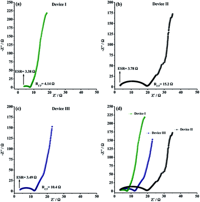
EIS measurements were finally carried out to analyze the internal resistance, ion diffusion rate and charge transfer kinetics of solid-state supercapacitor devices. As depicted in Fig. 7a–c, all EIS spectra, also known as Nyquist plots, exhibited a semi-circle pattern in the high-frequency region and a straight line portion in the low-frequency region, indicating an ideal supercapacitive behavior. The semi-circle pattern describes the electron transfer kinetics at the electrode–electrolyte interface while the straight line, defined as Warburg region, represents the ion diffusion step during charge/discharge process. In very high frequency region, equivalent series resistance (ESR) can be determined from the intercept point of Z′-axis and the starting point of semi-circle. ESR is generally described as the combined resistance including the ionic resistance of electrolyte, the electronic resistance of the electro-active material and the contact resistance between electrode material and current collector. The ESR values for Device I, Device II and Device III were determined to be 3.38 Ω, 3.78 Ω and 3.49 Ω, respectively (Fig. 7a–c). The ESR measurements showed that CNF/PEDOT and CNF/PTDTD composite electrode materials have satisfactory electronic properties for practical solid-state supercapacitor applications. RCT (charge transfer resistance) values were also obtained from Nyquist plots by the diameter of semi-circle pattern in the high-frequency region. Fig. 7a–c presented that Device II (CNF/PEDOT) (RCT = 15.2 Ω) and Device III (CNF/PTDTD) (RCT = 10.4 Ω) have higher than that of Device I (CNF) (RCT = 4.14 Ω) because of the interfacial resistance between the redox-active surface and electrolyte caused by additional charge transfer processes. On the other hand, Device III (CNF/PTDTD) exhibited a semi-circle pattern with a smaller radius than that of Device II (CNF/PEDOT). This impedance response indicates that PTDTD redox-active layer was uniformly coated on the CNF surface and the interaction between PTDTD polymer chain and CNF network interface was stronger compared with CNF/PEDOT composite structure. Also, the reflections of both ESR and RCT values on the capacitive performances of symmetric solid-state supercapacitor devices can be seen clearly on GCD tests. To give an example, Device III exhibited the higher energy density (166 W h kg−1) and the capacitance retention (89%) due to the relatively lower ESR and RCT values of CNF/PTDTD composite electrode material when compared to CNF/PEDOT.
In the low-frequency region, all Nyquist plots revealed vertical line toward the Z′-axis with an increase in the imaginary part (−Z′′), corresponding to ideal capacitive behavior for all symmetric type solid-state supercapacitor devices. The straight portion of Nyquist plot of Device I (CNF), Warburg region, is longer than those of Device II (CNF/PEDOT) and Device III (CNF/PTDTD). The disparate impedance behavior of Device I originates from relatively slow ion diffusion and longer diffusion path length in porous three-dimensional network of CNF electrode material. Device III (CNF/PTDTD) also exhibited much shorter Warburg zone than Device II (CNF/PEDOT), as shown in comparative Nyquist plots (Fig. 7d). The fast ion diffusion kinetics on Device III (CNF/PTDTD) can be attributed to the higher electrical conductivity and more sufficient diffusion pathways of CNF/PTDTD composite surface contributed by PTDTD conducting polymer layer. On the basis of the ESR and RCT measurements, it can be said that the electrochemical impedance spectroscopy results are in good agreement with cyclic voltammetry and galvanostatic charge/discharge data.
4. Conclusion
In summary, the novel CNF/PTDTD composite electrode material was prepared by electrodeposition of PTDTD polymeric layer on the CNF substrate and its supercapacitive properties were evaluated in detail. The CNF were grown via chemical vapor deposition technique on the stainless steel substrate and directly used as porous carbonaceous base substrate without any binder or conducting additives. This binder-free technique allowed the preparation of composite redox-active electrode materials with low equivalent series resistance (ESR). The symmetric supercapacitor device based on CNF/PTDTD composite electrode delivered a maximum specific capacitance of 332 F g−1, energy density of 166 W h kg−1, power density of 4.9 kW kg−1 and an good cycling stability with 89% capacitance retention even after 12![[thin space (1/6-em)]](https://www.rsc.org/images/entities/char_2009.gif) 500 cycles. The CNF/PTDTD composite electrode materials also exhibited better capacitive performance than that of CNF/PEDOT. The results revealed that PTDTD is a promising alternative redox-active material for supercapacitor applications. Moreover, the combination of PTDTD and CNF materials created versatile advantages for composite electrode material: (i) a large surface area for storing more electrical charges, (ii) a highly porous suitable surface morphology for faster ion diffusion and (iii) an extra mechanical strength to prevent polymeric surface degradation caused by swelling and shrinking during doping/undoping process.
500 cycles. The CNF/PTDTD composite electrode materials also exhibited better capacitive performance than that of CNF/PEDOT. The results revealed that PTDTD is a promising alternative redox-active material for supercapacitor applications. Moreover, the combination of PTDTD and CNF materials created versatile advantages for composite electrode material: (i) a large surface area for storing more electrical charges, (ii) a highly porous suitable surface morphology for faster ion diffusion and (iii) an extra mechanical strength to prevent polymeric surface degradation caused by swelling and shrinking during doping/undoping process.
Conflicts of interest
There are no conflicts to declare.Acknowledgements
Authors are grateful to the Scientific and Technological Research Council of Turkey (TÜBİTAK, Grant No: KBAG-114Z167 and Grant No: MAG-111M632) for generous financial support. D. Yiğit also thanks TÜBİTAK (KBAG-114Z167) for his postdoctoral scholarship.Notes and references
- M. M. Perez-Madrigal, F. Estrany, E. Armelin, D. D. Diaz and C. Aleman, J. Mater. Chem. A, 2006, 4, 1972 Search PubMed.
- A. G. Pandolfo and A. F. Hollenkamp, J. Power Sources, 2006, 157, 11 CrossRef CAS.
- J. Liu, J. G. Zhang, Z. Yang, J. P. Lemmon, C. Imhoff, G. L. Graff, L. Li, J. Hu, C. Wang, J. Xiao, G. Xia, V. V. Viswanathan, S. Baskaran, V. Sprenkle, X. Li, Y. Shao and B. Schwenzer, Adv. Funct. Mater., 2013, 23, 929 CrossRef CAS.
- J. Jensen, M. Hösel, A. L. Dyer and F. C. Krebs, Adv. Funct. Mater., 2015, 25, 2073 CrossRef CAS.
- C. C. Hu, K. H. Chang, M. C. Lin and Y. T. Wu, Nano Lett., 2006, 6(12), 2690 CrossRef CAS PubMed.
- Y. Yoo, S. Kim, B. Kim and W. Kim, J. Mater. Chem. A, 2015, 3, 11801 CAS.
- D. W. Lawrence, C. Tran, A. T. Mallajaysula, S. K. Doorn, A. Mahite, G. Grupta and V. Kalra, J. Mater. Chem. A, 2016, 4, 160 CAS.
- G. Wang, L. Zhang and J. Zhang, Chem. Soc. Rev., 2012, 41, 797 RSC.
- K. Wang, H. Wu, Y. Meng and Z. Wei, Small, 2014, 10(1), 14 CrossRef CAS PubMed.
- T. Chen and L. Dai, Mater. Today, 2013, 16(7–8), 272 CrossRef CAS.
- C. Ma, Y. Yu, Y. Li, J. Shi, Y. Song and L. Liu, J. Electrochem. Soc., 2014, 161(9), A1330 CrossRef CAS.
- J. Zhang, J. Xu and D. Zhang, J. Electrochem. Soc., 2016, 163(3), E83 CrossRef CAS.
- S. M. Jung, D. L. Mafra, C. Lin, H. Y. Jung and J. Kong, Nanoscale, 2015, 7, 4386 RSC.
- J. R. McDonough, J. W. Choi, Y. Yang, F. L. Mantia, Y. Zhang and Y. Cui, Appl. Phys. Lett., 2009, 95, 243109 CrossRef.
- L. L. Zhang and X. S. Zhao, Chem. Soc. Rev., 2009, 38, 2520 RSC.
- P. Sharma and T. S. Bhatti, Energy Convers. Manage., 2010, 51(12), 2901 CrossRef CAS.
- L. Bonnefoi, P. Simon, J. F. Fauvarque, C. Sarrazin, J. F. Sarrau and A. Dugast, J. Power Sources, 1999, 80, 149 CrossRef CAS.
- L. Fan and J. Maier, Electrochem. Commun., 2006, 8, 937 CrossRef CAS.
- K. R. Prasad, K. Koga and N. Miura, Chem. Mater., 2004, 16, 1845 CrossRef CAS.
- Y. Zhou, B. He, W. Zhou, J. Huang, X. Li, B. Wu and H. Li, Electrochim. Acta, 2004, 49, 257 CrossRef CAS.
- H. Wang, J. Lin and Z. X. Shen, J. Sci., 2016, 1(3), 225 Search PubMed.
- Y. Huang, H. Li, Z. Wang, M. Zhu, Z. Pei, Q. Xue, Y. Huang and C. Zhi, Nano Energy, 2016, 22, 422 CrossRef CAS.
- B. H. Patil, S. J. Patil and C. D. Lokhande, Electroanalysis, 2014, 26, 2023 CrossRef CAS.
- D. Yiğit and M. Güllü, J. Mater. Chem. A, 2017, 5, 609 Search PubMed.
- S. Patra and N. Munichandraiah, J. Appl. Polym. Sci., 2007, 106, 1160 CrossRef CAS.
- K. S. Ryu, Y. G. Lee, Y. S. Hong, Y. J. Park, X. Wu, K. M. Kim, M. G. Kang, N. G. Park and S. H. Chang, Electrochim. Acta, 2004, 50, 843 CrossRef CAS.
- K. Lota, V. Khomenko and E. Frackowiak, J. Phys. Chem. Solids, 2004, 65, 295 CrossRef CAS.
- D. Zhang, X. Zhang, Y. Chen, P. Yu, C. Wang and Y. Ma, J. Power Sources, 2011, 196(14), 5990 CrossRef CAS.
- Q. Xiao and X. Zhou, Electrochim. Acta, 2003, 48, 575 CrossRef CAS.
- K. Zhang, L. L. Zhang, X. S. Zhao and J. Wu, Chem. Mater., 2010, 22, 1392 CrossRef CAS.
- K. Guo, J. Hao, T. Zhang, F. Zu, J. Zhai, L. Qui, Z. Zhen, X. Liu and Y. Shen, Dyes Pigm., 2008, 77(3), 657 CrossRef CAS.
- H. Li, S. Kang, Z. Xing, H. Zeng and H. Wang, Dyes Pigm., 2009, 80(1), 163 CrossRef CAS.
- L. Lohrey, T. Murata, D. Uemura and H. U. Humpf, Synlett, 2011, 15, 2242 Search PubMed.
- D. Yiğit, T. Güngör and M. Güllü, Org. Electron., 2013, 14, 3249 CrossRef.
- A. M. Cassell, J. A. Raymakers, J. Kong and H. Dai, J. Phys. Chem. B, 1999, 103, 6484 CrossRef CAS.
- G. Che, B. B. Lakshmi, C. R. Martin and E. R. Fisher, Chem. Mater., 1998, 10, 260 CrossRef CAS.
- E. T. Thostenson, Z. Ren and T. W. Chou, Compos. Sci. Technol., 2001, 6, 1899 CrossRef.
- M. E. Planska-Brzezinska, M. Lewondowski, M. Blaszyk, A. Molina-Ontoria, T. Lucinski and L. Echegoyen, ChemPhysChem, 2012, 13, 4134 CrossRef PubMed.
- T. L. Kelly, K. Yano and M. O. Wolf, ACS Appl. Mater. Interfaces, 2009, 1(11), 2536 CAS.
- Q. Yang, S. K. Pang and K. C. Yung, J. Electroanal. Chem., 2014, 728, 140 CrossRef CAS.
- S. S. Karade and B. R. Sankapal, J. Electroanal. Chem., 2016, 771, 80 CrossRef CAS.
- N. Zhang, W. Zhou, Q. Zhang, P. Luan, L. Cai, F. Yang, X. Zhang, Q. Fan, W. Zhou, Z. Xiao, X. Gu, H. Chen, K. Li, S. Xiao, Y. Wang, H. Liu and S. Xie, Nanoscale, 2015, 7, 12492 RSC.
- M. Selvakumar and D. K. Bhat, J. Appl. Polym. Sci., 2008, 107, 2165 CrossRef CAS.
- N. K. Sidhu and A. C. Rastogi, Synth. Met., 2016, 219, 1 CrossRef CAS.
- L. Tong, K. H. Skorenko, A. C. Faucett, S. H. Boyer, J. Liu, J. M. Mativetsky, W. E. Bernier and W. E. Jones Jr, J. Power Sources, 2015, 297, 195 CrossRef CAS.
- J. Chen, C. Jia and Z. Wan, Synth. Met., 2014, 189, 69 CrossRef CAS.
- D. Antiohos, G. Follkes, P. Sherrell, S. Ashraf, G. G. Wallace, P. Aitchison, A. T. Harris, J. Chen and A. I. Minett, J. Mater. Chem., 2011, 21, 15987 RSC.
- G. P. Pandey, A. C. Rastogi and C. R. Westgate, J. Power Sources, 2014, 245, 857 CrossRef CAS.
- Y. K. Hsu, Y. C. Chen, Y. G. Lin, L. C. Chen and K. H. Chen, J. Power Sources, 2013, 242, 718 CrossRef CAS.
- N. Terasawa and K. Asaka, Langmuir, 2016, 32, 7210 CrossRef CAS PubMed.
| This journal is © The Royal Society of Chemistry 2017 |

