
 Open Access Article
 This Open Access Article is licensed under a
 Creative Commons Attribution 3.0 Unported Licence
Controlled transportation of droplets and higher fog collection efficiency on a multi-scale and multi-gradient copper wire†
Yan Xing‡
,
Sijie Wang‡,
Shile Feng,
Weifeng Shang,
Siyan Deng,
Lei Wang ,
Yongping Hou* and
Yongmei Zheng*
,
Yongping Hou* and
Yongmei Zheng*
Key Laboratory of Bio-Inspired Smart Interfacial Science and Technology of Ministry of Education, School of Chemistry and Environment, Beihang University, Beijing, 100191, P. R. China. E-mail: houyongping09@buaa.edu.cn; zhengym@buaa.edu.cn
First published on 7th June 2017
Abstract
Via a one-step gradient anodic oxidation, a copper wire with a multi-scale structure and multi-gradient was successfully fabricated, which could realize self-propulsion of droplets and with a well-controlled transport distance. Compared to the previous study, herein, the wire exhibited not only a longer transport distance of the droplet, but also a much higher water collection efficiency.
Surfaces in possession of transporting droplet have attracted significant attention because of their promising application in advanced materials.1 Inspired by the special directional transport properties of creatures in nature including those of butterfly wings and rice leaves,2 several possible methods have been developed to control the movement behaviour of droplets.3 Droplet transport on a one-dimensional surface has extensive application in the domain of fog-water collection,4 droplet condensation,5 dehumidification and high-efficiency humidity control;6 therefore, some related studies have been conducted and the droplet transport on a one-dimensional surface has been realized in some cases.7 Quéré et al. have presented that condensing water droplets can be self-removed from the legs of water striders during the condensation process owing to the elastic deformation of the network of setae.8 Lorenceau et al. demonstrated that a drop of a wetting liquid placed on a conical fibre spontaneously moved towards the regions of large radius under the effect of Laplace pressure gradient.9 Zheng et al. reported that a substrate curvature gradient can accelerate micro-and nanodroplets to high speeds on a tapered glass tube with less contact angle hysteresis (CAH) (1.5–3.7°).10 Actually, the surface of the wire (or fiber) usually has great roughness and CAH, which would suppress the movement of the droplet in most cases.11 To the best of our knowledge, it is a great challenge to achieve controlled self-propulsion of a droplet on a partial wetting one-dimensional surface in a normal environment (not high humidity) via a simple method.12,13
Herein, we used a one-step gradient anodic oxidation to fabricate the gradients of a multi-scale structure, chemical composition and Laplace pressure on a copper (Cu) wire to realize self-propulsion of a droplet. More importantly, transportation distances could be controlled and predicted very well. The results indicate that compared to the previous study,13 the copper wire exhibits not only a longer transportation distance of the droplet, but also a much higher water collection efficiency. This study is significant for designing materials for developing applications in fog-water collection,14 droplet transportation,15 dehumidification,16 droplet condensation,17 etc.
To fabricate a wettable gradient on the surface of a copper wire, we employed the gradient anodic oxidation method to form the gradients in roughness and chemical composition (Fig. 1a).12 The oxidation extent on different areas of the copper wire could be controlled via current and oxidation time gradient. In Fig. 1b, the Scanning Electron Microscopy (SEM) images show the structure gradient of Sample-A (current: 0.5 A, volume flow velocity of electrolyte: 13.2 L h−1). At the top part, the surface is relatively smooth (Fig. 1b0). Along the direction from T to B (T: top area and B: bottom area of the copper wire during gradient anodic oxidation), cracks arise (Fig. 1b1 and 1b2) and then transform into cavernous structures (Fig. 1b3). Finally, some different-sized crisp and porous structures appear (Fig. 1b and b3–b5) and the multi-scale structure is formed. In addition, we also observe a small change in the diameter of the copper wire after different gradient anodic oxidation treatments. The diameter changes from 150 μm to 230 μm (corresponding to a cone with an apex angle (α) of 1.6°, as shown in Fig. 1b) along the direction from T to B because of the formation of a loose structure. Accordingly, the SEM results indicate that not only the multi-scale and conical structure but also a roughness gradient are formed via the one-step gradient anodic oxidation method.
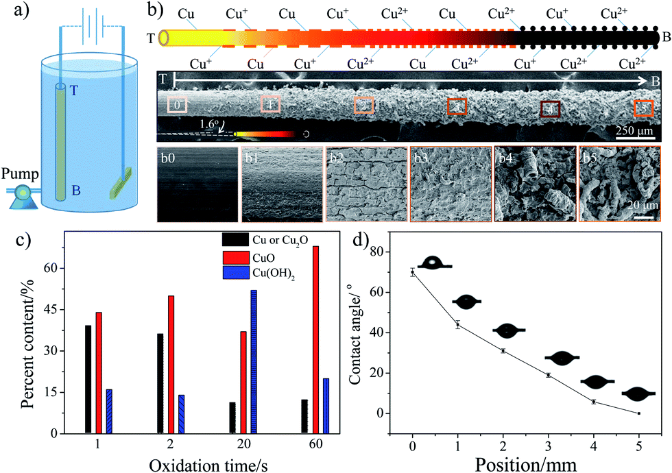 | ||
| Fig. 1 Schematic of the formation of wettable gradient and Laplace pressure gradient on a copper wire and the change in the microstructure, chemical composition, and water contact angle on Sample-A surface. (a) Apparatus for gradient anodic oxidation. (b) Schematic of the change in microstructure, chemical composition and SEM images of the copper wire surface (Sample-A). SEM images show that crisp and porous structures gradually appear after applying the gradient anodic oxidation process and the obvious directional roughness gradient is formed. In addition, the change in the diameter of the wire is also observed and a conical structure is formed (T: top area and B: bottom area of the copper wire during gradient anodic oxidation). (c) Chemical composition of copper wire prepared at different anodic oxidation time. The chemical composition gradient is also formed during the gradient anodic oxidation process. (d) Contact angles of Sample-A at different areas (the zero position is defined as the boundary between unoxidized part and oxidized part). | ||
The chemical properties of the copper wire were analysed using X-ray photoelectron spectroscopy (XPS). Fig. S1a† represents the XPS spectrum of Cu (2p) for copper wires after different oxidation times. The presence of shake-up satellite peaks confirms the formation of Cu2+ on the surface, i.e., cupric oxide (CuO) or cupric hydroxide (Cu(OH)2).14,15 By investigating the binding energy for each core level, one can identify the detailed surface chemical composition.16 Because Cu 2p3/2 and Cu 2p1/2 play similar roles in determining the Cu valence, here only Cu 2p3/2 is discussed (Fig. S1b, ESI†). According to the literature,15 the Cu 2p3/2 core level spectrum shows a main peak envelope curve-fitted into three components centered at 932.5, 933.8 and 935.1 eV. The peak at 932.5 eV is attributed to either metallic Cu or Cu2O. The component at 933.8 and 935.1 eV arises because of the presence of CuO and Cu(OH)2. The XPS results indicate that with the increase in the oxidation time, the metallic copper or Cu2O content decrease obviously, but the CuO and Cu(OH)2 content increases sharply (Fig. 1c). In other words, the Cu or Cu2O is oxidized to form Cu2+. We also use Energy Dispersive Spectrometry (EDS) to investigate the elements in the copper wire. The EDS analysis results (Table S1†) show that two main elements, copper and oxygen, exist on the copper wire surface. With the increase in the oxidation time, the atomic ratio (O/Cu) increases from 0.13 to 2.35, which is consistent with the XPS results. Therefore, the XPS and EDS results suggest that chemical valence Cu+ coexists with valence Cu2+. With the increase in the oxidation time, more and more Cu or Cu+ are oxidized to form Cu2+. Obviously, a chemical composition gradient is also induced on the copper wire during gradient anodic oxidation treatment.
Fig. 1d shows the contact angle (CA) of Sample-A on different areas, which indicates the CA changes gradually from 70° to 0° along the direction from T to B, showing an average wettable gradient of 14° mm−1 (average wettable gradient: ratio of CA change to the length of wettable gradient). The CA is expected to depend upon the chemical composition and surface morphology. As the distance from the top to the bottom increases, the surface becomes rough gradually (multi-scale structure is formed) and more and more Cu or Cu+ are oxidized to form more hydrophilic CuO and Cu(OH)2.17 At the bottom part, the surface has a more hydrophilic chemical composition and a rougher structure, resulting in a CA of 0°. Clearly, the formation of a great wettable gradient is mainly ascribed to the cooperation between the chemical composition and the surface morphology (Wenzel's theory18). To obtain the different wettable gradients, we adjusted the volume flow velocity of the electrolyte to control the oxidation time gradient. The results indicate that the average wettable gradient could be controlled from 35° mm−1 to 4° mm−1 via the volume flow velocity of the electrolyte (from 5.3 L h−1 to 42.2 L h−1) and the corresponding length of the wettable gradient changes from 2 to 18 mm (see Fig. S2 and S3, ESI†), whereas, the apex angle of the copper wire is always about 1.6° at different oxidation treatment conditions. Obviously, via the gradient anodic oxidation method, not only a wettable gradient but a Laplace pressure gradient is also induced effectively on the surface of the copper wire and the value of the wettable gradient can be adjusted easily.
The movement behaviours of the droplet on the multi-gradient surface are observed via a charge coupled device (CCD) camera (Fig. 2a–c). When a water droplet is dripped on the copper wire with a wettable gradient of more than 4.5° mm−1 (the droplet is dripped on the boundary between the unoxidized part and the oxidized part), it would be driven towards the more hydrophilic area for some distance and then pinned on the copper wire. For different volumes of the droplet, with the increase in the wettable gradient, the movement distance always increases first and then decreases, showing a peak at 14° mm−1 (Fig. 2d). In addition, an interesting phenomenon is observed that for a given sample, there seems to be a balance position and the droplet usually moves to the balance position no matter where this droplet is placed (within balance position) (Fig. 3a), i.e., X + L = constant (X is the initial position and L is the movement distance of the droplet. The zero position (X = 0) is defined as the boundary between the unoxidized part and the oxidized part). For surfaces with different wettable gradients, the balance position is different (Fig. 3b). For example, for the surface with 14° mm−1, the balance position is 4.5 mm (Fig. 3a). For 5° mm−1, 7° mm−1, 10° mm−1, 23° mm−1, the position changes to 0.8 mm, 1.4 mm, 2.5 mm, 3.2 mm, respectively (Fig. 3b). However, when a droplet is dripped beyond the balance position, the droplet is always pinned on the wire and no movement is observed. In addition, the copper wire with a wettable gradient could not only drive the water droplet, but also make the oil droplet move on it, and the same behaviour is observed (Fig. S4, ESI†).
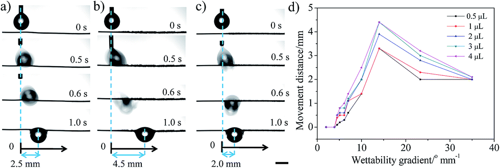 | ||
| Fig. 2 Water droplet movement behaviour on the copper wire with a disparate wettable gradient (the droplet is dripped on the boundary between the unoxidized part and the oxidized part, X = 0): (a) 10° mm−1, (b) 14° mm−1, (c) 35° mm−1. Optical images show that the water droplet is driven fast towards the more hydrophilic area and shows a different distance with a disparate wettable gradient. The scale is 2 mm. (d) The movement distance of the droplet on the copper wire with different wettable gradients. For different volumes of droplet, the movement distance always increases first and then decreases, showing a peak at 14° mm−1. | ||
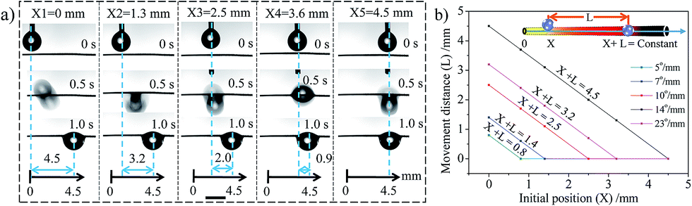 | ||
| Fig. 3 (a) The droplet movement behaviour on copper wire with a wettable gradient of 14° mm−1 when the droplet is placed at different initial positions (within balance position). (b) The relationship between the initial position (X) and the movement distance (L) for surfaces with different wettable gradients. There seems to be a balance position and the droplet usually moves to the balance position no matter where the droplet is placed, i.e., X + L = constant (X is the initial position and L is the movement distance of the droplet. The zero position (X = 0) is defined as the boundary between the unoxidized part and the oxidized part). The volume of the droplet is 4 μL. The scales are 2 mm. | ||
In order to understand this unique phenomenon thoroughly, we analysed the forces exerted on the droplets. It is considered that there are three forces that influence the motion of droplets: wettability gradient force (FW), Laplace pressure gradient (FL) and hysteresis force (FH), which can be related to a surface wettability gradient, conical shape of wire and CA hysteresis, respectively. The wettable gradient force induced by diverse CAs on the two sides of the droplet would drive droplets towards the more wettable region of the surface, which could be described as:12
FW = πR2γk![[thin space (1/6-em)]](https://www.rsc.org/images/entities/char_2009.gif) sinθ = FW(R,k,θ) sinθ = FW(R,k,θ)
| (1) |
| FL = Aα + B | (2) |
|
FH = 2Rγ(cosθr − cosθa)
| (3) |
|
FT = FW + FL − FH = Rγ(πRksinθ − 2(cosθr − cosθa)) + FL = FT(k,x)
| (4) |
Therefore, for a given volume of droplet, FT is regarded as a function of the average wettable gradient (k) and the position of droplet (x) (θ, θr and θa are only function of position (x) and FL is a constant). When the value of k is small, the wettable gradient force is small (FT is below zero) and no movement of the droplet is observed. The increase in the value of k would induce an increase an FT (eqn (4)). When the value of k is above some critical value (4.5° mm−1, Fig. 2), the sum of FW and FL surpasses FH (FT > 0) and the droplet would be driven to the more wettable side. As the droplet moves to a more wettable area (θ decreases), the value of FW decreases (eqn (1)) and the value of FH increases gradually (the difference between the θr and θa increases, Fig. S5, ESI†), which would lead to a decrease in FT. When FT = 0, the motion would be halted. Although the increase in k could induce a larger FT, the increase also shortens the length of the wettable gradient gradually, which would limit the driving distance (Fig. S3, ESI†). Thus, the driving distance shows a peak at 14° mm−1 (the surface has larger FT and length of wettable gradient). It seems that when k < 14° mm−1, the movement distance is mainly controlled by the wettable gradient and the Laplace pressure gradient. When k > 14° mm−1, the movement distance is mainly controlled by the length of the wettable gradient. For example, for 23° mm−1, the movement distance (3.2 mm) is very close to the length of the wettable gradient (3.1 mm, Fig. S3†), consistent with the speculation above. For a given surface (k is a constant), FT could be regarded as a function of position (x), i.e., FT(x). Accordingly, the droplets would always stop and be balanced at the same position (FT(x) = 0) no matter where the droplets were released (within the balance position), i.e., X + L = constant, which corresponds well with our experimental results (Fig. 3b). Obviously, the result implies that the movement behaviors of the droplet could be predicted and controlled by the initial position and/or the magnitude of the wettable gradient (according to Fig. 3b).
More importantly, the introduction of surface wettability and the Laplace pressure gradient also helps the directional transformation of the water drop during the fog-water collection process, which in turn speeds up the drop coalescence and improves the water collection efficiency. The comparison of the fog-water collection behaviour between the original copper wire and Sample-A is shown in Fig. 4a and b. The results indicate that on the original copper wire, the droplets simply grow up at the initial position during the collection process. As for Sample-A, the droplets move towards to the more hydrophilic area and gradually coalesce into a bigger one during the collection process. Compared to the recent research with a transportation distance of 5 mm,13 the water droplet could achieve a much longer transportation length of ∼1 cm in our study, which means that the transportation distance is further increased nearly 1 time. Ju et al.20 got a one period collection process on CCW with a gradient wettability in 56.9 s with a fog flow velocity of about 20–30 cm s−1 at room temperature, while the transport distance was only 823 μm. Heng et al.21 developed a branched ZnO wire structure for water collection, and collected 6 μL of water within 30 min. Xu et al.22 designed a water collecting array of PCCWs, and when they put this array at a room temperature of 15 °C, 90% relative humidity, and a fog impacting velocity of 2.4 m s−1 with an impact angle of 90°, the highest water collection rate can reach 0.618 g cm−2 h−1. Different researchers investigated their samples in different systems, which makes it difficult to compare the results with our results absolutely. Therefore, we compared Sample-A to the original copper wire in the same system. Fig. 4c shows a comparison of the water hanging ability and water collection efficiency between the original copper wire and Sample-A. The maximal water-hanging volume of Sample-A exceeds by 12.84 μL, i.e., increases by 25%, which may account for the roughness of the structures. Meanwhile, the time for one period collection process before the hanging droplet detaches from the wire shortens (64 s, decreases by 30%) and the water collection efficiency increases by 78%. Obviously, after imposing a gradient anodic oxidation process, the gradient copper wire displays a more efficient water collection and a larger hanging ability, which is mainly due to the fact that the additional driving forces from the wettable gradient and Laplace pressure gradient could induce directional movement of tiny water drops to reveal the original collection points for a new cycle of collection.19,23–26
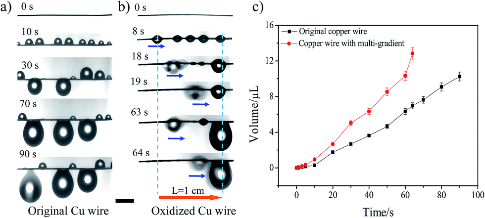 | ||
| Fig. 4 Comparison of fog-water collection behavior between original copper wire and multi-gradient copper wire. (a) Water collection process of original copper wire. (b) Water movement behavior on the surface of Sample-A. The results indicate that the droplets simply grow at the initial position during the collection process on the original copper wire. But for Sample-A, the droplets move towards to the more hydrophilic area gradually and coalesce into a bigger one during the collection process. The water transportation length (L) reaches 1 cm. The scales are 2 mm. (c) Comparison of water collection abilities between original copper wire and Sample-A. Obviously, the copper wire with a multi-gradient displays a more efficient water collection and a larger hanging ability. | ||
Conclusions
In conclusion, in order to achieve longer transportation of a water droplet on a wire, we applied the gradient anodic oxidation method to fabricate a wettable gradient and Laplace pressure gradient simultaneously on a copper wire. By the cooperation of the wettable gradient and the Laplace pressure gradient, we realized the controlled movement of a droplet on a wire. The movement distance of a droplet can be adjusted between 0 and 4.5 mm for target transportation via the initial position and/or the magnitude of the wettable gradient. More interesting, the copper wire with a multi-gradient displays more efficient water collection and a larger hanging ability. This study is helpful in designing smart materials for developing applications in microfluidic devices and fog-water collection.25,26Acknowledgements
This work was supported by the National Key Basic Research Program of China (2013CB933000), the National Natural Science Foundation of China (21673015), and Fundamental Research Funds for Central Universities (YWF-15-HHXY-017, YWF-16-JCTD-A-01) and Aeronautical Science Foundation of China (2015ZF51060).Notes and references
- Y. H. Liu, M. Andrew, J. Li, M. J. Yeomans and Z. K. Wang, Nat. Commun., 2015, 6, 10034 CrossRef CAS PubMed.
- F. Schellenberger, N. Encinas, D. Vollmer and H. J. Butt, Phys. Rev. Lett., 2016, 116, 096101 CrossRef PubMed.
- K. H. Chu, R. Xiao and E. N. Wang, Nat. Mater., 2010, 9, 413 CrossRef CAS PubMed.
- E. Ueda and P. A. Levkin, Adv. Mater., 2013, 25, 1234 CrossRef CAS PubMed.
- C. Duprat, S. Protiere, A. Y. Beebe and H. A. Stone, Nature, 2012, 482, 510 CrossRef CAS PubMed.
- M. J. Hancock, K. Sekeroglu and M. C. Demirel, Adv. Funct. Mater., 2012, 22, 2223 CrossRef CAS PubMed.
- J. Bico, B. Roman, L. Moulin and A. Boudaoud, Nature, 2004, 432, 690 CrossRef CAS PubMed.
- Q. B. Wang, X. Yao, H. Liu, D. Quéré and L. Jiang, Proc. Natl. Acad. Sci. U. S. A., 2015, 112, 9247 CrossRef CAS PubMed.
- E. Lorenceau and D. Quere, J. Fluid Mech., 2004, 510, 29 CrossRef.
- C. J. Lv, C. Chen, Y. C. Chuang, F. G. Tseng, Y. J. Yin, F. Grey and Q. S. Zheng, Phys. Rev. Lett., 2014, 113, 026101 CrossRef PubMed.
- C. Schlaich, C. L. Cuellar, L. Yu, K. Achazi, Q. Wei and R. Haag, ACS Appl. Mater. Interfaces, 2016, 8, 29117 CAS.
- S. L. Feng, S. J. Wang, L. C. Gao, G. J. Li, Y. P. Hou and Y. M. Zheng, Angew. Chem., Int. Ed., 2014, 53, 6163 CrossRef CAS PubMed.
- Y. Chen, L. Wang, Y. Xue, L. Jiang and Y. M. Zheng, Sci. Rep., 2013, 3, 2927 CrossRef PubMed.
- K. Manabe, T. Matsubayashi, M. Tenjimbayashi, T. Moriya, Y. Tsuge, K. H. Kyung and S. Shiratori, ACS Nano, 2016, 10, 9387 CrossRef CAS PubMed.
- F. Xiao, S. J. Yuan, B. Liang, G. Q. Li, S. O. Pehkonen and T. J. Zhang, J. Mater. Chem. A, 2015, 3, 4374 CAS.
- M. M. Sung, K. Sung, C. G. Kim, S. S. Lee and Y. Kim, J. Phys. Chem. B, 2000, 104, 2273 CrossRef CAS.
- X. F. Wu, H. Bai, J. X. Zhang, F. E. Chen and G. Q. Shi, J. Phys. Chem. B, 2005, 109, 22836 CrossRef CAS PubMed.
- R. N. Wenzel, J. Phys. Colloid Chem., 1948, 53, 1466 CrossRef.
- A. Ghosh, R. Ganguly, T. M. Schutzius and C. M. Megaridis, Lab Chip, 2014, 14, 1538 RSC.
- J. Ju, K. Xiao, X. Yao, B. Hao and L. Jiang, Adv. Mater., 2013, 25, 5937 CrossRef CAS PubMed.
- X. Heng, M. M. Xiang, Z. H. Lu and C. Luo, ACS Appl. Mater. Interfaces, 2014, 6, 8032 CAS.
- T. Xu, Y. C. Lin, M. X. Zhang, W. W. Shi and Y. M. Zheng, ACS Nano, 2016, 10, 10681 CrossRef CAS PubMed.
- P. Lovass, M. Branicki, R. Toth, A. Braun, K. Suzuno, D. Ueyama and I. Lagzi, RSC Adv., 2015, 5, 48563 RSC.
- C. S. Sharma, J. Combe, M. Giger, T. Emmerich and D. Poulikakos, ACS Nano, 2017, 11, 1673 CrossRef CAS PubMed.
- R. L. Agapov, J. B. Boreyko, D. P. Briggs, B. R. Srijanto, S. T. Retterer, C. P. Collier and N. V. Lavrik, ACS Nano, 2013, 8, 860 CrossRef PubMed.
- K. Manabe, T. Matsubayashi, M. Tenjimbayashi, T. Moriya, Y. Tsuge, K. H. Kyung and S. Shiratori, ACS Nano, 2016, 10, 9387 Search PubMed.
Footnotes |
| † Electronic supplementary information (ESI) available: Fig. S1–S5, Table S1. Experimental apparatus, XPS results, oil droplet movement, the change of ACA, CA and RCA on Sample-A. See DOI: 10.1039/c7ra05534j |
| ‡ These authors contributed equally to this study and share first authorship. |
| This journal is © The Royal Society of Chemistry 2017 |