 Open Access Article
Creative Commons Attribution 3.0 Unported Licence
Hierarchically structured carbon nanotube–polyaniline nanobrushes for corrosion protection over a wide pH range†
Guodong Qiua,
Aiping Zhu*a and
Chaoqun Zhang *b
*b
aSchool of Chemistry and Chemical Engineering, Yangzhou University, Yangzhou 225002, China. E-mail: apzhu@yzu.edu.cn; Tel: +86 0514 87993691
bCollege of Materials and Energy, South China Agricultural University, Guangzhou 510642, China. E-mail: nwpuzcq@gmail.com
First published on 14th July 2017
Abstract
Carbon nanotube–polyaniline brush-like nanostructures have been successfully synthesized through in situ oxidative polymerization of aniline on the surface of carboxylated multi-walled carbon nanotubes. The diameter of the resultant tubular nanobrushes is dependent on the mass ratio of c-MWNTs to aniline. The as-designed carbon nanotube–polyaniline nanobrushes exhibit superior electroactivity not only in acidic, but also in neutral and alkaline environments. The excellent anticorrosion performance has been achieved by incorporation of these nanobrushes into amine cured epoxy modified acrylic resin. It is found that the good barrier property of the nanobrush coating against neutral and alkaline corrosion media penetration and its predominant passivation protection against acidic medium offer anticorrosion protection for steel over a wide pH range. The novel carbon nanotube–polyaniline nanobrushes prepared using this facile route extend the application of polyaniline to a wider range of pH environments and facilitate a more environmentally friendly and economical system than traditional heavy metal coatings and their oxide coatings, in the application of anticorrosion protection of metals.
1. Introduction
Among the conducting polymers, polyaniline (PANI) has been found to be one of the most promising materials for wide applications in rechargeable batteries1,2 electrocatalysis,3 electrochromic devices,4 conversion of light to electricity and corrosion resistance5,6 due to its tunable conductivity, good environmental stability, nontoxic property and low cost.7–9 Since Deberry first reported the protective effect of PANI on steels for long periods in sulfuric acid solution,10 the PANI based coatings have been considered in applications for the anticorrosion protection of aluminum, iron, copper and other metals, as a replacement for traditional heavy metal coatings and their oxide coatings.11–13Several mechanisms underlying the protective behavior of PANI coatings have been proposed and reported, such as physical barrier protection, passivation protection, corrosion inhibition, electric field effect, etc.14,15 The passivation protection of steel by PANI has been reported to be the most efficient in which a thin oxide protective layer is formed as a result of electrochemical interaction between the polymer and metal surface. Wessling et al. reported that the passive iron oxide layer was formed between PANI coatings and the metal surface after immersed in 3 wt% NaCl solution, resulting in decrease of the corrosion current and increase of the corrosion potential revealed by Tafel polarization curve test.16 Talo et al. found that the metal surface with PANI containing epoxy coating presented gray color after immersed in 0.6 M NaCl solution for a period of time. X-ray photoelectron spectroscopy (XPS) revealed that these color change are results of the formation of iron oxides.17 Chen et al. studied the anticorrosion property of epoxy coating filled with PANI and found an obvious increase on the resistance of the coating in neutral solution during 30 day of immersion, which indicated the formation of a passivation layer between the metal surface and coating.18 However, the occurrence of deprotonation of PANI when pH >4 greatly reduces its conductivity and electroactivity,19,20 leading to the loss of passivation protection of PANI in basic solution. Thus, the practical application of PANI as anticorrosion coatings is limited, especially in the application of marine corrosion protection with high pH values (pH ≥ 7).
The use of aniline derivatives and polymer blends with acid doping mechanism is an efficient and economical way to reduce the pH dependence of redox activity of PANI. For example, Mu et al. investigated the copolymerization of 5-aminosalicylic acid and p-aminophenol with aniline by introducing pH functional groups of –COOH and –OH into PANI polymer backbone to maintain a good electroactivity in a wide pH range.21 Advincula et al. showed that the electroactivity of PANI can be shifted to neutral electrolytes by doping PANI with macromolecular acids such as poly(acrylic acid) poly(vinyl sulfonate) and poly(styrene sulfonate), in which strong interactions existed between poly(anions) with polyaniline chains.22,23 However, the electroactivity of all these PANI complexes still decayed to certain degree with increasing pH from acid to alkaline environments. The incorporation of conductive nano-fillers into polymer matrix based on charge transfer doping mechanism is another promising way to solve this problem due to their synergistic and complementary behaviors. The conductive carbon-based nanomaterials such as carbon nanotubes (CNTs)24,25 as the dopant would be preferred due to its large specific surface area, remarkable performance in terms of mechanical, electrical, and thermal properties. Liu et al. used LBL self-assembly method to prepare PANI/CNTs multilayer films by alternating immersion of Au substrate into the solutions of polyaniline (PANI) and poly(aminobenzenesulfonic acid)-modified single-walled carbon nanotubes and the multilayer film has stable electrochemical activity in neutral solution.24 Zhou et al. prepared PANI/CNTs nanocomposite by simply mixture of polyaniline emeraldine base (PANI) with pristine single-walled carbon nanotubes and found that the effective doping of CNTs on PANI can maintain its electroactivity with a fast electron transfer property and a high stability in the neutral and alkaline medium.25
In this work, hierarchically structured carbon nanotube–polyaniline nano-brushes (c–PANI) were prepared by in situ polymerization with carboxylated carbon nanotubes (c-MWNTs) as charge transfer doping agents. The effects of mass ratio of c-MWNTs to aniline on the morphologies and structures of the final composites were investigated. Transmission electron microscopy (TEM), Fourier transform infrared spectroscopy (FTIR), Ultraviolet-visible spectroscopy (UV-vis), and X-ray Powder Diffraction (XRD) were used to characterize the carbon nanotube–polyaniline composites. The cyclic voltammetry (CV) measurements showed that the construction of the unique nanobrush structure leads to the formation of new charge transfer doping through π–π stacking interactions and hydrogen bonding between carbon nanotubes and polyaniline, resulting in superior electroactivity not only in acidic, but also in neutral and alkaline environments. Furthermore, the mechanism by which these nanobrush-containing amine cured epoxy modified acrylic resins coatings afford corrosion protection towards carbon steel has been investigated and discussed.
2. Experimental
2.1 Materials
Carboxylated multi-walled carbon nanotubes (purity 95%, diameter 10–20 nm, length 10–30 μm) were purchased from Beijing DK nano technology Co. Ltd. Aniline, ammonium persulfate (APS), sulfuric acid and ethanol were purchased from Sinopharm Chemical Reagent Co. Ltd. Dodecyl diphenyl ether sodium sulfonate used as the anionic surfactant (2A1) was provided by DOW Co. Ltd. Epoxy modified acrylic resin, amino resin curing agent and organic phosphoric acid catalyst from Sanmu Group Co. Ltd. were used to prepare waterborne coatings.2.2 Preparation of c–PANI nanobrushes
The c–PANI nanobrushes were prepared via oxidative polymerization of aniline on the surface of c-MWNTs. Briefly, 0.116, 0.233, 0.466 and 0.931 g of c-MWCNT were respectively dispersed in 80 mL distilled water, followed by the addition of 0.01 mol aniline monomer and 9.3 mg of 2A1 as dispersant. The mixture was further dispersed with the combination of stirring and ultrasonication for 1 h. Subsequently, an appropriate amount of concentrated sulfuric acid was used to adjust the pH of the solution to 1. Then, 20 mL of 0.05 mol L−1 H2SO4 aqueous solution containing 0.01 mol APS was added dropwise into the as-prepared suspension in an ice bath. The reaction was allowed with a moderate stirring at a reaction temperature of 0–5 °C for 6 h. Finally, c–PANI nanobrushes were obtained by washing with ethanol, water and 0.05 mol L−1 H2SO4 aqueous solution and drying in vacuum at 80 °C for 24 h.2.3 Preparation of PANI and c–PANI containing epoxy modified acrylic resin coatings
PANI or c–PANI nanobrushes were dispersed into epoxy modified acrylic resin followed by the uniformly addition of the amino resin curing agent and organic phosphoric acid catalyst. A dipping method was used followed by curing at 130 °C for 0.5 h to form coating with about 30 μm of thickness on steel bars for anticorrosion analysis.2.4 Characterization
The morphologies of PANI and the c–PANI composites were analyzed by transmission electron microscopy (TEM; Philips Tecnai12, 200 kV). X-ray diffraction (XRD) data were collected from 10° to 80° (2θ angle) from a Bruker AXS D8 ADVANCE X-ray diffractometer using Cu Kα radiation (40 kV, 40 mA). Fourier transform infrared (FTIR) spectroscopy was performed on a Bruker VECTOR 22 spectrometer using KBr sample pellets. The UV-vis spectra of 0.01 g sample in 10 mL of N-methyl-2-pyrrolidone (NMP) were obtained using a PERSEE TU-1901 spectrophotometer. Optical micrographs of waterborne coatings were taken by a MA-2001 optical microscope. CV tests were performed on a CHI660a electrochemical station using a three-electrode configuration in Swagelok cells. The electrolytes was 3.5% NaCl. The working electrodes were prepared by drop-casting the composite suspension (1 wt%, in methanol) on glassy carbon steel stick. The counter and reference electrodes were a platinum foil and a Ag/AgCl electrode, respectively. Electrochemical impedance spectroscopy (EIS) measurements were performed with an EcoChemie AutoLab 302N analyzer. A three-electrode cell was also used employing the coated steel as a working electrode with an exposed area of 4.7 cm2, a platinum foil and a saturated Hg/Hg2Cl2 electrode as counter and reference electrodes, respectively. XPS measurements were conducted on an ESCALAB 250Xi spectrometer with an Al Kα X-ray source (1486.5 eV). For the sample of XPS analysis, the soaked coating was carefully striped away and to expose the underlying steel surfaces.3. Results and discussion
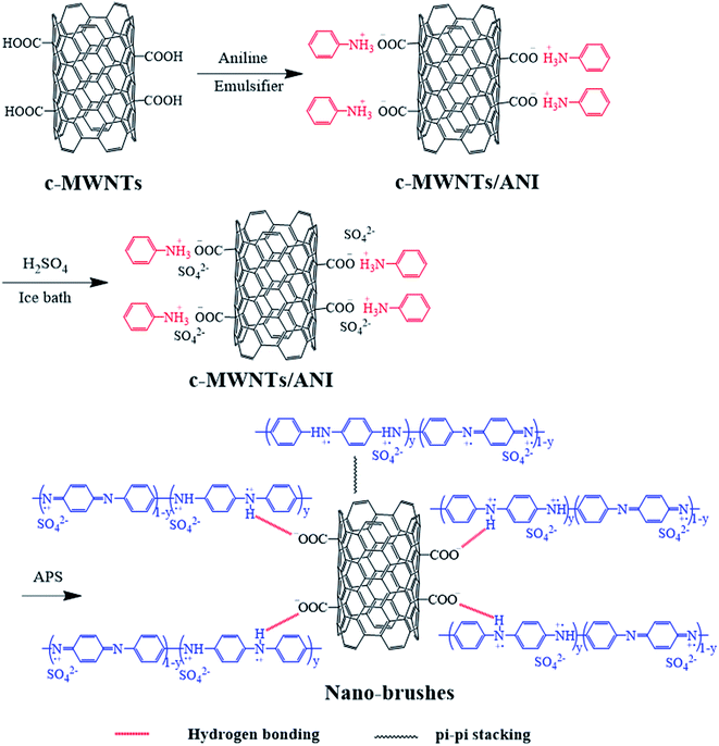
Carbon nanotube–polyaniline brush-like nanostructures have been synthesized through in situ oxidative polymerization of aniline on the surface of carboxylated multi-walled carbon nanotubes as shown in Fig. 1. The interactions between PANI and nanotubes take place as a consequence of the oxidation polymerization, including π–π stacking between quinoid ring of PANI and the π-bonded surface of nanotubes, hydrogen bonding between –OH groups on the surface of nanotubes and –NH of PANI, and electrostatic interaction between –COO− groups of nanotubes and –NH+ of PANI. The morphology and chemical structures of the resulting carbon nanotube bushes were characterized by TEM, FTIR, UV-vis, and XRD, respectively.Fig. 2 shows the TEM images of c–PANI nanobrushes. The image of pristine PANI is also presented for comparison. Fig. 2a shows clearly that PANI exhibits a short-fiber morphology with serious agglomerate. It is also show that (Fig. 2b–e) a tubular layer of PANI is uniformly coated on the surface of c-MWCNT through oxidative polymerization. These composites demonstrate homogeneous nanobrush structures in which c-MWCNT serves as the conductive core and PANI as the hair brushes. The diameter of these tubular c–PANI is dependent on the mass ratio of c-MWNTs to aniline (Wr). As Wr increases from 1![[thin space (1/6-em)]](https://www.rsc.org/images/entities/char_2009.gif) :
:![[thin space (1/6-em)]](https://www.rsc.org/images/entities/char_2009.gif) 8 to 1
8 to 1![[thin space (1/6-em)]](https://www.rsc.org/images/entities/char_2009.gif) :
:![[thin space (1/6-em)]](https://www.rsc.org/images/entities/char_2009.gif) 4, the diameters of the composites decreases from 50 nm (Fig. 2b) to 20 nm (Fig. 2c). When Wr continue to increase to 1
4, the diameters of the composites decreases from 50 nm (Fig. 2b) to 20 nm (Fig. 2c). When Wr continue to increase to 1![[thin space (1/6-em)]](https://www.rsc.org/images/entities/char_2009.gif) :
:![[thin space (1/6-em)]](https://www.rsc.org/images/entities/char_2009.gif) 2 and 1
2 and 1![[thin space (1/6-em)]](https://www.rsc.org/images/entities/char_2009.gif) :
:![[thin space (1/6-em)]](https://www.rsc.org/images/entities/char_2009.gif) 1, the diameters of the composites decreases sharply but still larger than that of pure c-MWNTs. After the formation of c–PANI composites, these c-MWNTs are found to be entrapped in PANI chains leading to increase of the c–PANI size. Obviously, the PANI chains are dispersed and glued into surface of c-MWNTs, not simply mixed up or blended with c-MWNTs, resulting in less agglomerate behavior of PANI without any surfactant.26
1, the diameters of the composites decreases sharply but still larger than that of pure c-MWNTs. After the formation of c–PANI composites, these c-MWNTs are found to be entrapped in PANI chains leading to increase of the c–PANI size. Obviously, the PANI chains are dispersed and glued into surface of c-MWNTs, not simply mixed up or blended with c-MWNTs, resulting in less agglomerate behavior of PANI without any surfactant.26
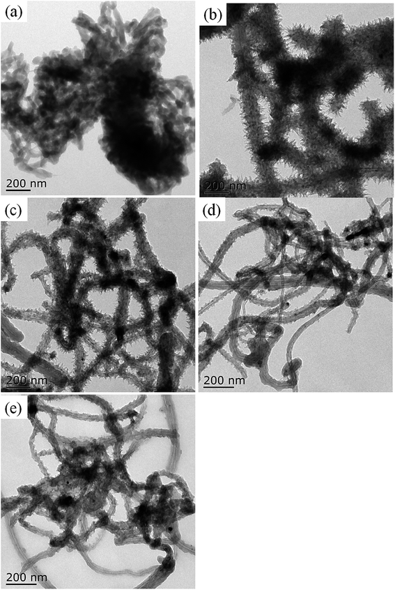 | ||
Fig. 2 TEM images of PANI (a) and c–PANI nanobrushes prepared with the Wr of (b) 1![[thin space (1/6-em)]](https://www.rsc.org/images/entities/char_2009.gif) : :![[thin space (1/6-em)]](https://www.rsc.org/images/entities/char_2009.gif) 8; (c) 1 8; (c) 1![[thin space (1/6-em)]](https://www.rsc.org/images/entities/char_2009.gif) : :![[thin space (1/6-em)]](https://www.rsc.org/images/entities/char_2009.gif) 4; (d) 1 4; (d) 1![[thin space (1/6-em)]](https://www.rsc.org/images/entities/char_2009.gif) : :![[thin space (1/6-em)]](https://www.rsc.org/images/entities/char_2009.gif) 2 and (e) 1 2 and (e) 1![[thin space (1/6-em)]](https://www.rsc.org/images/entities/char_2009.gif) : :![[thin space (1/6-em)]](https://www.rsc.org/images/entities/char_2009.gif) 1. 1. | ||
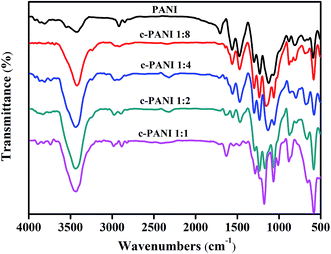
Fig. 3 showed the FTIR spectra of PANI and c–PANI nanobrushes. The FTIR spectrum of PANI display the typical vibration modes with bands at 3423 cm−1 (N–H stretching), 1562 cm−1 (C![[double bond, length as m-dash]](https://www.rsc.org/images/entities/char_e001.gif) C stretching, quinoid rings), 1476 cm−1 (C
C stretching, quinoid rings), 1476 cm−1 (C![[double bond, length as m-dash]](https://www.rsc.org/images/entities/char_e001.gif) C stretching, benzenoid rings), 1299 cm−1 (C–N stretching, quinoid rings), 1231 cm−1 (C–N stretching, benzenoid rings).27 With increasing content of c-MWNTs, the peaks at 1562 cm−1 and 1299 cm−1 gradually shift to lower wave numbers (1543 cm−1, 1286 cm−1). In addition, a notable increase in the intensity ratio of the quinoid to benzenoid ring is observed for c–PANI nanobrushes. The quinoid peak is a measurement of the degree of delocalization of the electrons and, thus, it is a characteristic peak of electrical transport.28 This suggests that interactions between PANI and nanotubes take place as a consequence of the oxidation polymerization as shown in Fig. 3, including π–π stacking between quinoid ring of PANI and the π-bonded surface of nanotubes, hydrogen bonding between –OH groups on the surface of nanotubes and –NH of PANI, and electrostatic interaction between –COO− groups of nanotubes and –NH+ of PANI.29 Furthermore, these interactions facilitate charge-transfer processes between the PANI and nanotubes, and thereby influence the transport properties of the composites.
C stretching, benzenoid rings), 1299 cm−1 (C–N stretching, quinoid rings), 1231 cm−1 (C–N stretching, benzenoid rings).27 With increasing content of c-MWNTs, the peaks at 1562 cm−1 and 1299 cm−1 gradually shift to lower wave numbers (1543 cm−1, 1286 cm−1). In addition, a notable increase in the intensity ratio of the quinoid to benzenoid ring is observed for c–PANI nanobrushes. The quinoid peak is a measurement of the degree of delocalization of the electrons and, thus, it is a characteristic peak of electrical transport.28 This suggests that interactions between PANI and nanotubes take place as a consequence of the oxidation polymerization as shown in Fig. 3, including π–π stacking between quinoid ring of PANI and the π-bonded surface of nanotubes, hydrogen bonding between –OH groups on the surface of nanotubes and –NH of PANI, and electrostatic interaction between –COO− groups of nanotubes and –NH+ of PANI.29 Furthermore, these interactions facilitate charge-transfer processes between the PANI and nanotubes, and thereby influence the transport properties of the composites.
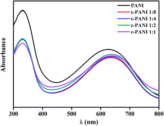
The dominant features between the PANI and nanotubes is also confirmed by the UV-vis spectra of PANI and c–PANI composites (Fig. 4). The absorption peak corresponding to the transition of the exciton of the quinone shifted from 627 nm to 639 nm after the formation of composites. A similar red-shifted was also reported on PANI/graphene systems, which is ascribed by the interactions between c-MWNTs and quinoid ring in PANI.30
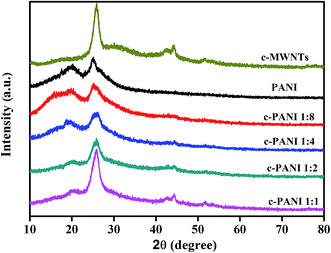
The powder XRD patterns of c-MWNTs, PANI and c–PANI composites are shown in Fig. 5. The diffraction peaks of c-MWNTs appear at 2θ = 25.8° and 44.2° representing the crystal planes of (002) and (100) of graphite.31 The crystalline peaks of pristine PANI appear at 2θ = 15.9°, 19.9° and 24.9°, corresponding to (011), (020) and (200) crystal planes in its emeraldine salt state, respectively.32 The patterns of c–PANI composites possess all characteristic diffraction peaks of c-MWNTs and PANI. The intensity of conspicuous peak at 2θ = 19.9°, corresponding to the periodicity of the crystallographic planes that are perpendicular to the doped PANI chains,33 decreases obviously when the Wr increases from 1![[thin space (1/6-em)]](https://www.rsc.org/images/entities/char_2009.gif) :
:![[thin space (1/6-em)]](https://www.rsc.org/images/entities/char_2009.gif) 4 to 1
4 to 1![[thin space (1/6-em)]](https://www.rsc.org/images/entities/char_2009.gif) :
:![[thin space (1/6-em)]](https://www.rsc.org/images/entities/char_2009.gif) 1. And the intensity of peak at 2θ = 44.2° increases with increasing Wr from 1
1. And the intensity of peak at 2θ = 44.2° increases with increasing Wr from 1![[thin space (1/6-em)]](https://www.rsc.org/images/entities/char_2009.gif) :
:![[thin space (1/6-em)]](https://www.rsc.org/images/entities/char_2009.gif) 4 to 1
4 to 1![[thin space (1/6-em)]](https://www.rsc.org/images/entities/char_2009.gif) :
:![[thin space (1/6-em)]](https://www.rsc.org/images/entities/char_2009.gif) 1. This result indicates that c-MWNTs as a charge transfer dopant for PANI compete with sulfuric acid dopant, and influence the crystallinity of PANI through the π–π stacking and hydrogen bonding interactions between c-MWNTs and PANI.
1. This result indicates that c-MWNTs as a charge transfer dopant for PANI compete with sulfuric acid dopant, and influence the crystallinity of PANI through the π–π stacking and hydrogen bonding interactions between c-MWNTs and PANI.
To further elucidate the charge transfer effect of c-MWNTs on the electroactivity of PANI, the electrochemical activities of PANI and c–PANI composites were studied by CV measurements in 3.5 wt% NaCl with pH of 1, 7 and 9 at 25 °C, respectively. As shown in Fig. 6, each curve exhibits a similar shape with two pairs of redox at pH of 1. The redox peaks for PANI locate at around 0.10/0.22 V and 0.61/0.68 V as shown in Fig. 6a, which could be attributed to the redox transitions between leucoemeraldine and emeraldine, and the faradaic transformation of emeraldine to pernigraniline,34 respectively. In the case of c–PANI composites, the cathodic redox peaks shift negatively while the anodic redox peaks shifted positively with the increase content of c-MWNTs. The c–PANI composites with Wr of 1![[thin space (1/6-em)]](https://www.rsc.org/images/entities/char_2009.gif) :
:![[thin space (1/6-em)]](https://www.rsc.org/images/entities/char_2009.gif) 8, 1
8, 1![[thin space (1/6-em)]](https://www.rsc.org/images/entities/char_2009.gif) :
:![[thin space (1/6-em)]](https://www.rsc.org/images/entities/char_2009.gif) 4 and 1
4 and 1![[thin space (1/6-em)]](https://www.rsc.org/images/entities/char_2009.gif) :
:![[thin space (1/6-em)]](https://www.rsc.org/images/entities/char_2009.gif) 2 demonstrate enhanced peak intensities, indicating high electroactivity over the pristine PANI in acid medium. The decreased peak intensity of c–PANI composites with Wr of 1
2 demonstrate enhanced peak intensities, indicating high electroactivity over the pristine PANI in acid medium. The decreased peak intensity of c–PANI composites with Wr of 1![[thin space (1/6-em)]](https://www.rsc.org/images/entities/char_2009.gif) :
:![[thin space (1/6-em)]](https://www.rsc.org/images/entities/char_2009.gif) 1 may result from less PANI coated heterogeneous on the surface of MWCNT as evidenced by the TEM images discussed above. As reported, the electroactivity of the pristine PANI is relevant to its doping lever.25 Obviously, c-MWNTs dope PANI directly through the charge-transfer interactions, leading to the variation of electroactivities of c–PANI composites.35
1 may result from less PANI coated heterogeneous on the surface of MWCNT as evidenced by the TEM images discussed above. As reported, the electroactivity of the pristine PANI is relevant to its doping lever.25 Obviously, c-MWNTs dope PANI directly through the charge-transfer interactions, leading to the variation of electroactivities of c–PANI composites.35
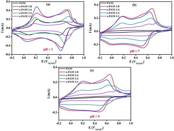 | ||
| Fig. 6 Cyclic voltammograms of PANI and c–PANI composites (a) in the electrolyte of pH 1; (b) in the electrolyte of pH 7; (c) in the electrolyte of pH 9. | ||
Generally, the electrochemical activity of the pristine PANI loses completely at pH ≥7 with disappearance of the redox peaks due to the deprotonation of PANI in neutral and base medium20,21 as shown in Fig. 6b and c. However, the c–PANI nanobrushes demonstrate a different phenomenon with the pristine PANI when pH ≥7. In neutral medium, the c–PANI composites with Wr of 1![[thin space (1/6-em)]](https://www.rsc.org/images/entities/char_2009.gif) :
:![[thin space (1/6-em)]](https://www.rsc.org/images/entities/char_2009.gif) 8, 1
8, 1![[thin space (1/6-em)]](https://www.rsc.org/images/entities/char_2009.gif) :
:![[thin space (1/6-em)]](https://www.rsc.org/images/entities/char_2009.gif) 4 and 1
4 and 1![[thin space (1/6-em)]](https://www.rsc.org/images/entities/char_2009.gif) :
:![[thin space (1/6-em)]](https://www.rsc.org/images/entities/char_2009.gif) 2 still have two obvious redox peaks. In alkaline medium, the c–PANI composites with Wr of 1
2 still have two obvious redox peaks. In alkaline medium, the c–PANI composites with Wr of 1![[thin space (1/6-em)]](https://www.rsc.org/images/entities/char_2009.gif) :
:![[thin space (1/6-em)]](https://www.rsc.org/images/entities/char_2009.gif) 8 and 1
8 and 1![[thin space (1/6-em)]](https://www.rsc.org/images/entities/char_2009.gif) :
:![[thin space (1/6-em)]](https://www.rsc.org/images/entities/char_2009.gif) 4 also demonstrate two pairs of redox peaks. All these results indicated that the c–PANI composites in this study demonstrate much higher electrochemical activity than CNT/PANI systems reported before in which only one pair of irregular redox peaks appeared for electrochemical response at neutral electrolytes.36,37 The superior electroactivity of the c–PANI composites in high pH environments is resulted from the novel nanobrush morphology with c-MWNTs encapsulated by PANI perfectly especially for the c–PANI composites with Wr of 1
4 also demonstrate two pairs of redox peaks. All these results indicated that the c–PANI composites in this study demonstrate much higher electrochemical activity than CNT/PANI systems reported before in which only one pair of irregular redox peaks appeared for electrochemical response at neutral electrolytes.36,37 The superior electroactivity of the c–PANI composites in high pH environments is resulted from the novel nanobrush morphology with c-MWNTs encapsulated by PANI perfectly especially for the c–PANI composites with Wr of 1![[thin space (1/6-em)]](https://www.rsc.org/images/entities/char_2009.gif) :
:![[thin space (1/6-em)]](https://www.rsc.org/images/entities/char_2009.gif) 8 and 1
8 and 1![[thin space (1/6-em)]](https://www.rsc.org/images/entities/char_2009.gif) :
:![[thin space (1/6-em)]](https://www.rsc.org/images/entities/char_2009.gif) 4. The strong interface interaction through the π–π stacking between PANI and c-MWNTs facilitate the electron delocalization, which forms doped PANI mainly by charge transfer in the process of redox.25 Unlike protonic acid doping, charge transfer doping is almost insusceptible to pH. In this specific system, both charge transfer doping and protonic acid doping exist in present c–PANI composite system. As a result, the redox peaks of the composite with Wr of 1
4. The strong interface interaction through the π–π stacking between PANI and c-MWNTs facilitate the electron delocalization, which forms doped PANI mainly by charge transfer in the process of redox.25 Unlike protonic acid doping, charge transfer doping is almost insusceptible to pH. In this specific system, both charge transfer doping and protonic acid doping exist in present c–PANI composite system. As a result, the redox peaks of the composite with Wr of 1![[thin space (1/6-em)]](https://www.rsc.org/images/entities/char_2009.gif) :
:![[thin space (1/6-em)]](https://www.rsc.org/images/entities/char_2009.gif) 1 decrease compared with PANI, and the redox peaks of all the composites still become weak with increasing pH to high value.
1 decrease compared with PANI, and the redox peaks of all the composites still become weak with increasing pH to high value.
To investigate the effect of these novel nanobrushes on the anticorrosion performance, PANI and c–PANI nanobrushes with Wr of 1![[thin space (1/6-em)]](https://www.rsc.org/images/entities/char_2009.gif) :
:![[thin space (1/6-em)]](https://www.rsc.org/images/entities/char_2009.gif) 8 were selected to fill into amine cured epoxy modified acrylic acid resin for a waterborne PANI-based coating on carbon steel. The optical micrographs of composites with different c–PANI contents are shown in Fig. 7. Obviously, c–PANI dispersed well in resin matrix with little aggregation compared (Fig. 7b–d) with that of PANI (Fig. 7a). This result indicates that the composites with nanobrush morphology of c-MWNTs encapsulated with PANI can prevent both the aggregation of c-MWNTs and PANI nanoparticles. c–PANI/epoxy coating with 3 wt% loading was used for the following electrochemical protection investigation.
8 were selected to fill into amine cured epoxy modified acrylic acid resin for a waterborne PANI-based coating on carbon steel. The optical micrographs of composites with different c–PANI contents are shown in Fig. 7. Obviously, c–PANI dispersed well in resin matrix with little aggregation compared (Fig. 7b–d) with that of PANI (Fig. 7a). This result indicates that the composites with nanobrush morphology of c-MWNTs encapsulated with PANI can prevent both the aggregation of c-MWNTs and PANI nanoparticles. c–PANI/epoxy coating with 3 wt% loading was used for the following electrochemical protection investigation.
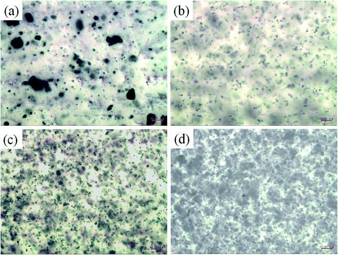 | ||
| Fig. 7 Optical micrographs of waterborne amine cured epoxy modified acrylic acid resin with PANI loading of (a) 3 wt% and c–PANI loading of (b) 1 wt%; (c) 3 wt%; (d) 5 wt%. | ||
The electrochemical behavior of the c–PANI/epoxy coatings was investigated by EIS in the mediums with different pH as shown in Fig. 8. The test of PANI/epoxy coatings are also conducted to allow a comparison. One of the electrochemical parameters to evaluate the anticorrosion properties of the coatings was the impedance modulus (|Z|0.1 Hz) at the lowest frequency (0.1 Hz).38 At the initial immersion, the |Z|0.1 Hz reflected the pore resistance of the coating resulting from water and electrolyte penetration.18 The |Z|0.1 Hz of c–PANI coating is 3.32 × 10⁸ Ω cm2, 2.04 × 10⁸ Ω cm2 and 1.81 × 10⁸ Ω cm2 after soaking in acidic, neutral and alkaline medium for 1 day while the |Z|0.1 Hz of PANI coating is 4.45 × 10⁷ Ω cm2, 3.85 × 10⁷ Ω cm2 and 3.32 × 10⁷ Ω cm2 respectively. Obviously at the initial immersion, the |Z|0.1 Hz of c–PANI coating is almost 10 times over that of PANI coating, which confirmed the improved better barrier property of c–PANI coating than pure PANI coating.
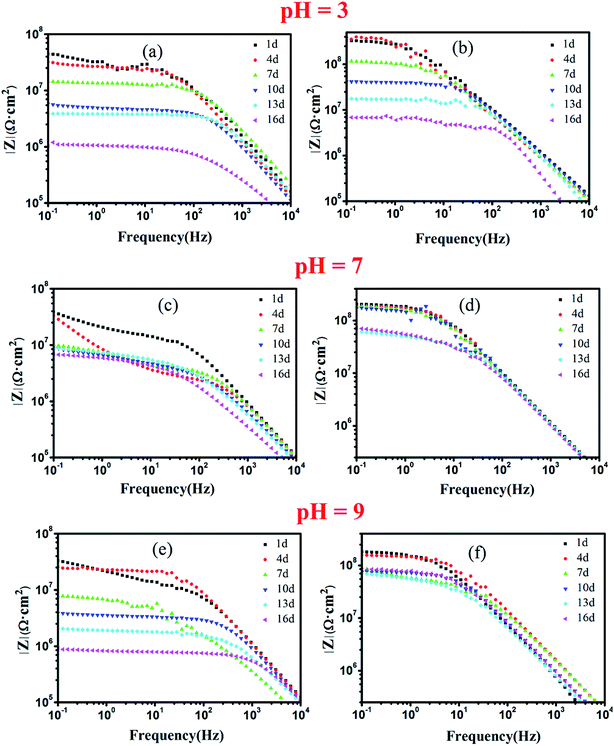 | ||
| Fig. 8 Bode plots of waterborne EA coatings filled with (a) PANI; (b) c–PANI in 3.5 wt% NaCl medium of (a, b) pH 3; (c, d) pH 7; (e, f) pH 9. | ||
In acidic medium, the |Z|0.1 Hz of PANI coating decreased with prolonging soaking days obviously. Its |Z|0.1 Hz decreased to 1.03 × 10⁶ Ω cm2 after 16 days of soaking, indicating failed protection of the coating. In contrast, the |Z|0.1 Hz of c–PANI coating in the same solution increased slightly to 3.5 × 10⁸ Ω cm2 after 4 days of soaking, and decreased to 6.83 × 10⁶ Ω cm2 at 16 days. The presence of an initial increase in the |Z|0.1 Hz value reflected significant passivation of steel occurred in the acidic medium.
In neutral medium, the |Z|0.1 Hz of PANI coating decreased with the increase of soaking time, and to 6.88 × 10⁶ Ω cm2 at 16 days; in alkaline medium, the |Z|0.1 Hz of PANI coating decreased to 9.02 × 10⁵ Ω cm2 (low than 106 Ω cm2), meaning losing the ability of corrosion protection. Although the |Z|0.1 Hz of c–PANI coating also decreased with increasing soaking time in neutral and alkaline medium, its |Z|0.1 Hz still maintains 7.21 × 10⁷ Ω cm2 and 8.72 × 10⁷ Ω cm2 after 16 days of soaking in neutral and alkaline medium respectively.
It is known that electrolyte penetrating power is strong in acidic or alkaline medium than in neutral medium. Thus the |Z|0.1 Hz will unavoidable decrease greatly as comparison in neutral medium. Generally, the relative better anticorrosion performance of PANI coating in acidic medium than that in alkaline medium should owe to the redox activity of PANI. Chen et al. have reported that the redox property of PANI, in which PANI–Emeraldine Salt (PANI–ES) could be reduced to PANI–Leucosalt (PANI–LS) through the oxidation of Fe to Fe2+ or Fe3+, and be reoxidized to PANI–ES in corrosive environment, could enhance the anticorrosion performance of coatings.17 In alkaline medium, PANI coating failed to provide corrosion protection for steel due to loss of redox activity of PANI as discussed above. However, c–PANI coating has anticorrosion performance not only in acid or neutral but also in alkaline medium. The possible explanation of the present results is the evident electroactivity of c–PANI enhanced in the medium of pH 7 and pH 9, which promote the electrochemical corrosion protection of c–PANI coating.
To further understand the corrosion protection mechanism of c–PANI, Bode plots of waterborne c–PANI coating soaked in medium with different pH by prolonging the soaking time to 35 days is shown in Fig. 9. In neutral and alkaline medium, the |Z|0.1 Hz of c–PANI coating decreases gradually with prolonging the soaking days. But |Z|0.1 Hz still remains 1.67 × 10⁷ Ω cm2 and 1.07 × 10⁷ Ω cm2 after 35 days of soaking in neutral and alkaline medium, respectively, demonstrating excellent corrosion protection behavior. This should be caused by the redox activity of c–PANI in pH 7 and 9 and the barrier property brought by the uniformly dispersion of c–PANI with nanobrush morphology.
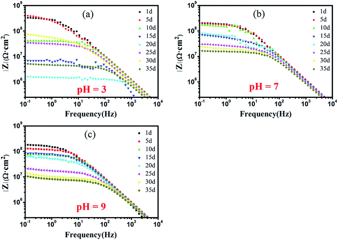 | ||
| Fig. 9 Bode plots of waterborne c–PANI coating in 3.5 wt% NaCl medium of: (a) pH 3; (b) pH 7; (c) pH 9. | ||
However, in acidic medium, the exciting result of c–PANI coating appears. The |Z|0.1 Hz decrease sharply from 3.32 × 10⁸ Ω cm2 with soaking 1 day to 1.64 × 10⁶ Ω cm2 for soaking 20 days, which may be due to the partly loss of adhesion of the coating to the metal in acidic medium. Afterward the |Z|0.1 Hz increased to 7.59 × 10⁷ Ω cm2 after 30 days of soaking and decreased again to 5.39 × 10⁶ Ω cm2 after 35 days of soaking. This variation of |Z|0.1 Hz should corresponds to passivation effect of c–PANI on metal surface, in which the electroactivity property of c–PANI could make it participate in corrosion reaction and contribute to the formation of a passivation layer on the metal surface.39
Tafel plots for PANI and c–PANI coating electrodes measured in pH 3, pH 7, and pH 9 in 3.5% NaCl aqueous solution after immersion for 16 days were shown in Fig. 10. Electrochemical corrosion measurements of coatings with PANI and c–PANI as fillers in different solution were recorded in Table 1, respectively. Generally, a higher Ecorr and a lower Icorr indicate better corrosion protection. From the Tafel curve and Table 1, high corrosion voltages and low corrosion currents can be observed in the case of coating filled with c–PANI in acidic, neutral and alkaline conditions compared with the coating PANI. The corrosion voltage and corrosion current show slightly difference between PANI and c–PANI coatings in acidic condition, but much difference in neutral and alkaline conditions. These results indicate the better corrosion protection of the coatings with c–PANI as the filler than that of the coatings filled with PANI, which is consistently with the results of Bode curve.
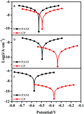 | ||
| Fig. 10 Tafel plots for PANI and c–PANI coating electrodes measured in (a) pH 3; (b) pH 7; (c) pH 9 in 3.5% NaCl aqueous solution after immersion for 16 days. | ||
| Coatings | Ecorr/V | Icorr/A cm−2 |
|---|---|---|
| PANI (pH 3) | −0.527 | 6.83 × 10⁻⁸ |
| c–PANI (pH 3) | −0.493 | 2.10 × 10⁻⁸ |
| PANI (pH 7) | −0.493 | 9.40 × 10⁻⁹ |
| c–PANI (pH 7) | −0.336 | 5.87 × 10⁻¹⁰ |
| PANI (pH 9) | −0.574 | 1.27 × 10⁻⁷ |
| c–PANI (pH 9) | −0.373 | 4.52 × 10⁻¹⁰ |
To confirm the passivation effect of c–PANI on metal surface in acid medium, XPS analysis was performed on the steel surface whose coating was peeled off after soaked for 35 days. The XPS Fe 2p spectra are shown in Fig. 11. In the case of pH 7 and pH 9, two sharp peaks appeared at 706.2 eV and 719.1 eV corresponding to Fe 2p3/2 and 2p1/2 lines of metallic iron (Fe0), respectively. Another two peaks appeared at 710.1 and 723.5 eV assignable to Fe 2p3/2 and 2p1/2 lines of trivalent iron (Fe3+) in Fe2O3, respectively.40 This result suggests that c–PANI with redox activity in the medium of pH 7 and pH 9 has good barrier property against corrosion medium penetrating, leading to no passivation effect detected. Differently, in the case of pH 3, two sharp peaks 711.2 eV and 724.5 eV appeared, and a new weak satellite feature emerged around 717 eV, indicating a dense oxide layer of Fe3O4 was formed on the steel surface, which confirm the passivation effect of c–PANI coating in acidic medium. It can be concluded that the good barrier property of c–PANI coating against neutral and alkaline corrosion medium penetrating and predominately passivation protection of c–PANI nanobrushes at acidic medium offer anticorrosion protection for steels over a wide pH range.
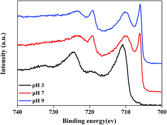 | ||
| Fig. 11 XPS Fe 2p spectra of steel surface under c–PANI coating after soaked in medium of pH 3, 7 and 9 for 35 days. | ||
4. Conclusions
The c–PANI nanobrushes with hierarchically structure have been successfully prepared by in situ oxidative polymerization of aniline in the presence of c-MWNTs. The thickness of PANI wrap can be tailored through varying the mass ratios of c-MWNTs to aniline. The unique brushes morphology of the composites leads to the formation of a new charge transfer bridge through π–π stacking and hydrogen bonding interactions, resulting in a higher electrochemical activity than PANI in acidic, neutral and alkaline environments. The anticorrosion mechanism of c–PANI containing waterborne EA coating presented excellent passivation protection for carbon steel in acidic solution and physical barrier in the neutral and alkaline solution. The novel carbon nanotube–polyaniline nanobrushes reported here offer a number of advantages, including low cost, easy performance, environmentally friendly, and high electroactivity over a wide pH range, opening any number of opportunities for application of anticorrosion protection of metals.Acknowledgements
This research was financially supported by a grant from the College and University Key Project of Jiangsu Province (No. 14KJA430006), Prospective United Innovation Project of Jiangsu Province (No. SBY2014020171), Guangdong Province Science & Technology Program (No. 2017A010103015), start-up funding from South China Agricultural University (4900-216489) and Science and Technology Cooperation Funds of Yangzhou City and Yangzhou University (YZ2016250).References
- C. O. Baker, X. W. Huang, W. Nelson and R. B. Kaner, Chem. Soc. Rev., 2017, 46, 1510–1525 RSC.
- Y. Zhang, M. A. Qiu, Y. Yu, B. Y. Wen and L. L. Cheng, ACS Appl. Mater. Interfaces, 2017, 9, 809–818 CAS.
- X. H. Sun, N. Zhang and X. Q. Huang, Chemcatchem, 2016, 8, 3436–3440 CrossRef CAS.
- G. F. Cai, J. X. Wang and P. S. Lee, Acc. Chem. Res., 2016, 49, 1469–1476 CrossRef CAS PubMed.
- M. A. Deyab, J. Power Sources, 2014, 268, 50–55 CrossRef CAS.
- B. L. He, Q. W. Tang, T. L. Liang and Q. H. Li, J. Mater. Chem. A, 2014, 2, 3119–3126 CAS.
- J. Mahmood, E. K. Lee, M. Jung, D. Shin, H. J. Choi, J. M. Seo, S. M. Jung, D. Kim, F. Li, M. S. Lah, N. Park, H. J. Shin, J. H. Oh and J. B. Baek, Proc. Natl. Acad. Sci. U. S. A., 2016, 113, 7414–7419 CrossRef CAS PubMed.
- K. Wang, Q. H. Meng, Y. J. Zhang, Z. X. Wei and M. H. Miao, Adv. Mater., 2013, 25, 1494–1498 CrossRef CAS PubMed.
- Y. Y. Yang, Y. F. Hao, J. H. Yuan, L. Niu and F. Xia, Carbon, 2014, 78, 279–287 CrossRef CAS.
- D. W. DeBerry, J. Electrochem. Soc., 1985, 132, 1022–1026 CrossRef CAS.
- J. Q. Xu, Y. Q. Zhang, D. Q. Zhang, Y. M. Tang and H. Cang, Prog. Org. Coat., 2015, 88, 84–91 CrossRef CAS.
- C. W. Peng, K. C. Chang, C. J. Weng, M. C. Lai, C. H. Hsu, S. C. Hsu, Y. Y. Hsu, W. I. Hung, Y. Wei and J. M. Yeh, Electrochim. Acta, 2013, 95, 192–199 CrossRef CAS.
- X. X. Sheng, W. X. Cai, L. Zhong, D. L. Xie and X. Y. Zhang, Ind. Eng. Chem. Res., 2016, 55, 8576–8585 CrossRef CAS.
- G. Williams and H. N. McMurray, Electrochim. Acta, 2009, 54, 4245–4252 CrossRef CAS.
- J. Fang, K. Xu, L. H. Zhu, Z. X. Zhou and H. Q. Tang, Corros. Sci., 2007, 49, 4232–4242 CrossRef CAS.
- B. Wessling and J. Posdorfer, Electrochim. Acta, 1999, 44, 2139–2147 CrossRef CAS.
- A. Talo, P. Passiniemi, O. Forsen and S. Ylasaari, Synth. Met., 1997, 85, 1333–1334 CrossRef CAS.
- Y. Chen, X. H. Wang, J. Li, J. L. Lu and F. S. Wang, Corros. Sci., 2007, 49, 3052–3063 CrossRef CAS.
- F. Chen and P. Liu, ACS Appl. Mater. Interfaces, 2011, 3, 2694–2702 CAS.
- S. L. Mu, Synth. Met., 2004, 143, 259–268 CrossRef CAS.
- S. L. Mu, Synth. Met., 2011, 161, 1306–1312 CrossRef CAS.
- S. J. Tian, A. Baba, J. Y. Liu, Z. H. Wang, W. Knoll, M. K. Park and R. Advincula, Adv. Funct. Mater., 2003, 13, 473–479 CrossRef CAS.
- E. Simon, C. M. Halliwell, C. S. Toh, A. E. G. Cass and P. N. Bartlett, J. Electroanal. Chem., 2002, 538, 253–259 CrossRef.
- J. Y. Liu, S. J. Tian and W. Knoll, Langmuir, 2005, 21, 5596–5599 CrossRef CAS PubMed.
- H. J. Zhou, Y. Q. Lin, P. Yu, L. Su and L. Q. Mao, Electrochem. Commun., 2009, 11, 965–968 CrossRef CAS.
- W. Feng, X. D. Bai, Y. Q. Lian, J. Liang, X. G. Wang and K. Yoshino, Carbon, 2003, 41, 1551–1557 CrossRef CAS.
- E. Coskun, E. A. Zaragoza-Contreras and H. J. Salavagione, Carbon, 2012, 50, 2235–2243 CrossRef CAS.
- S. Quillard, G. Louarn, S. Lefrant and A. G. Macdiarmid, Phys. Rev. B: Condens. Matter Mater. Phys., 1994, 50, 12496 CrossRef.
- Q. G. Wang, X. Qian, S. M. Wang, W. Zhou, H. Guo, X. M. Wu, J. P. Li and X. H. Wang, Synth. Met., 2015, 199, 1–7 CrossRef CAS.
- X. S. Zhou, T. B. Wu, B. J. Hu, G. Y. Yang and B. X. Han, Chem. Commun., 2010, 46, 3663–3665 RSC.
- T. M. Wu and Y. W. Lin, Polymer, 2006, 47, 3576–3582 CrossRef CAS.
- P. Kar and A. Choudhury, Sens. Actuators, B, 2013, 183, 25–33 CrossRef CAS.
- Q. Yao, L. D. Chen, W. Q. Zhang, S. C. Liufu and X. H. Chen, ACS Nano, 2010, 4, 2445–2451 CrossRef CAS PubMed.
- L. V. Lukachova, E. A. Shkerin, E. A. Puganova, E. E. Karyakina, S. G. Kiseleva, A. V. Orlov, G. P. Karpacheva and A. A. Karyakin, J. Electroanal. Chem., 2003, 544, 59–63 CrossRef CAS.
- M. A. Bavio, G. G. Acosta and T. Kessler, J. Power Sources, 2014, 245, 475–481 CrossRef CAS.
- Y. Zhou, Z. Y. Qin, L. Li, Y. Zhang, Y. L. Wei, L. F. Wang and M. F. Zhu, Electrochim. Acta, 2010, 55, 3904–3908 CrossRef CAS.
- J. Zhang, L. B. Kong, B. Wang, Y. C. Luo and L. Kang, Synth. Met., 2009, 159, 260–266 CrossRef CAS.
- X. G. Li, H. Y. Wang and M. R. Huang, Macromolecules, 2007, 40, 1489–1496 CrossRef CAS.
- A. Adhikari, P. Claesson, J. Pani, C. Leygraf, A. Deidinaitei and E. Blomberg, Electrochim. Acta, 2008, 53, 4239–4247 CrossRef CAS.
- T. Yamashita and P. Hayes, Appl. Surf. Sci., 2008, 254, 2441–2449 CrossRef CAS.
Footnote |
| † Electronic supplementary information (ESI) available. See DOI: 10.1039/c7ra05235a |
| This journal is © The Royal Society of Chemistry 2017 |

