 Open Access Article
Creative Commons Attribution 3.0 Unported Licence
A conductive carbon interlayer modified by magnetron sputtering for improved-performance lithium–sulfur batteries
Jing Zhang ab,
Heqin Li*b,
Zhiwei Linb,
Qiong Tangab,
Weiyu Qib,
Lulu Wangb,
Hao Zhengb and
Kuan Zhoub
aSchool of Electronic Science and Applied Physics, Hefei University of Technology, No. 193 Tunxi Road, Hefei, Anhui 230009, People's Republic of China. E-mail: lhqjs@hfut.edu.cn; Fax: +86-0551-62901362; Tel: +86-0551-62901362
bSchool of Materials Science and Engineering, Hefei University of Technology, Hefei, Anhui 230009, People's Republic of China
First published on 15th August 2017
Abstract
Cathode materials (S–AC) for lithium–sulfur (Li–S) batteries were synthesised with elemental sulfur (S) and activated carbon (AC). Conductive carbon films (CF1) were prepared with filter paper and aluminum (Al) thin films were plated onto the surface of the filter paper by the method of magnetron sputtering to fabricate modified carbon films (CF2). The as-prepared carbon films were applied as conductive interlayers inserted between the cathode and the separator for Li–S batteries S/AC/CF1 and S/AC/CF2. The properties of the cathode materials and the carbon interlayers were characterized by XRD and FESEM. Electrochemical performances of three Li–S batteries with and without interlayers (S/AC/CF1, S/AC/CF2 and S/AC) were determined by alternating-current impedance, cyclic voltammetry and constant-current charge and discharge. The assessment results show that S/AC/CF2 is superior to the others with an initial discharge specific capacity of 1273 mA h g−1 at a current rate of 1C. It delivered a reversible capacity of 924 mA h g−1 after 100 cycles and the coulombic efficiency after 200 cycles is still over 95%.
1. Introduction
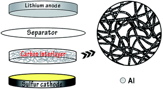
In recent years pioneering work has been conducted on the research into advanced Li–S batteries. As an attractive candidate for new rechargeable energy storage, Li–S batteries have a theoretical specific capacity of 1675 mA h g−1 with sulfur as the active material, which is highly abundant, inexpensive and non-toxic.1–3 At present there are several problems demanding a prompt solution in order to facilitate the commercialization of Li–S batteries, including the insulating properties of sulfur, the high solubility of polysulfides in the electrolyte and volumetric expansion of the redox reaction products.4–6 Researchers have made various attempts to overcome these problems such as anchoring sulfur in different conducting materials, for instance porous carbon,7–9 or wrapping sulfur particles using multiple methods,10–14 and so on. In addition, it was suggested that the electrochemical performance of Li–S batteries could be effectively improved by a porous conductive carbon film inserted between the cathode and separator as an interlayer, for the carbon film could enhance the conductivity of the sulfur cathode and intercept the diffusion of polysulfides towards the anode.15–17 Manthiram18 reported that Li–S batteries containing porous conductive carbon films delivered reversible capacities of 962 mA h g−1 after 50 cycles at 0.2C rate. Li19 fabricated an effective interlayer based on direct pyrolysis of cellulose paper for Li–S batteries which provided a discharge capacity higher than 830 mA h g−1 and an efficiency over 97% at 0.2C.The vast majority of research work lay emphasis on the modification of Li–S batteries by chemical process, nevertheless there is little attention paid to the innovation of Li–S batteries by physical methods, for example, the magnetron sputtering technique. As an developed and mature method of physical vapor deposition, magnetron sputtering has been widely applied to prepare metal, alloy and semiconductor materials on account of the merits of high rate, low temperature, good compactness and excellent adhesion between the substrates and thin films.20,21 As is reported, Zhang and coworkers22 have adopted the technique to the modification of cathode materials of lithium–sulfur batteries and a superior performance was acquired. Hu23 has utilized magnetron sputtering to prepare improved-performance all-solid lithium–sulfur batteries. In this experiment, conductive carbon films were prepared with filter paper and Al particles were deposited onto the surface of filter paper by the method of radio-frequency magnetron sputtering to obtain conductive interlayers for Li–S batteries (Fig. 1). Comparison between the batteries with and without the modified carbon interlayers was carried out to confirm the assumption that a conductive carbon interlayer may be a key to mitigate the shuttle effect and improve the cycling stability.
2. Experimental details
2.1 Preparation of S–AC cathode materials
Elemental sulfur and activated carbon (pore diameter 2.0–2.2 nm, specific surface area 1800 m2 g−1, JCNANO, Nanjing) were mixed with mass ratio of 4![[thin space (1/6-em)]](https://www.rsc.org/images/entities/char_2009.gif) :
:![[thin space (1/6-em)]](https://www.rsc.org/images/entities/char_2009.gif) 1, then grinded adequately in an agate mortar. The mixture was heated in a two-step way in a vacuum tubular furnace under flowing Ar atmosphere: firstly heated to 155 °C and kept for 6 h to make the sulfur melt fully and spread into the interspace of carbon particles, then raised to 300 °C and kept for 1 h so that the residual elemental sulfur on the AC surface could be removed. Finally, the mixture was cooled to room temperature. The as-prepared composite was mixed with acetylene black (AB) as conductive additive, polyvinylidene fluoride (PVDF) as adhesive and N-methyl-2-pyrrolidone (NMP) as solvent to synthesize cathode material S–AC, with the mass ratio of composite, AB and PVDF 7
1, then grinded adequately in an agate mortar. The mixture was heated in a two-step way in a vacuum tubular furnace under flowing Ar atmosphere: firstly heated to 155 °C and kept for 6 h to make the sulfur melt fully and spread into the interspace of carbon particles, then raised to 300 °C and kept for 1 h so that the residual elemental sulfur on the AC surface could be removed. Finally, the mixture was cooled to room temperature. The as-prepared composite was mixed with acetylene black (AB) as conductive additive, polyvinylidene fluoride (PVDF) as adhesive and N-methyl-2-pyrrolidone (NMP) as solvent to synthesize cathode material S–AC, with the mass ratio of composite, AB and PVDF 7![[thin space (1/6-em)]](https://www.rsc.org/images/entities/char_2009.gif) :
:![[thin space (1/6-em)]](https://www.rsc.org/images/entities/char_2009.gif) 2
2![[thin space (1/6-em)]](https://www.rsc.org/images/entities/char_2009.gif) :
:![[thin space (1/6-em)]](https://www.rsc.org/images/entities/char_2009.gif) 1. The mixture was fully grinded to black slurry and uniformly coated onto the Al foil with the scraper. After being fully dried at 60 °C for 6 h and pressed by twin screw roller press, the coated Al foil was cut into circular electrode slices with diameter 14 mm, sulfur content 0.86 mg cm−2, and placed in 50 °C vacuum oven.
1. The mixture was fully grinded to black slurry and uniformly coated onto the Al foil with the scraper. After being fully dried at 60 °C for 6 h and pressed by twin screw roller press, the coated Al foil was cut into circular electrode slices with diameter 14 mm, sulfur content 0.86 mg cm−2, and placed in 50 °C vacuum oven.
2.2 Magnetron sputtering deposition of Al
Filter paper was cut into circular slices with about 5 cm diameter to match the sample holders of the magnetron sputtering apparatus, immersed in ethanol and cleaned with ultrasonic washer for 15 min, then put into the air dry oven of 50 °C. After being fully dried, the slices were placed into the vacuum chamber of the ultrahigh vacuum magnetron sputtering equipment (FJL560B1, SKY Technology Development Co., Ltd. Chinese Academy of Sciences). Tiny Al particles were deposited onto the surface of filter paper slices by radio-frequency magnetron sputtering with pure Al targets (purity 99.99%) at room temperature. The base pressure of sputtering chamber was 1.0 × 10⁻⁴ Pa and the deposition was carried out in Ar atmosphere (purity 99.99%) with the flow rate of 20 mL min−1 measured accurately by the gas mass flowmeter (D08-3B/ZM, Beijing Sevenstar Huachuang Electronics Co. Ltd.). Pre-sputtering for the Al target was conducted for 15 min before deposition in order to remove the impurities on the surface of the target. The sputtering pressure was 1.0 Pa, power 25 W, and sputtering time 7 min. The sample holders rotated at a constant speed during sputtering in order to obtain a homogeneous thin film of Al.2.3 Preparation of conductive carbon interlayers
After the sputtering was accomplished, the filter paper coated with Al thin film was taken out and placed in vacuum tube oven, slowly heated to 800 °C and kept for 2 h in flowing Ar–H2 gas mixture and then cooled to room temperature to fulfill the carbonizing process. The carbonized filter paper was cut into circular slices with 14 mm diameter and placed in 50 °C vacuum oven, labeled as CF2. Carbon films without Al were prepared with filter paper by the same carbonizing method and labeled as CF1.2.4 Battery assembly
CR-2032 coin cells were assembled in dry glove box (volume fractions of H2O and O2 less than 0.1 × 10⁻⁶, Etelux Lab2000) filled with Ar, cathode material S–AC as working electrodes, lithium as counter electrode, Celgrad 2400 membrane as separator and 1 mol L−1 lithium bis(trifluoromethanesulphonyl)imide (LiTFSI)/1,2-dimethoxyethane (DME) + 1,3-dioxolane (DOL) (volume ratio 1![[thin space (1/6-em)]](https://www.rsc.org/images/entities/char_2009.gif) :
:![[thin space (1/6-em)]](https://www.rsc.org/images/entities/char_2009.gif) 1) as electrolyte, including 1.0% LiNO3 as an electrolyte additive. Carbon films CF1 and CF2 were placed respectively between the cathode and the separator and the cells were labeled as S/AC/CF1 and S/AC/CF2. The contents of Al on the filter paper and CF2 were measured to be 1.89% and 2.26%, as well as the electrical resistivity of CF1 8.47 × 10⁻² Ω cm and CF2 3.92 × 10⁻² Ω cm respectively. Coin cells S/AC without carbon films were also assembled for comparison.
1) as electrolyte, including 1.0% LiNO3 as an electrolyte additive. Carbon films CF1 and CF2 were placed respectively between the cathode and the separator and the cells were labeled as S/AC/CF1 and S/AC/CF2. The contents of Al on the filter paper and CF2 were measured to be 1.89% and 2.26%, as well as the electrical resistivity of CF1 8.47 × 10⁻² Ω cm and CF2 3.92 × 10⁻² Ω cm respectively. Coin cells S/AC without carbon films were also assembled for comparison.
2.5 Material characterization and electrochemical performance testing
X-Ray diffractometer (X'-pert PROPA Nalytical, Netherlands) was employed to analyse the structures of sublimed S, AC and S–AC cathode material with Cu Kα source (λ = 1.542 Å). The working voltage was 40 kV and the operating current was 40 mA, scanning continuously from 5° to 85° with the rate of 8° min−1. Field emission scanning electron microscope (FESEM, Hitachi SU8020) were used to characterize the morphologies of cathode material and carbon films as well as the distribution of S, C and Al. Cyclic voltammetry and alternating-current impedance were obtained on the electrochemical workstation (CHI604D, Shanghai Chenhua). The scanning voltage was ranged from 1.5 V to 3.0 V and scanning speed was 0.1 mV S−1. The alternating-current impedance frequency was ranged from 10−2 Hz to 105 Hz with the amplitude of ±5 mV. Constant current charge–discharge tests were performed on the battery performance testing system (NEWARE BTS3000).3. Results and analysis
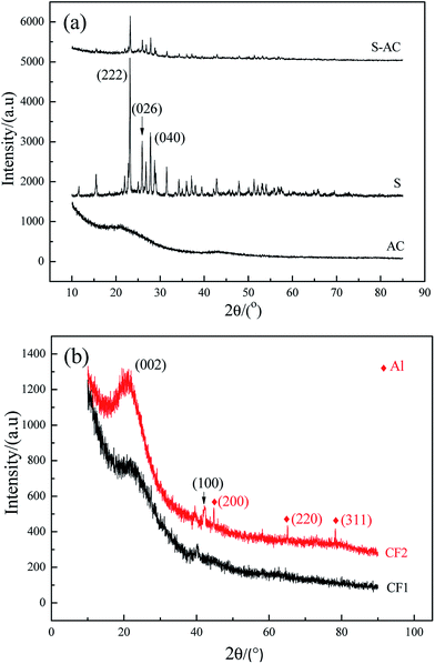
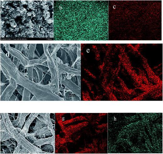
Fig. 2 is the XRD patterns of AC, elemental S and the cathode material. The amorphous AC show low and broad peaks at about 21° and 43° while elemental S presents three characteristic peaks at about 23.1°, 25.7° and 27.3° corresponding to the crystal faces (222), (026) and (040) of orthorhombic system. The diffractive peak intensity of S in S–AC was obviously weakened, which was resulted from the adsorption of elemental S into AC. As shown in Fig. 2(b), CF1 is approximatively amorphous with two bread-peaks occurring around 23° and 42° while CF2 presents an evident tendency of graphitization at approximate location, anastomosing lattice planes of (002) and (100) respectively,24 which may be the consequence of catalytic graphitization mechanism of Al on the surface of CF2.25 The diffraction peaks of Al are located at 44.7°, 65.1° and 78.2°, consistent with the crystal faces of (200), (220) and (311). The graphitization structure of CF2 and the presence of Al may lead to better conductivity and consequently superior electrochemical properties of the Li–S battery.Fig. 3 is the photographs of a filter paper slice and another one coated with Al film. After being fully carbonized, the slices appear black and dark grey respectively. Fig. 4 is FESEM patterns of S–AC cathode material and two kinds of carbon films. The conductive matrix AC has abundant interspace and large specific surface area, which will accommodate S and intermediate polysulfides. The distribution of S and C in S–AC can be discerned from Fig. 4(b) and (c). Fig. 4(d) and (e) indicate that fibers in the carbon films twine and intersect with each other, making a stockade to intercept the polysulfides diffusing to the anode and mitigate the shuttle effect. Meanwhile the interspace between the fibers ensures good flexibility and mechanical strength of the carbon films and sufficient infiltration of the electrolyte. Consequently the conductive network of carbon interlayers can maintain intact in case sulfur or polysulfides precipitate out in the carbon films. Therefore the carbon interlayers promote electronic conductivity of the sulfur cathode as well as provide adequate room for the products of redox reaction. As far as the specific conductance (3.54 × 10⁷ S m−1) of Al is concerned, S/AC/CF2 would benefit more from the excellent electronic conductivity of CF2 and advanced performances of the Li–S batteries could be expected.
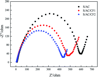
Fig. 5 demonstrates the electrochemical impedance spectroscopy before charge–discharge cycles. The first point of intersection of the semicircle in the high frequency region and abscissa axis denotes internal resistance of the batteries, which is probably determined by ionic resistance of electrolyte, intrinsic resistance of active materials and contact resistance at the interface of active material and current collector.26 The similar internal resistance of three samples reflects the approximately equal dynamics resistance of the electrochemical reaction taking place at the interface of electrode and electrolyte.27 Meanwhile the semicircle radiuses of the cells containing carbon interlayers are obviously less than that of S/AC, indicating improved charge-transfer resistance. Taking the resistivity of Al (2.83 × 10⁻⁸ Ω m) into consideration, the presence of Al on the surface of CF2 improves the conductivity of S/AC/CF2 effectively, thereby in which the electrochemical reaction takes place with the highest rate. The slopes of the inclined short lines in low frequency region are both close to 1, standing for the analogous diffusing ability of lithium ions in the solid phase.28
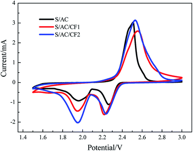
The results of CV tests are presented in Fig. 6. For the three samples, two reduction peaks of CV curves appear at about 2.2–2.3 V and 1.9–2.0 V respectively. The former is corresponding to the process in which elemental S is reduced to soluble polysulfides with long chains (Li2Sn, n ≥ 4), controlled by chemical reaction mechanism, and the latter is corresponding to the diffusion-controlled process in which polysulfides with long chains are further reduced to insoluble polysulfides (Li2S2 and Li2S) with short chains (Li2Sn, n < 4). The oxidation peak is corresponding to the oxidation processes, in which insoluble Li2S2 and Li2S are firstly oxidized to polysulfides with long chains and further to elemental S. The reduction currents of S/AC are the least in the three batteries, revealing polarization and a low reductive reaction speed.29 In comparison, the CV curve of S/AC/CF2 exhibits the greatest peak currents and largest areas of the oxidation and reduction peaks, showing the least polarization and best electrochemical properties in three batteries.30 The results of EIS and CV tests illustrate that the deposition of Al on the surface of carbon interlayer can improve the conductivity, reduce the polarization and retard shuttle effect to a certain degree.
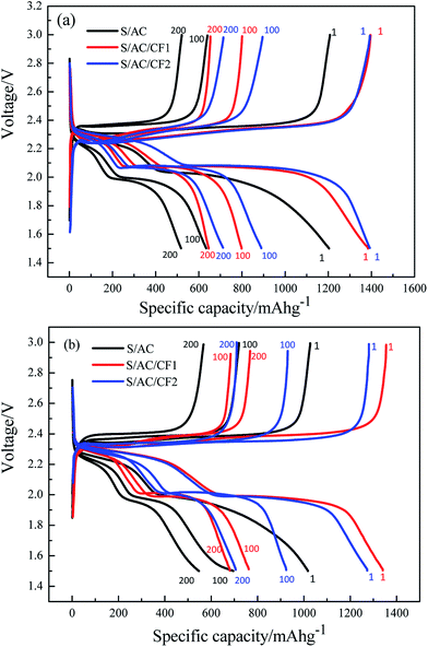
Fig. 7 describes the 1st, 100th and 200th charge and discharge characteristics of S/AC, S/AC/CF1 and S/AC/CF2 at the rate of 0.5C and 1C. Compared to the stable discharge curves and plump discharging plateaus of the batteries with carbon films, especially S/AC/CF2, S/AC presents unconspicuous plateaus and rapid-declining discharging curves, manifesting evident electrochemical polarization and shuttle effect.31 The discharging platforms of S/AC/CF1 and S/AC/CF2 occur at about 2.3 V and 2.0–2.1 V respectively, higher than those of S/AC, which proves that the network structure of carbon interlayers can significantly improve the conductivity of the electrodes and effectively prevent polysulfides from diffusing to lithium anode. At 1C rate, S/AC/CF1 presents an initial specific capacity of 1341 mA h g−1, superior to 1273 mA h g−1 of S/AC/CF2, but suffered from greater attenuation rate than S/AC/CF2. The reason may lies in two aspects, the specific conductance and malleability of Al on the surface of CF2, which may lead to excellent electrical conductivity and better mechanical strength of the interlayer thus enhance the utilization of the active material and sustain the volume expansion caused by the generation and deposition of polysulfides.32 Therefore, S/AC/CF2 should be considered to precede the other two batteries as far as the reversible capacity and cycling stability are concerned.
The specific discharge capacity and coulombic efficiency of three batteries are delineated in Fig. 8. Despite the fact that the coulombic efficiency of the three samples all precede 97% even after 200 cycles, conspicuous decrease occurs in the curves of S/AC after 150 cycles at 0.5C, and 100 cycles at 1C, whereas S/AC/CF2 exhibits the most stable curves of coulombic efficiency indicating the best cyclic reversibility and stationarity which are also confirmed by Fig. 8(c). The initial discharging specific capacities of the three batteries are 1204 mA h g−1, 1392 mA h g−1 and 1394 mA h g−1 under 0.5C, and the specific capacities after 100 cycles are 634 mA h g−1, 799 mA h g−1 and 889 mA h g−1 respectively. At the rate of 1C, S/AC/CF2 produces a specific capacity of 924 mA h g−1 in the 100th cycle representing excellent retention rate. Compared to the specific capacity retention at 0.5C, the higher one at 1C may be a direct result of the higher charge and discharge rate, which leads to insufficient time for polysulfides to dissolve and diffuse to lithium anode thus alleviates the passivation of lithium and the shuttle effect. The decline of capacity retention ratio after about 100 cycles may reflect the aggravation of electrochemical polarization and recession of the interception effect of the carbon interlayers, which may be associated with the fact that the precipitation and deposition of S and polysulfides onto the carbon interlayer increased the viscosity of the electrolyte and reduced the migration rate of the ions.33 In Fig. 8(c), S/AC/CF2 provide an initial specific capacity of 1366 mA h g−1 at 0.1C and 821 mA h g−1 after 140th cycle under variable rates, which indicates that CF2 can efficiently improve the cycle reversibility. Experimental results demonstrate that, besides enhancing the electronic conductivity of the battery ascribing the specific conductance of Al, CF2 can effectively impede polysulfides from migrating to lithium anode by the network structure thus assuage the passivation of lithium, as well as sustain the volume expansion of polysulfides by the improved mechanical strength profiting from the excellent malleability of Al, which may be the major cause of the best electrochemical performance of S/AC/CF2 among the three samples.
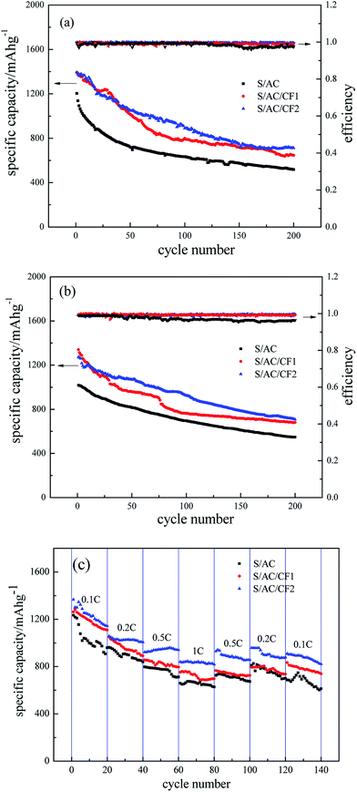 | ||
| Fig. 8 Specific capacity and coulombic efficiency curves of S/AC, S/AC/CF1 and S/AC/CF2, (a) 0.5C, (b) 1C, (c) variable rates. | ||
4. Conclusions
Conductive carbon interlayers were introduced into Li–S batteries, prepared by heating filter paper and modified by magnetron sputtering. The carbon interlayer coated by Al film reduced the internal resistance and raised the utilization of sulfur effectively. The button cell S/AC/CF2 delivered 1394 mA h g−1 and 1273 mA h g−1 respectively in the first discharging at the current rate of 0.5C and 1C, and 889 mA h g−1 and 924 m A h g−1 even after 100 cycles. The coulombic efficiency after 200 cycles is still over 95%, showing excellent capacity retention rate and stable cycle performances. The results show that it is an effective method to coat Al thin films on the surface of carbon interlayer by magnetron sputtering for modification of Li–S battery.Acknowledgements
The authors gratefully acknowledge the support of the “Student's Platform for Innovation and Entrepreneurship Training Program” of the Ministry of Education of China (No. 201710359071).References
- P. G. Bruce, S. A. Freunberger and L. J. Hardwick, Nat. Mater., 2012, 11, 19 CrossRef CAS PubMed.
- S. Evers and L. F. Nazar, Acc. Chem. Res., 2013, 46, 1135 CrossRef CAS PubMed.
- A. Fotouhi, D. J. Auger and K. Propp, Renewable Sustainable Energy Rev., 2016, 56, 1008 CrossRef CAS.
- L. Li, L. Y. Li and X. D. Guo, J. Solid State Electrochem., 2013, 17, 115 CrossRef CAS.
- B. Ding, C. Yuan and L. Shen, Chem.–Eur. J., 2013, 19, 1013 CrossRef CAS PubMed.
- S. Evers, T. Yim and L. F. Nazar, J. Phys. Chem. C, 2012, 116, 19653 CAS.
- H. H. Nersisyan, S. H. Joo and B. U. Yoo, Carbon, 2016, 103, 255 CrossRef CAS.
- J. Qu, S. Lv and X. Peng, J. Alloys Compd., 2016, 671, 17 CrossRef CAS.
- S. D. Seo, C. Choi and D. W. Kim, Mater. Lett., 2016, 172, 116 CrossRef CAS.
- L. Y. Li, X. Liu and K. Zhu, J. Solid State Electrochem., 2015, 19, 1 CrossRef.
- L. C. Smith, P. Malati and J. Fang, Mater. Horiz., 2015, 3, 137 RSC.
- D. H. Wang, D. Xie and T. Yang, J. Power Sources, 2016, 313, 233 CrossRef CAS.
- H. Y. Lee, Y. Jung and S. Kim, J. Nanosci. Nanotechnol., 2016, l16, 2692 CrossRef.
- Y. Zhang, Y. Zhao and Z. Bakenov, Ionics, 2014, 20, 1047 CrossRef CAS.
- Z. Zhang, G. Wang and Y. Lai, J. Alloys Compd., 2016, 663, 501 CrossRef CAS.
- W. Sun, X. Ou and X. Yue, Electrochim. Acta, 2016, 207, 198 CrossRef CAS.
- Y. Yang, W. Sun and J. Zhang, Electrochim. Acta, 2016, 209, 691 CrossRef CAS.
- A. Manthiram and Y. S. Su, US 20140050973 A1[P]. 2014.
- S. Li, G. Ren and M. N. F. Hoque, Appl. Surf. Sci., 2016, 396, 637 CrossRef.
- Y. Huang, H. Li and M. Zuo, J. Magn. Magn. Mater., 2016, 409, 39 CrossRef CAS.
- L. Tao, H. Li and J. Shen, J. Magn. Magn. Mater., 2015, 375, 124 CrossRef CAS.
- J. Zhang, H. Li and Q. Tang, RSC Adv., 2016, 6, 114447 RSC.
- Z. Hu, Modified Solid State Electrolyte Membrane for Lithium/Sulfur batteries [D]. National University of Defense Technology, Changsha, 2011 Search PubMed.
- T. Li, X. Yang and Z. Xu, Aerosp. Mater. Technol., 2009, 39, 76 CAS.
- H. R. Yang, X. R. Liu and J. H. Yang, J. Shanghai Inst. Chem. Technol., 2007, 1, 69 Search PubMed.
- M. Wang, H. Zhang and Y. Zhang, J. Solid State Electrochem., 2013, 17, 2243 CrossRef CAS.
- J. Brückner, S. Thieme and H. T. Grossmann, J. Power Sources, 2014, 268, 82 CrossRef.
- Z. Deng, Z. Zhang and Y. Lai, J. Electrochem. Soc., 2013, 160, A553 CrossRef CAS.
- S. H. Chung and A. Manthiram, Electrochim. Acta, 2013, 107, 569 CrossRef CAS.
- Y. V. Mikhaylik, J. R. Akridge and N. White, Solid State Ionics, 2004, 175, 243 CrossRef.
- S. Xiong, X. Kai and X. Hong, J. Natl. Univ. Def. Technol., 2012, 34, 150 CAS.
- Y. S. Su and A. Manthiram, Chem. Commun., 2012, 48, 8817 RSC.
- J. Yu, M. Zhang and F. Ding, J. Electrochem. Soc., 2014, 20, 105 CAS.
| This journal is © The Royal Society of Chemistry 2017 |

