 Open Access Article
Creative Commons Attribution 3.0 Unported Licence
Synthesis and properties of mesoporous Zn-doped Li1.2Mn0.54Co0.13Ni0.13O2 as cathode materials by a MOFs-assisted solvothermal method†
Xin Wei,
Puheng Yang,
Honglei Li,
Shengbin Wang,
Yalan Xing*,
Xin Liu and
Shichao Zhang *
*
School of Materials Science and Engineering, Beihang University, Beijing 100191, PR China. E-mail: csc@buaa.edu.cn; xingyalan@buaa.edu.cn; Fax: +86 01082338148; Tel: +86 01082339319
First published on 12th July 2017
Abstract
Mesoporous nano-microparticles lithium-rich Zn-doped Li1.2Mn0.54Co0.13Ni0.13O2 cathode materials have been synthesized by utilizing the structural characteristics of metal–organic frameworks. The electrochemical performance is improved by the substitution of an appropriate amount of Zn into the layered Li-rich Li1.2Mn0.54Ni0.13Co0.13O2 cathode material.
1. Introduction
In recent years, the applications of rechargeable lithium-ion batteries (LIBs) in electric vehicles (HEVs, PHEVs and EVs) and energy storage systems have exerted an increasing demand for electrode materials with higher energy density, higher safety and lower cost.1–3 Compared with commercial LiCoO2 cathode materials, layered Li-rich cathode materials are regarded as the most promising substitute materials. Especially, Li1.2Mn0.54Co0.13Ni0.13O2 has received much attention due to its high discharge capacity (>250 mA h g−1) and average discharge voltage of >3.5 V. However, this material suffers from initial irreversible capacity loss, poor cycling stability and rate capability. These problems hinder the commercialization of these high-energy Li-rich cathode materials. To solve these problems, nanoscale materials with shortened lithiation depths and abundant interfaces are more favorable for attaining high lithium storage capability and fast charge–discharge processes.Metal–organic frameworks (MOFs) are highly porous materials constructed by the coordination of metal ions and organic ligands. Owing to various inorganic and organic constituents, MOFs can be altered in terms of their composition, size, shape, geometry and branching modality. Recently, the MOFs utilized as energy storage materials have been exploited, especially in the field of LIBs. When used as electrodes materials for LIBs, ion transport would speed up due to the abundant pores and tunnels, which are dependent on the size of the ligands and their arrangement manner.
To date, the application of MOFs in LIBs can be classified into three types. Firstly, they can be employed as ideal precursors that can produce functional materials with attractive properties in electrochemical applications, including metal oxides and carbon materials mainly as anode materials, such as N-doped microporous carbon,4 N-doped porous carbon coated graphene sheets,5 mesoporous nanostructured Co3O4,6 CoSe@Carbon nanoboxes.7 Secondly, pristine MOFs can be utilized as cathode or anode materials in LIBs. Fe-MOFs,8 Mn-MOFs,9,10 Zn-MOFs,11 Ni-MOFs,12 Fe-MOFs,13 Co-MOFs,14 CoCOP,15 bifunctionalized MOFs,16 bimetallic MOFs.17 Thirdly, MOFs can be used as coating, largely in cathode materials, such as LiNi0.6Co0.2Mn0.2O2,18 LiCoO2,19 Li-rich layered Li[Li0.17Ni0.20Co0.05Mn0.58]O2.20
However, it is rarely used in the synthesis of lithium-rich cathode materials, because it needs a pure phase of a mixed-metal MOF as a precursor rather than mixed MOF phases. Wang et al.21 have made a pure phase of a mixed-metal MOFs, MOF-74 [M2(DOT); DOT = dioxidoterephthalate] with 2–10 different kinds of divalent metals (Mg, Ca, Sr, Ba, Mn, Fe, Co, Ni, Zn, and Cd) by using a one-pot solvothermal reaction.
We refer to this method and successfully prepare mesoporous layered Li-rich cathode materials Zn-doped Li1.2Mn0.54Co0.13Ni0.13O2. The structure, morphology and electrochemical properties were thoroughly investigated.
2. Experimental
According to Li1.2Mn0.54Ni0.13Co0.13ZnxO2 (x = 0, 0.02, 0.04), a stoichiometric ratio of Mn(NO3)2·4H2O, Co(NO3)2·6H2O, Ni(NO3)2·6H2O, Zn(NO3)2·6H2O and 2,5-dihydroxyterephthalic acid (H4DOT, DOT = 2,5-dioxidoterephthalate) as ligand were dissolved in N,N-dimethylformamide (DMF) in Teflon-lined autoclave and heated at 120 °C for 14 h. After cooling to room temperature, the precursors, brown powders, were separated by centrifugation. The filtrate was filtered in order to avoid too much loss of manganese elements. The final product Li1.2Mn0.54Ni0.13Co0.13ZnxO2 (x = 0, 0.02, 0.04) were synthesized by mixing stoichiometric of precursors and 5 mol% excess CH3COOLi·2H2O to account for evaporation of lithium at high temperature, and then the mixtures were sintered at 500 °C for 8 h in air and subsequently calcined at 900 °C for 10 h, and noted as Z0, Z2 and Z4, respectively.Thermal gravimetric analysis for Z2-precursor and mixture consisting of Z2-precursor with LiAc·2H2O were collected by using a thermal analyzer (TG, STA 449F3, NETZSCH, Germany). Samples were heated at a constant rate of 10 °C min−1 in continuous air flow atmosphere. The structures of the materials were characterized by X-ray diffraction (XRD, Rigaku D/Max-2400, Japan). The XRD spectrum was collected in the range of 2θ value from 10° to 80° with the scan rate of 4° min−1. The morphology, size and distribution were observed by field-emission scanning electron microscopy (FESEM, Hitachi S-4800, Japan). Specific surface area and pore size distribution of the powders were measured by N2 adsorption measurements.
Electrochemical properties were investigated by assembling half-cells in an argon-filled glove box (MB-10-G with TP170b/mono, MBRAUN) with lithium metal as counter and reference electrode. The electrode was prepared by spreading a mixture of 80 wt% active material, 10 wt% carbon black, and 10 wt% polyvinylidene fluoride (PVDF) with n-methyl-2-pyrrolidone (NMP) onto an Al foil current collector. The electrode was then dried at 120 °C for 10 h in a vacuum oven. The electrolyte was formed by 1 M LiPF6 dissolved in a mixture of ethylene carbonate (EC), dimethyl carbonate (DEC) and ethyl–methyl carbonate (DMC) (1![[thin space (1/6-em)]](https://www.rsc.org/images/entities/char_2009.gif) :
:![[thin space (1/6-em)]](https://www.rsc.org/images/entities/char_2009.gif) 1
1![[thin space (1/6-em)]](https://www.rsc.org/images/entities/char_2009.gif) :
:![[thin space (1/6-em)]](https://www.rsc.org/images/entities/char_2009.gif) 1 in volume). The charge–discharge measurements were galvanostatically carried out by using a battery test system (LAND CT2001A test system) in the voltage range of 2.0–4.8 V. The current at 1C corresponds to 250 mA g−1. The cyclic voltammograms (CV) were tested by using an electrochemical station (CHI660a) at a scanning rate of 0.1 mV s−1 in the voltage range of 2.0–4.8 V. The electrochemical impedance spectra (EIS) measurements were carried out at frequencies from 100 kHz to 10 mHz with amplitude of 5 mV using an electrochemical station (CHI660a). All electrochemical measurements were conducted at room temperature.
1 in volume). The charge–discharge measurements were galvanostatically carried out by using a battery test system (LAND CT2001A test system) in the voltage range of 2.0–4.8 V. The current at 1C corresponds to 250 mA g−1. The cyclic voltammograms (CV) were tested by using an electrochemical station (CHI660a) at a scanning rate of 0.1 mV s−1 in the voltage range of 2.0–4.8 V. The electrochemical impedance spectra (EIS) measurements were carried out at frequencies from 100 kHz to 10 mHz with amplitude of 5 mV using an electrochemical station (CHI660a). All electrochemical measurements were conducted at room temperature.
3. Results and discussion
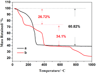
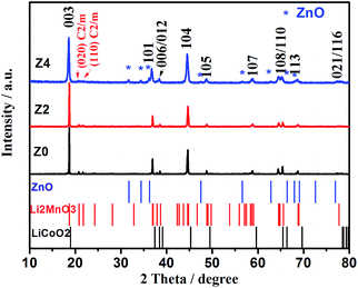
The synthesis mechanism of Li-rich cathode material is discussed by taking Z2 as an example. TG curves for Z2-precursor (a) and mixture consisting of Z2-precursor with LiAc·2H2O (b) are shown in Fig. 1. Fig. 1a shows the TG curve of the precursor of Z2. The weight loss of 60.82% (approximately 300 °C) is attributed to the decomposition of organic linkers in air and the residual weight percent is assigned to the remaining metal oxides. Fig. 1b shows the TG curve for the mixture of Z2-precursor with LiAc·2H2O, the first weight loss of 26.72% (less than 160 °C) is related with the removal of absorbed and coordinated water molecules. The second weight loss of 34.1% (160–400 °C) is associated with the decomposition of organic linkers in air and the decomposition of precursor to produce transition metal oxides. The reaction between transition metal oxides and Li salts occurred below 700 °C and the formation of Li-rich structure is accomplished above 700 °C. The results are consistent with the previous reports on the TG analysis of compound based on MOFs21 and Li-rich cathode materials.22XRD patterns of Z0, Z2 and Z4 and standard cards of ZnO, Li2MnO3 and LiCoO2 are depicted in Fig. 2. For all the three samples, main diffraction peaks can be indexed to hexagonal α-NaFeO2 structure with the R![[3 with combining macron]](https://www.rsc.org/images/entities/char_0033_0304.gif) m space group, except that the weak peaks in the 2θ range of 20–25° identified as the (020) and (110) reflection (highlighted with red letters) are attributed to the monoclinic Li2MnO3 phase (C2/m space group). The distinct splitting for two pairs of adjacent peaks (006)/(012) and (108)/(110) indicates the good structure of layered oxides. The intensity ratio of (003)/(104) more than 1.2 reflects a desired layered structure without cationic disorder.23 However, the impurity peaks of ZnO are appeared in XRD pattern of Z4 (marked with blue star). It is indicated that a part of Zn cannot enter into the lattice of Li-rich structure but exist in the form of impurities due to the excess amount of Zn. The impurity peaks of ZnO cannot be observed in XRD patterns of Z2, suggesting the appropriate doped amount of Zn.
m space group, except that the weak peaks in the 2θ range of 20–25° identified as the (020) and (110) reflection (highlighted with red letters) are attributed to the monoclinic Li2MnO3 phase (C2/m space group). The distinct splitting for two pairs of adjacent peaks (006)/(012) and (108)/(110) indicates the good structure of layered oxides. The intensity ratio of (003)/(104) more than 1.2 reflects a desired layered structure without cationic disorder.23 However, the impurity peaks of ZnO are appeared in XRD pattern of Z4 (marked with blue star). It is indicated that a part of Zn cannot enter into the lattice of Li-rich structure but exist in the form of impurities due to the excess amount of Zn. The impurity peaks of ZnO cannot be observed in XRD patterns of Z2, suggesting the appropriate doped amount of Zn.
Fig. 3 shows the morphology and distribution of precursors (a, d and g), preheating products (b, e and h) and final products (c, f and i) of Z0, Z2 and Z4, respectively. All the precursors display the uniform distribution of solid polyhedron particles with the size of less than 100 nm. The preheating products obtained after 500 °C preheating of all samples shows the homogeneous nanoparticles with the size of less than 100 nm. The final products after 900 °C heating distributes as solid polyhedron particles of the size of 500 nm with a little agglomeration. The SEM images show the uniform and not obvious difference between the morphology of three samples. The elemental mapping of sample Z2 displays the homogeneous distribution of Mn, Co, Ni and Zn elements, as shown in Fig. S1.†
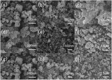 | ||
| Fig. 3 SEM images of precursors (a, d and g), preheating products (b, e and h) and final products (c, f and i) of Z0, Z2 and Z4, respectively. | ||
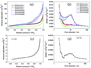
Fig. 4 shows N2 adsorption/desorption isotherms (a) and pore size distribution (b) of precursors and preheating products for Z0, Z2 and Z4, respectively. The N2 adsorption/desorption isotherms for all the samples show H3 type hysteresis loops, indicating the presence of aggregated of plate-like particles with slit shape pores.24 The specific surface areas of precursors for Z0, Z2 and Z4 are 58.48, 62.89 and 54.96 m2 g−1, respectively, with the pore size distribution of 2–4 nm. After 500 °C preheating, the specific surface areas of preheating products for Z0, Z2 and Z4 are 59.75, 55.19 and 51.23 m2 g−1, respectively, with the pore size distribution of 2–20 nm. N2 adsorption/desorption isotherms (c) and pore size distribution (d) of Z2 are also shown in Fig. 4. After 900 °C sintering, the specific surface area of Z2 is 4.67 m2 g−1 and the pore size distribution is 2–20 nm. The porous structure is also confirmed by TEM characterization, shown in Fig. S2.† The nano-micro mesoporous structure could effectively shorten the Li+ migration path and reduce the volume change during the charge–discharge cycling.25,26 Large specific surface areas increase the contact area between material and electrolyte, beneficial to the electrochemical performance.22
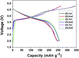
As shown in Fig. 5, all the charge–discharge profiles show typical electrochemical behavior for Z0, Z2 and Z4. During charging at a potential below 4.4 V, the capacity can be ascribed to the deintercalation of Li+ ions accompanied by concomitant oxidation of Ni2+ to Ni4+ and Co3+ to Co4+ within the active LiNi1/3Co1/3Mn1/3O2 component. The plateau above 4.5 V corresponds to the removal of lithium from the Li2MnO3 component accompanied by oxygen evolution.27 The charge capacities of Z0, Z2 and Z4 for the initial cycle are observed to be 344.9, 342.4 and 340.5 mA h g−1, respectively. These results should be attributed to the electrochemical activation of the corresponding Li2MnO3 component. The discharge capacities for the initial cycle are 248.0, 258.4, 252.0 mA h g−1, respectively. It is evident that much higher discharge capacities can be delivered by these lithium-excess manganese-based oxide electrodes based on an appropriate Zn-doped value. Zn atoms are inclined to occupy the Li sites due to the similar radius between Zn2+ (0.74 Å) and Li+ (0.76 Å) and the bond energy of Zn–O is stronger than that of Li–O,28 which is propitious to suppress the initial irreversible capacity loss.
The potential plateaus and reproducibility of the charge–discharge profiles are in good agreement with its differential capacity dQ/dV plots in Fig. 6. Two strong anodic peaks at 3.81 V and 4.49 V are derived from the oxidation of Ni2+ to Ni4+ and Co3+ to Co4+ as well as the loss of Li2O from Li2MnO3. The corresponding 4.5 V peak however cannot be found in the subsequent cycles. This indicates that Li2MnO3 will not be recovered, and the substitutional LiMnO2 → MnO2 transformation accounts for the subsequent high reversible capacity. During the discharge process, a strong peak at 3.75 V should be ascribed to the reduction of Ni4+ to Ni2+ and Co4+ to Co3+. The MnO2 → LiMnO2 transformation is responsible for the appearance of the peak at 3.28 V in the 2nd and the subsequent cycles.23,27
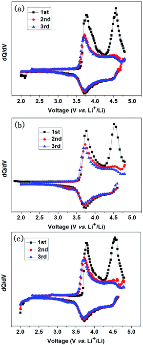 | ||
| Fig. 6 Differential capacity dQ/dV (Q: capacity; V: voltage of the cells) plots for the first 3 cycles of Z0 (a), Z2 (b) and Z4 (c) at the 0.1C rate. | ||
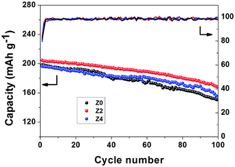
For the evaluation of cycling stability of Li-rich cathode materials, the electrodes are galvanostatically charged and discharged at 1C for 100 cycles (Fig. 7). Samples Z0, Z2 and Z4 deliver the discharge capacities of 198.4, 204.6 and 196.2 mA h g−1 in the first cycle. Z2 shows the best cycling performance, and it can maintain a discharge capacity of 167.8 mA h g−1 for the 100th cycle with the capacity retention of 82% compared with 150.8 mA h g−1 (76%) for Z0 and 153.0 mA h g−1 (78%) for Z4, respectively. The electrochemical properties are affected by both Zn-doped and the amount of Zn.
Electrochemical impedance spectroscopy (EIS) measurements of sample Z0, Z2 and Z4 were carried out after fully initial charged to 4.8 V. Nyquist plots and relevant equivalent circuit are shown in Fig. 8. In the equivalent circuit, Rs represents the resistance of the transportation of Li+ through the interfacial film, Rct refers to the charge transfer resistance, CPE means the constant phase-angle element relating to the nonideal characteristic of the double layer, Zw indicates the Warburg impedance associated with Li+ diffusion in the bulk material. As shown in Fig. 8, Nyquist plots include a semicircle at high frequency and a slope line at low frequency. The diameter of the semicircle refers to the value of charge transfer resistance (Rct). The Rct value of samples Z0, Z2 and Z4 respectively are 226.3 Ω, 118.7 Ω and 187.1 Ω. The results show that sample Z2 exhibits the smallest charge transfer resistance, indicating the smallest electrode polarization and the most easily redox reaction.
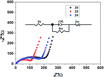 | ||
| Fig. 8 Nyquist plot and the corresponding equivalent circuit of the Li-rich cathode materials Z0, Z2 and Z4. | ||
4. Conclusions
The aforementioned electrochemical testing results indicate that, among the three samples, Z2 exhibits the highest reversible capacity and the best cycling stability as well as the smallest charge transfer resistance. The electrochemical performance is improved by the substitution of an appropriate amount of Zn into the layered Li-rich Li1.2Mn0.54Ni0.13Co0.13O2 cathode material. It is probably attributed that different amount of Zn-doped result in different degrees of homogeneous structural integration of the layered Li-rich character of Li1.2Mn0.54Ni0.13Co0.13O2. More importantly, the well-crystallized nano–micro structures, produced by MOFs-assisted solvothermal method, are advantageous for shortening the electron and lithium diffusion lengths, providing an appropriate contact area between the active materials and the electrolyte, facilitating efficient diffusion of the electrolyte into the inner regions of the electrode, and accommodating the volume changes associated with repeated Li+ insertion and extraction.Acknowledgements
This work was supported by the National Basic Research Program of China (973 Program) (2013CB934001), Beijing Natural Science Foundation (2174075), National Natural Science Foundation of China (51575030) and Key Program of Equipment Pre-Research Foundation of China (6140721020103).Notes and references
- Y. L. Xing, Y. J. Wang, C. G. Zhou, S. C. Zhang and B. Z. Fang, ACS Appl. Mater. Interfaces, 2014, 6, 2561–2567 CAS.
- B. Fang, M. S. Kim, J. H. Kim, S. Lim and J. S. Yu, J. Mater. Chem., 2010, 20, 10253–10259 RSC.
- B. Fang, J. H. Kim, M. S. Kim and J. S. Yu, Acc. Chem. Res., 2013, 46, 1397–1406 CrossRef CAS PubMed.
- F. C. Zheng, Y. Yang and Q. W. Chen, Nat. Commun., 2014, 5, 5261 CrossRef CAS PubMed.
- X. Liu, S. C. Zhang, Y. L. Xing, S. B. Wang, P. H. Yang and H. L. Li, New J. Chem., 2016, 40, 9679–9683 RSC.
- C. Li, T. Q. Chen, W. J. Xu, X. B. Lou, L. K. Pan, Q. Chen and B. W. Hu, J. Mater. Chem. A, 2015, 3, 5585–5591 CAS.
- H. Hu, J. T. Zhang, B. Y. Guan and X. W. Lou, Angew. Chem., Int. Ed., 2016, 55, 9512–9516 Search PubMed.
- G. Ferey, F. Millange, M. Morcrette, C. Serre, M. L. Doublet, J. M. Greneche and J. M. Tarascon, Angew. Chem., Int. Ed., 2007, 46, 3259–3263 CrossRef CAS PubMed.
- Z. X. Zhang, H. Yoshikawa, Z. Y. Zhang, T. Murayama, M. Sadakane, Y. Inoue, W. Ueda, K. Awaga and M. Hara, Eur. J. Inorg. Chem., 2016, 1242–1250 CrossRef CAS.
- Q. Liu, L. L. Yu, Y. Wang, Y. Z. Ji, J. Horvat, M. L. Cheng, X. Y. Jia and G. X. Wang, Inorg. Chem., 2013, 52, 2817–2822 CrossRef CAS PubMed.
- X. X. Li, F. Y. Cheng, S. N. Zhang and J. Chen, J. Power Sources, 2006, 160, 542–547 CrossRef CAS.
- T. C. An, Y. H. Wang, J. Tang, Y. Wang, L. J. Zhang and G. G. Zheng, J. Colloid Interface Sci., 2015, 445, 320–325 CrossRef CAS PubMed.
- C. Combelles and M. L. Doublet, Ionics, 2008, 14, 279–283 CrossRef CAS.
- C. Li, X. S. Hu, X. B. Lou, L. J. Zhang, Y. Wang, J. P. Amoureux, M. Shen, Q. Chen and B. W. Hu, J. Mater. Chem. A, 2016, 4, 16245–16251 CAS.
- H. W. Song, L. S. Shen, J. Wang and C. X. Wang, J. Mater. Chem. A, 2016, 4, 15411–15419 CAS.
- Y. C. Lin, Q. J. Zhang, C. C. Zhao, H. L. Li, C. L. Kong, C. Shen and L. Chen, Chem. Commun., 2015, 51, 697–699 RSC.
- C. Li, X. S. Hu, X. B. Lou, Q. Chen and B. W. Hu, Chem. Commun., 2016, 52, 2035–2038 RSC.
- S. W. Li, X. T. Fu, J. W. Zhou, Y. Z. Han, P. F. Qi, X. Gao, X. Feng and B. Wang, J. Mater. Chem. A, 2016, 4, 5823–5827 CAS.
- P. F. Qi, Y. Z. Han, J. W. Zhou, X. T. Fu, S. W. Li, J. S. Zhao, L. Wang, X. X. Fan, X. Feng and B. Wang, Chem. Commun., 2015, 51, 12391–12394 RSC.
- Q. Q. Qiao, G. R. Li, Y. L. Wang and X. P. Gao, J. Mater. Chem. A, 2016, 4, 4440–4447 CAS.
- L. J. Wang, H. X. Deng, H. Furukawa, F. Gandara, K. E. Cordova, D. Peri and O. M. Yaghi, Inorg. Chem., 2014, 53, 5881–5883 CrossRef CAS PubMed.
- J. Meng, S. C. Zhang, X. Wei, P. H. Yang, S. B. Wang, J. Wang, H. L. Li, Y. L. Xing and G. R. Liu, RSC Adv., 2015, 5, 81565–81572 RSC.
- H. L. Li, S. C. Zhang, X. Wei, P. H. Yang, Z. X. Jian and J. Meng, RSC Adv., 2016, 6, 79050–79057 RSC.
- H. Fang, S. C. Zhang, W. B. Liu, Z. J. Du, X. M. Wu and Y. L. Xing, Electrochim. Acta, 2013, 108, 651–659 CrossRef CAS.
- M. S. Kim, B. Z. Fang, J. H. Kim, D. Yang, Y. K. Kim, T. S. Bae and J. S. Yu, J. Mater. Chem., 2011, 21, 19362–19367 RSC.
- M. S. Kim, D. Bhattacharjya, B. Z. Fang, D. S. Yang, T. S. Bae and J. S. Yu, Langmuir, 2013, 29, 6754–6761 CrossRef CAS PubMed.
- J. F. Li, M. Li, L. Zhang and J. Z. Wang, J. Mater. Chem. A, 2016, 4, 12442–12450 CAS.
- J. K. Zhao, Z. X. Wang, H. J. Guo, X. H. Li, Z. J. He and T. Li, Ceram. Int., 2015, 41, 11396–11401 CrossRef CAS.
Footnote |
| † Electronic supplementary information (ESI) available. See DOI: 10.1039/c7ra05106a |
| This journal is © The Royal Society of Chemistry 2017 |

