
 Open Access Article
 This Open Access Article is licensed under a
 Creative Commons Attribution 3.0 Unported Licence
Porous carbon with large surface area derived from a metal–organic framework as a lithium-ion battery anode material†
Hai-Jun Penga,
Gui-Xia Haob,
Zhao-Hua Chub,
Yin-Wan Lina,
Xiao-Ming Lin *ac and
Yue-Peng Cai*a
*ac and
Yue-Peng Cai*a
aGuangzhou Key Laboratory of Materials for Energy Conversion and Storage, School of Chemistry and Environment, South China Normal University, Guangzhou 510006, P. R. China. E-mail: linxm@scnu.edu.cn; caiyp@scnu.edu.cn
bCollege of Chemistry and Environmental Engineering, Hanshan Normal University, Chaozhou, Guangdong 521041, P. R. China
cKey Laboratory of Theoretical Chemistry of Environment, Ministry of Education, School of Chemistry and Environment, South China Normal University, Guangzhou 510006, P. R. China
First published on 7th July 2017
Abstract
A new Cd-based metal–organic framework (Cd-MOF), namely [Cd3(TCPB)2(H2O)2(DMF)2]·7H2O, has been constructed from Cd(NO3)2 and 1,3,5-tri(4-carboxyphenoxy)benzene (H3TCPB) under solvothermal conditions. Single crystal X-ray diffraction analyses reveal that Cd-MOF displays a two-dimensional (3,6)-connected kgd net topology based on linear trinuclear Cd3(COO)6 secondary building units (SBUs) and exhibits one-dimensional opening channels. When treated as a precursor by calcining this Cd-MOF at 800 °C for 2 h, a porous carbon material was prepared. As an anode material for lithium-ion batteries (LIBs), the resulting porous carbon material exhibited an initial discharge of 2486 mA h g−1 and a charge of 1683 mA h g−1 at a current density of 300 mA g−1 with a high initial coulomb efficiency of 98%. After 300 cycles, a high reversible capacity as high as 1285 mA h g−1 could be still maintained, along with good rate capability and superior cyclic stability. The good electrochemical performance can be attributed to the unique pore structure and large surface area, which can largely offer more active sites for Li storage and cause an increase in the ability for the accumulation of charges.
Introduction
With the increasing demand for high-energy density power batteries, lithium-ion batteries (LIBs) have gained sustained research and development in recent decades.1 There is more and more interest in developing anode materials with high specific capacity and excellent cycle reversibility for next generation high-energy density rechargeable LIBs.2 Due to their good safety, stability and large electrical conductivity, porous carbonaceous composites have recently been found to have great potential as electrode materials. However, traditional commercial graphite materials with a capacity of only 372 mA h g−1 cannot meet the demands of high-energy density power batteries.3 Therefore, it still remains a challenge to find high-energy density carbon materials.Metal–organic frameworks (MOFs) with designable framework structures, tunable pore sizes and large surface area as well as facile fabrication, are emerging as a new kind of crystalline functional material and have attracted great attention in many fields, such as energy-storage systems,4 catalysis,5 drug delivery,6 chemical sensors,7 etc. MOFs have been regarded as an effective precursors or templates to construct the corresponding porous carbon materials which could be applied in energy storage devices such as lithium/sodium ion batteries8–10 and supercapacitors.11–13 For example, Pan et al. prepared porous carbon polyhedra (PCP) by directly thermal treatment of zeolitic imidazolate framework-8 (ZIF-8) for supercapacitors, which exhibits a high specific capacitance of 275.69 F g−1.14 In the latest report, Li et al. designed and synthesized a porous carbon through the vacuum pyrolysis of a Zn-based MOF at 1000 °C. And a high capacity of 2458 mA h g−1 was obtained at 0.2C.15 Based on these aforementioned studies, carbon materials derived from MOF as templates are expected to possess excellent electrochemical performance than the traditional porous carbon materials.
We have been working on crystal engineering of porous frameworks and applied for energy storage.16–19 As reported in our previous work, a porous microtube carbon was obtained by using a cadmium-based MOF (Cd-MOF) as template through directly pyrolysis, when treated as an anode materials, it displayed an improved capacity of 741 mA h g−1 and superior cyclic stability.20 As part of continuous work, herein, we synthesized a two dimensional (3,6)-connected framework with rutile topology, namely [Cd3(TCPB)2(H2O)2(DMF)2]·7H2O (H3TCPB = 1,3,5-tri(4-carboxyphenoxy)benzene). Through direct pyrolysis of this MOF, a porous carbon material was created with improved cycling stability and excellent rate capability.
Experimental section
Materials
All the reagents and solvents employed were purchased from commercial sources and used without further purification. The organic ligands 1,3,5-tri(4-carboxyphenoxy)benzene (H3TCPB, Fig. 1a) was synthesized according to a reported method.21,22 Infrared spectra were collected from KBr pellets in the range of 4000–400 cm−1 on a Nicolet/Nexus-670 FT-IR spectrometer. The elemental analyses were recorded by a PerkinElmer 240 elemental analyzer. Raman spectra were obtained on a Renishaw inVia confocal Raman microscope equipped with an argon ion laser beam. Thermogravimetric analyses (TGA) were performed on a Netzsch Thermo Microbalance TG 209 F3 Tarsus from room temperature to 900 °C with a heating rate of 10 °C min−1 under flowing nitrogen. The X-ray powder diffraction patterns were measured on a Bruker D8 Advance diffractometer at 40 kV and 40 mA with a Cu target tube and a graphite monochromator. The sorption isotherms were measured at 77 K with a Quantachrome Autosorb-iQ2-MP gas sorption analyzer. Scanning electron microscopy (SEM, ZEISS Ultra 55, Germany) operating at 5 kV was used to characterize the morphologies. X-ray photoelectron spectroscopy (XPS) spectrum was recorded on an ESCA Lab250 XPS spectrometer using Al Kα radiation.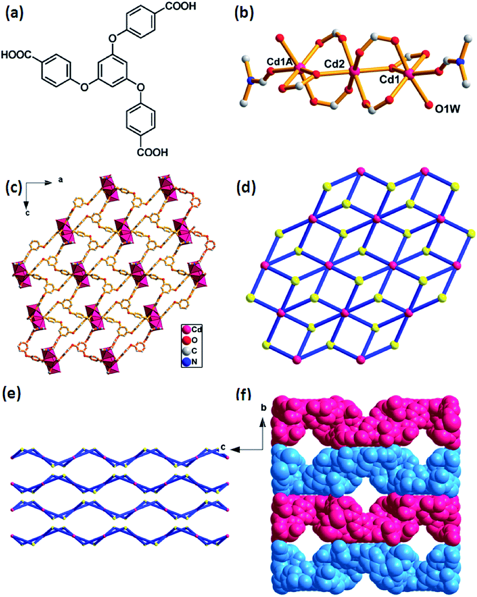 | ||
| Fig. 1 Crystal structure of Cd-MOF. (a) 1,3,5-tri(4-carboxyphenoxy)benzene, (H3TCPB). (b) Linear trinuclear cadmium clusters as a SBU. Symmetry code: (A) 1 − x, 1 − y, −z. (c) Polyhedral view of 2-D network along the b-axis. (d) View of the (3,6)-connected kgd net topology with the Schläfli symbol of (43)2(46·66·83). (e) Stacking of 2-D layers in an ABAB modes along the a-axis. (f) A space-filling view of the network between the adjacent layers (blue and pink), showing 1-D channels along a-axis. H atoms are omitted for clarity. | ||
Preparation of [Cd3(TCPB)2(H2O)2(DMF)2]·7H2O
A mixture of Cd(NO3)2·4H2O (30 mg, 0.1 mmol) and H3TCPB (25 mg, 0.05 mmol) was dissolved in 6 mL DMF and 1 mL H2O. The reaction mixture was sealed in a Teflon-lined autoclave and heated under autogenous pressure at 90 °C at a rate of 1 °C min−1 for three days. After cooling to room temperature at a rate of 0.1 °C min−1, block-shaped colorless crystals were obtained and washed with DMF. Yield: 75% (based on the ligand). Anal. calcd for C60H62N2O29Cd3 (%): C, 44.69; H, 3.88; N, 1.74. Found: C, 44.65; H, 3.86; N, 1.70. IR (KBr, cm−1): 3422(br), 1655(m), 1595(s), 1542(w), 1500(w), 1457(m), 1390(s), 1224(m), 1163(m), 1116(m), 1005(w), 868(w), 783(w).Electrochemical measurements
The porous carbon was fabricated by calcining the as-prepared Cd-MOF under the nitrogen atmosphere at 800 °C for 2 h. Then the resulting sample were washed by HF acid for 2 days, and dried under vacuum. The active carbon material, super P carbon black conductive material, and polyvinylidene fluoride (PVDF) binder in a weight ratio of 7![[thin space (1/6-em)]](https://www.rsc.org/images/entities/char_2009.gif) :2:1 was stirred together with N-methylpyrrolidone (NMP) as a solvent. The slurry was coated on a 10 μm copper foil current collector and dried at 70 °C for 18 h in a vacuum over. Subsequently, circular disks of 12 mm in diameter were cut. After that, the cells were assembled in an argon-filled glove box with the moisture and oxygen content below 0.1 ppm. The electrochemical behavior of the activated Pb-MOF material was performed using coin-type half cells (2025 type) with a Li counter electrode separated by a Celgard 2400 membrane as the separator. 1 M LiPF6 in diethyl carbonate (DEC) and ethylene carbonate (EC) (1:1 volume) formed the electrolyte. The galvanostatic charge/discharge tests were performed between 0.01 V and 3.0 V by using the LAND CT2001A multichannel battery testing system at room temperature. And the cyclic voltammetry (CV) measurements were measured on a CHI660C Electrochemical Workstation at a scan rate of 0.1 mV s−1 in a potential range of 0.01–3.0 V vs. Li/Li+.
:2:1 was stirred together with N-methylpyrrolidone (NMP) as a solvent. The slurry was coated on a 10 μm copper foil current collector and dried at 70 °C for 18 h in a vacuum over. Subsequently, circular disks of 12 mm in diameter were cut. After that, the cells were assembled in an argon-filled glove box with the moisture and oxygen content below 0.1 ppm. The electrochemical behavior of the activated Pb-MOF material was performed using coin-type half cells (2025 type) with a Li counter electrode separated by a Celgard 2400 membrane as the separator. 1 M LiPF6 in diethyl carbonate (DEC) and ethylene carbonate (EC) (1:1 volume) formed the electrolyte. The galvanostatic charge/discharge tests were performed between 0.01 V and 3.0 V by using the LAND CT2001A multichannel battery testing system at room temperature. And the cyclic voltammetry (CV) measurements were measured on a CHI660C Electrochemical Workstation at a scan rate of 0.1 mV s−1 in a potential range of 0.01–3.0 V vs. Li/Li+.
X-ray crystallographic studies
Suitable single crystal was carefully selected under an optical microscope and glued to thin glass fiber. Structural measurement was collected on an Oxford Gemini S Ultra diffractometer equipped with CuKα radiation (λ = 1.54178 Å) at 150 K by using ϕ and ω scan.23 The reflections have been corrected by empirical absorption corrections. The structures were solved by the direct method and refined by full-matrix least-squares on F2 using SHELXL programs (SHELXTL-2014).24 All non-hydrogen atoms were located successfully from Fourier maps and refined by anisotropic thermal parameters. Because there are many highly disordered solvent molecules, their diffraction contribution was removed by using the PLATON/SQUEEZE.25 Structures were then refined again using the data generated. The guest molecules can be confirmed by the TGA and elemental analyses (C, H and N). Crystallographic data for the structure is provided in Table S1† and the selected bond lengths and bond angles are listed in Table S2.†Results and discussion
Crystal structure of [Cd3(TCPB)2(H2O)2(DMF)2]·7H2O
The as-prepared Cd-MOF crystal was determined and structurally characterized by single crystal X-ray diffraction analysis as the formula [Cd3(TCPB)2(H2O)2(DMF)2]·7H2O, which was further determined by TGA and EA. Structural analyses reveal that the Cd-MOF crystallizes in orthorhombic Fddd space group and the structure contains a linear trinuclear cadmium clusters at the crystallographic inversion centre with the Cd1–Cd2 distance of 2.756 Å and the Cd1–Cd2–Cd1A bond angle of 180°. As shown in Fig. 1b, the centre Cd(2) ion exhibits an octahedral coordination surrounding by six oxygen atoms form six bridging carboxylate groups. The two terminal Cd1 and Cd1A ions reside in a distorted octahedral coordination spheres, defined by four oxygen atoms from three carboxylate groups and two oxygen atoms from ligated H2O and DMF molecules. The trinuclear cadmium clusters as secondary building units (SBUs) are united together by six ligands to generate a 2D layer structure (Fig. 2c). A better insight into the nature of this structure, the whole 2D sheet can be seen as a (3,6)-connected kgd network by simplifying the ligand as a 3-connecting node and the trinuclear cadmium clusters as a 6-connecting node (Fig. 2d). An appealing structural feature is that the 2D layers are stacked in an ABAB fashion without interpenetration (Fig. 1e), giving a 1D channel with the effective pore size of 8.7 × 8.7 Å2 (Fig. 1f). The solvent accessible volume is 3562 Å3 per unit cell, and the pore volume ration is calculated to be 32% by the PLATON program.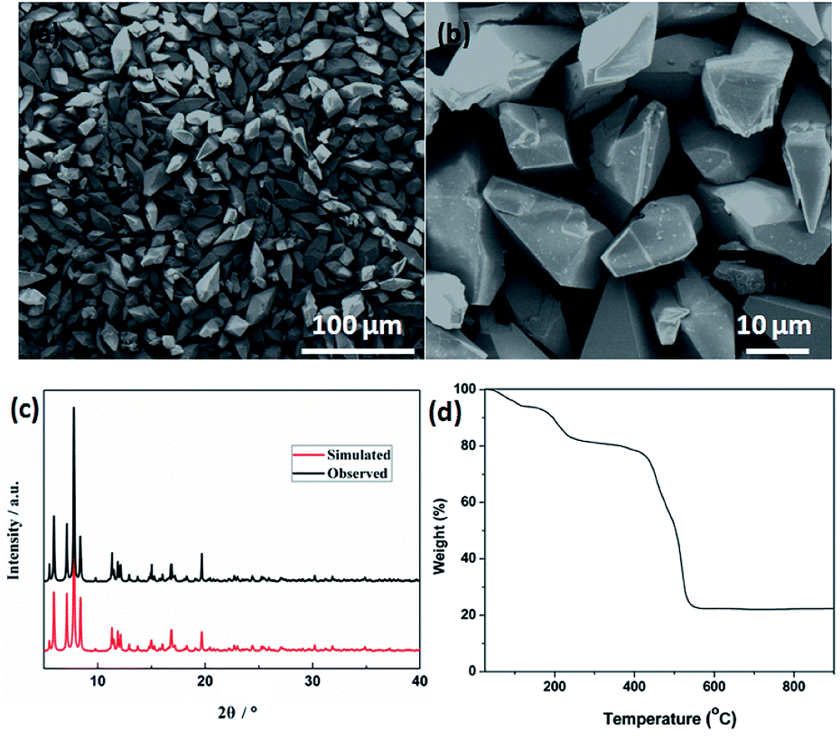 | ||
| Fig. 2 (a) Low- and (b) high-magnified FESEM images. (c) XRD pattern. (d) TGA curve of the Cd-MOF precursor. | ||
Characterization
Field emission scanning electron microscopy (FESEM) was used to investigate the sizes and morphologies of the products. As seen in Fig. 2a, the as-prepared Cd-MOF particles are relatively uniform with length and width of about 20 and 10 μm, respectively. A magnified FESEM image in Fig. 2b reveals that the surfaces of the polyhedral shape microcrystal are relatively smooth from different view angles. Infrared spectrum (IR) analysis showed that the characteristic adsorption peaks around 3300 cm−1 corresponded to the ν(OH) vibrations of the water molecules (Fig. S1†). Strong peaks at 1669 and 1394 cm−1 were assigned to asymmetric and symmetric stretching vibrations for the carboxylate groups. The XRD pattern of the as-made Cd-MOF shows that all diffraction peaks match well with the simulated pattern results (Fig. 2c), indicating the high phase purity of the samples. Thermogravimetric analysis (TGA) was also employed to examine the thermal stability under an N2 atmosphere. As shown in Fig. 2d, TGA curve shows the first weight loss from temperature to 150 °C amounting to 7.86%, which may be attributed to the loss of seven H2O guest molecules (calcd 7.82%). Then the MOF undergoes a second weight-loss step between 200 °C and 450 °C, corresponding to the loss of two coordinated H2O and DMF molecules (11.7% experimentally vs. 11.3% calculated). The framework suffers from serious weight loss upon heating to 450 °C due to the decomposition of the structure.Based on the TGA analysis, the Cd-MOF could be decomposed into CdO and porous carbon at the temperature high than 550 °C, similar decomposition behavior could be reported in the previous document.26 As a result, the Cd-MOF template was directly heated at 800 °C in nitrogen gas for 2 h. Obviously, PXRD pattern in Fig. S2† demonstrated the formation of CdO and C. Then the resulting samples were washed by HF acid to ensure the removal of the CdO composite and dried under vacuum to obtain the final product. As revealed in the FLSEM images in Fig. 3, the surface of products becomes very rough and is decorated with a number of holes, indicating the formation of pores during the calcination process. The PXRD pattern of the final product was shown in Fig. 4a. All the diffraction peaks can be assigned to the porous carbon (JCPDS no. 41-1487) with two broad peaks at 23° and 43°, corresponding to the carbon (002) and (101) peak, respectively. The XRD pattern indicates that pure porous carbon was obtained without any Cd element. Energy-dispersive X-ray spectroscopy (EDS) indicates that the product mainly contains C and O elements (Fig. S3†). The absence of the other signal further confirmed that the Cd element had been removed completely. The presence of O peak probably originated from the oxygen adsorbed in the carbon material.27 Raman spectrum shows two broad peaks centered at around 1351 cm−1 (D-bond) and 1589 cm−1 (G-bond) are also detected simultaneously (Fig. 4b), corresponding to the disordered carbon and the ordered graphitic carbon, respectively.28 The intensity of G peak is greatly enhanced than that of D peak, suggesting a great increasing degree of graphitization of the carbon in the final samples.29 X-ray photoelectron spectroscopy (XPS) spectrum verifies the existence of O and C elements in the obtained carbon (Fig. 4c). The porosity of the carbon material was further characterized by N2 adsorption–desorption isotherms. Fig. 4d indicates the presence of mesopore and macropores in the resultant materials with large hysteresis loops. The inset in Fig. 4d displays the results of a pore size analysis by applying Barrett–Joyner–Halenda (BJH) method. It is evident that the carbon material possesses two kinds of pore characteristics, including mesopores peaked at ∼46 nm and macropores centered at ∼52 nm, respectively. The Brunauer–Emmett–Teller (BET) surface is 1796 m2 g−1 with a pore volume of 2.62 cm3 g−1. There are two advantages by using Cd-MOF as precursor: (i) Cd-MOF possess abundant carbon sources, which can be transferred into carbon material after pyrolysis. (ii) The morphology remains essentially unchanged and more holes and pores formed after heating treatment. Nitrogen adsorption–desorption isotherms of Cd-MOF in Fig. S4† present the typical type I microporous behavior with the specific surface area of 348 m2 g−1. The formed carbon material shows the meso- and macro-porous structure. Such large surface provides a convenient and accessible route to electrolyte diffusion and intercalation of Li-ions, which is favorable for enhancing the electrochemical performances of the electrode.
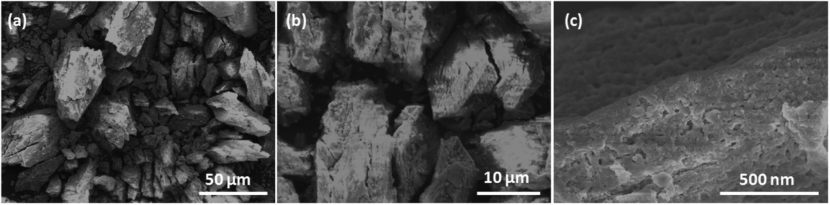 | ||
| Fig. 3 FLSEM images at different magnifications of the obtained porous carbon. | ||
 | ||
| Fig. 4 The obtained porous carbon. (a) XRD pattern, (b) Raman spectrum, (c) XPS spectrum, and (d) nitrogen adsorption–desorption isotherms (inset) pore-size distribution calculated by the BJH model. | ||
Electrochemical analysis as an anode material for LIBs
The lithium-storage properties of the as-prepared porous carbon were investigated by using the standard half-cell configuration. Fig. 5a presents the first three consecutive cyclic voltammogram (CV) curves of the electrode at a scan rate of 0.1 mV s−1 in the voltage range of 0.01–3 V vs. Li. In the first cathodic cycle, an irreversible reduction peak at around 0.60 V agrees with the irreversible reduction of electrolyte and the formation of a solid electrolyte interface (SEI) layer.30,31 A oxidation peak at approximately 1.21 V is observed during the charge process. In the subsequent two cycles, the cathodic peak disappears and the overlapping curves are found, demonstrating the electrochemical reversibility is gradually built. | ||
| Fig. 5 Electrochemical properties of the porous carbon electrode. (a) Cyclic voltammetry measurements during the first three cycles. The voltage range was from 0.01 to 3.0 V at a scan rate of 0.1 mV s−1. (b) Discharge–charge curves. The cell was tested for 300 cycles between 0.01 and 3.0 V under a current density of 300 mA g−1. (c) Cycle-life performance and coulombic efficiency at a current rate of 300 mA g−1 over 300 cycles. (d) Rate capability test at various current densities (300–3000 mA g−1). (e) Nyquist plots before and after discharge–charge cycles. The insert is the proposed equivalent circuit. | ||
Fig. 5b shows the charge–discharge voltage profiles of the porous carbon electrode at a constant current density of 300 mA g−1. The first discharge and charge capacities of the carbon electrode are 2486 and 1683 mA h g−1, respectively, leading to an initial coulombic efficiency of 68%. The large capacity loss can be attributed to the formation of a SEI film and decomposition of the electrolyte, which are common to most anode materials.32,33 Fig. 5c shows the cycling performance and corresponding coulombic efficiency at a current density of 300 mA g−1. Obviously, after a few discharge–charge cycles, the electrode exhibits excellent cyclic capacity retention and their coulombic efficiency steadily remains above 99%. At the end of 300 charge–discharge cycles, a reversible capacity of 1285 mA h g−1 can still be retained.
The rate capability of the carbon electrode is evaluated at various current densities from 300 to 3000 mA g−1, as presented in Fig. 5d. As the current density increased from 300 to 500, 800, 1000, 2000, and 3000 mA g−1, the capacity decreased slightly from 1285 to 1172, 1073, 974, 886, and 783 mA h g−1, respectively. The discharge capacity can still be recovered to almost the same value by using a small density of 300 mA g−1 after deep cycling at a high current density of up to 3000 mA g−1, indicating excellent rate capability. Such excellent capacity is higher than the theoretical value of commercial graphite (372 mA h g−1) and is superior to those previously reported carbon hybrid anode materials, such as amorphous carbon nanotubes (965 mA h g−1 at 50 mA g−1),34 carbon nanofibers (400 mA h g−1 at 200 mA g−1),35 N-doped graphene sheets (896 mA h g−1 at 50 mA g−1).36 Moreover, in comparison with other MOFs-derived porous carbon materials, our carbon electrode shows competitive reversible capacity, such as 3D porous carbon (1015 mA h g−1 at 100 mA g−1),26 N-rich carbon nanospheres (1070 mA h g−1 at 500 mA g−1),37 ZIF-8@chitosan-800N (739 mA h g−1 at 50 mA g−1),38 but less than those of other porous carbon materials such as nitrogen-doped porous carbon (2132 mA h g−1 at 100 mA g−1),39 multifractal porous carbon (2016 mA h g−1 at 74 mA g−1).40
To get further insight into lithium-storage properties, the electrochemical impedance spectra (EIS) of the obtained carbon material were investigated before and after 300th charge/discharge cycles (Fig. 5e). The two Nyquist plots exhibit similar curves consisting of a highfrequency semicircle, a medium-frequency semicircle and a low-frequency straight line, corresponding to the SEI resistance, charge-transfer resistance, and the Warburg diffusion resistance in the solid electrode materials, respectively.41–43 The depressed semicircle slightly decreases, indicating that the carbon architectures appeared to reach a stabilized state and lead to the facile charge transfer at the electrode/electrolyte interface after cycling.
Conclusions
In summary, a 2D (3,6)-connected MOF with kgd topology was obtained by application of a tritrophic ligand to assemble with Cd(II) ions. Meso- and macro-porous carbon material was successfully prepared through one-step calcination of the as-prepared MOF as template. The resultant carbon electrode exhibited high reversible specific capacity (1285 mA h g−1 at 0.3 A g−1) together with superior cyclic stability and good rate capacity. The improved lithium storage is supposed to benefit from the large accessible specific area and unique porous structures.Acknowledgements
We gratefully acknowledge the financial support from the National Natural Science Foundation of China (Grant No. 21401059 and 21471061), Science and Technology Planning Project of Guangdong Province, China (2017A010104015 and 2015B010135009), and the Innovation Project of Graduate School of South China Normal University.Notes and references
- W. Xia, A. Mahmood, R. Zou and Q. Xu, Energy Environ. Sci., 2015, 8, 1837–1866 CAS.
- M. Zhang, C. Chen, Q. Wang, W. Fu, K. Huang and W. Zhou, J. Mater. Chem. A, 2017, 5, 349–354 CAS.
- M. I. Nandasiri, S. R. Jambovane, B. P. McGrail, H. T. Schaef and S. K. Nune, Coord. Chem. Rev., 2016, 311, 38–52 CrossRef CAS.
- Y. Dou, J. Zhou, F. Yang, M.-J. Zhao, Z. Nie and J.-R. Li, J. Mater. Chem. A, 2016, 4, 12526–12534 CAS.
- Q. Xia, Y. Liu, Z. Li, W. Gong and Y. Cui, Chem. Commun., 2016, 52, 13167–13170 RSC.
- N. L. Torad, Y. Li, S. Ishihara, K. Ariga, Y. Kamachi, H.-Y. Lian, H. Hamoudi, Y. Sakka, W. Chaikittisilp, K. C. W. Wu and Y. Yamauchi, Chem. Lett., 2014, 43, 717–719 CrossRef CAS.
- L. Guang and T. H. Joseph, J. Am. Chem. Soc., 2010, 132, 7832–7833 CrossRef PubMed.
- H. Li, M. Liang, W. Sun and Y. Wang, Adv. Funct. Mater., 2016, 26, 1098–1103 CrossRef CAS.
- G. Huang, F. F. Zhang, X. C. Du, Y. L. Qin, D. M. Yin and L. M. Wang, ACS Nano, 2015, 9, 1592–1599 CrossRef CAS PubMed.
- D. Kundu, E. Talaie, V. Duffort and L. F. Nazar, Angew. Chem., Int. Ed., 2015, 54, 3431–3448 CrossRef CAS PubMed.
- W. Chaikittisilp, M. Hu, H. Wang, H. S. Huang, T. Fujita, K. C. Wu, L. C. Chen, Y. Yamauchi and K. Ariga, Chem. Commun., 2012, 48, 7259–7261 RSC.
- A. J. Amali, J. K. Sun and Q. Xu, Chem. Commun., 2014, 50, 1519–1522 RSC.
- N. L. Torad, R. R. Salunkhe, Y. Li, H. Hamoudi, M. Imura, Y. Sakka, C. C. Hu and Y. Yamauchi, Chem.–Eur. J., 2014, 20, 7895–7900 CrossRef CAS PubMed.
- Y. Liu, X. Xu, M. Wang, T. Lu, Z. Sun and L. Pan, Chem. Commun., 2015, 51, 12020–12023 RSC.
- A. Li, Y. Tong, B. Cao, H. Song, Z. Li, X. Chen, J. Zhou, G. Chen and H. Luo, Sci. Rep., 2017, 7, 40574–40582 CrossRef CAS PubMed.
- X.-M. Lin, J.-L. Niu, P.-X. Wen, Y. Pang, L. Hu and Y. P. Cai, Cryst. Growth Des., 2016, 16, 4705–4710 CAS.
- L. Hu, X.-M. Lin, J. Lin, R.-Q. Zhang, D.-L. Zhang and Y. P. Cai, CrystEngComm, 2016, 18, 9307–9315 RSC.
- X. M. Lin, T. T. Li, L. F. Chen, L. Zhang and C. Y. Su, Dalton Trans., 2012, 41, 10422–10429 RSC.
- L. Hu, X. M. Lin, J. T. Mo, J. Lin, H. L. Gan, X. L. Yang and Y. P. Cai, Inorg. Chem., 2017, 56, 4289–4295 CrossRef CAS PubMed.
- X. M. Lin, J. L. Niu, J. Lin, L. M. Wei, L. Hu, G. Zhang and Y. P. Cai, Inorg. Chem., 2016, 55, 8244–8247 CrossRef CAS PubMed.
- X. M. Lin, J. L. Niu, D. N. Chen, Y. N. Lu, G. Zhang and Y. P. Cai, CrystEngComm, 2016, 18, 6841–6848 RSC.
- X. M. Lin, T. T. Li, Y. W. Wang, L. Zhang and C. Y. Su, Chem.–Asian J., 2012, 7, 2796–2804 CrossRef CAS PubMed.
- CrysAlisCCD Version, 7, 1.171.31, Oxford Diffraction Ltd., 2006 Search PubMed.
- G. M. Sheldrick, Acta Crystallogr., Sect. C: Struct. Chem., 2015, 71, 3–8 CrossRef PubMed.
- A. L. Spek, Acta Crystallogr., Sect. C: Struct. Chem., 2015, 71, 9–18 CrossRef CAS PubMed.
- L. Zuo, S. Chen, J. Wu, L. Wang, H. Hou and Y. Song, RSC Adv., 2014, 4, 61604–61610 RSC.
- X.-M. Lin, J.-L. Niu, J. Lin, L.-M. Wei, L. Hu, G. Zhang and Y.-P. Cai, Inorg. Chem., 2016, 55, 8244–8247 CrossRef CAS PubMed.
- X. Han, W. M. Chen, X. Han, Y. Z. Tan and D. Sun, J. Mater. Chem. A, 2016, 4, 13040–13045 CAS.
- Y. Chen, X. Li, K. Park, J. Song, J. Hong, L. Zhou, Y. W. Mai, H. Huang and J. B. Goodenough, J. Am. Chem. Soc., 2013, 135, 16280–16283 CrossRef CAS PubMed.
- F. Zheng, G. Xia, Y. Yang and Q. Chen, Nanoscale, 2015, 7, 9637–9645 RSC.
- Y. Han, M. L. Zhao, L. Dong, J. M. Feng, Y. J. Wang, D. J. Li and X. F. Li, J. Mater. Chem. A, 2015, 3, 22542–22546 CAS.
- F. C. Zheng, D. Q. Zhu and Q. W. Chen, ACS Appl. Mater. Interfaces, 2014, 6, 9256–9264 CAS.
- W. M. Chen, L. Qie, Y. Shen, Y. M. Sun, L. X. Yuan, X. L. Hu, W. X. Zhang and Y. H. Huang, Nano Energy, 2013, 2, 412–418 CrossRef CAS.
- Y. Chen, Z. Lu, L. Zhou, Y. W. Mai and H. Huang, Energy Environ. Sci., 2012, 5, 7898–7902 CAS.
- C. Li, X. Yin, L. Chen, Q. Li and T. Wang, J. Phys. Chem. C, 2009, 113, 13438–13442 CAS.
- Z. S. Wu, W. Ren, L. Xu, F. Li and H. M. Cheng, ACS Nano, 2011, 5, 5463–5471 CrossRef CAS PubMed.
- Z. Xie, Z. He, X. Feng, W. Xu, X. Cui, J. Zhang, C. Yan, M. A. Carreon, Z. Liu and Y. Wang, ACS Appl. Mater. Interfaces, 2016, 8, 10324–10333 CAS.
- Y. Han, P. Qi, S. Li, X. Feng, J. Zhou, H. Li, S. Su, X. Li and B. Wang, Chem. Commun., 2014, 50, 8057–8060 RSC.
- F. Zheng, Y. Yang and Q. Chen, Nat. Commun., 2014, 5, 1–10 Search PubMed.
- A. Li, Y. Tong, B. Cao, H. Song, Z. Li, X. Chen, J. Zhou, G. Chen and H. Luo, Sci. Rep., 2017, 7, 40574–40581 CrossRef CAS PubMed.
- R. Wu, X. Qian, F. Yu, H. Liu, K. Zhou, J. Wei and Y. Huang, J. Mater. Chem. A, 2013, 1, 11126–11139 CAS.
- L. Hu and Q. W. Chen, Nanoscale, 2014, 6, 1236–1257 RSC.
- X. Yang, Y. B. Tang, X. Huang, H. T. Xue, W. P. Kang, W. Y. Li, T. W. Ng and C. S. Lee, J. Power Sources, 2015, 284, 109–114 CrossRef CAS.
Footnote |
| † Electronic supplementary information (ESI) available: CCDC 1539624. For ESI and crystallographic data in CIF or other electronic format see DOI: 10.1039/c7ra05090a |
| This journal is © The Royal Society of Chemistry 2017 |