
 Open Access Article
 This Open Access Article is licensed under a
 Creative Commons Attribution 3.0 Unported Licence
A novel ionic liquid polymer electrolyte for quasi-solid state lithium air batteries
Junjie Bai ,
Huimin Lu*,
Yuan Cao,
Xudong Li and
Junren Wang
,
Huimin Lu*,
Yuan Cao,
Xudong Li and
Junren Wang
School of Materials Science and Engineering, Beihang University, Beijing 100191, PR China. E-mail: lhm0862002@aliyun.com; Tel: +86 13331151800
First published on 14th June 2017
Abstract
Novel ionic liquid polymer electrolytes based on polymer poly(vinylidene fluoride-co-hexafluoropropylene) (PVdF-HFP), lithium bis(tri-fluoromethanesulfonyl)imide (LiTFSI) with different 1-ethyl-3-methyl-imidazolium bis(trifluoromethanesulfonyl)imide (EMITFSI) weight ratios have been synthesized and applied to quasi-solid state Li–air batteries. The morphology, electrochemical properties of prepared electrolytes, the discharge–charge capacity and cycling performance of the quasi-solid state Li–air batteries have been characterized and are discussed. Electrochemical properties of polymer electrolyte with incorporation of EMITFSI improved the electrochemical stability window (4.9 V) with higher ionic conductivity (∼4.30 × 10⁻³ S cm−1), but decreased the cationic transference number. The improvements are attributed to the reducing crystallinity of polymer matrix and formation of many homogeneous, large-size across-linked pores (60% EMITFSI), which could facilitate the transmission of Li ions. While for the quasi-solid state Li–air batteries, the ionic liquid polymer electrolyte shows good compatibility and safety with an Li anode and an air breathing cathode, significantly improved galvanostatic discharge–charge capacity and cyclic stability (without capacity fading until 20 cycles) in the capacity-controlled mode, which demonstrates that the novel ionic liquid polymer electrolyte is a potential choice for the quasi-solid state Li–air batteries for future practical applications.
1. Introduction
Lithium air batteries (LABs) have aroused the attention of energy storage researchers all over the world since the first rechargeable Li–air battery was reported by Abraham, due to its theoretical specific energy is 3505 W h kg−1, which is about 8 times higher than of lithium ion batteries.1–3 This is suitable for the battery requirements of electric vehicles (the driving distance with a single charge should be at least 300 miles).3 However, we are a long way from the practical application of Li–air technology beyond laboratory studies. Some technical difficulties still exist, such as high overpotential during the charge–discharge process, flammability, and high volatility of the liquid electrolytes.4 Besides, the formation of Li2O2 prevents further reaction in cathode. Nevertheless, there is little doubt that the LABs will be the best alternative over the lithium ion batteries in the future.5–7Electrolyte selection plays a very important role in the LABs system. At the initial stage of the studying of LABs, there has been some experimental and theoretical evidence that traditional liquid electrolytes (like the organic carbonates electrolyte) commonly used in lithium-ion batteries are not suitable for LABs due to shortcomings such as easy leakage, flammability and the corrosion of lithium metal.8–11 To solve the problems of liquid electrolytes, the researchers found gel polymer electrolyte, which consist of polymers (like poly(ethylene oxide) (PEO), poly(vinyl alcohol) (PVA), poly(methyl methacrylate) (PMMA), PVdF-HFP etc.) and ionic salts (like LiTFSI, lithium tetrafluoroborate (LiBF4), lithium hexafluorophosphate (LiPF6) etc.), combine outstanding electrochemical properties of liquid electrolytes with high safety of polymer materials. PVdF-HFP is an ideal matrix to polymer electrolyte (the polymer choice for Bellcore's plastic Li-ion batteries) because of the presence of strong electron attracting functional group (–C–F), high dielectric constant (ε = 8.4) and good mechanical properties, the functional group (–HFP) reduced crystallinity, improved the ionic conductivity. Although some PVdF-HFP-based products have been industrialized in the USA, China and Japan, electrochemical properties such as ionic conductivity still are much smaller than the traditional liquid electrolyte.11–14
It had been reported that PVdF-HFP-based polymer electrolyte containing different ionic liquids possessed excellent physical and electrochemical properties in the battery applications due to some outstanding properties of ionic liquid such as non-volatile, non-flammable, high thermal stability, wide electrochemical window and high ionic conductivity (ionic liquid increases the number of ionic transport carriers).13,15–23 Kuboki et al. studied some hydrophobic ionic liquids and suggested EMITFSI as a promising candidate of electrolyte component, besides low viscosity (only 30 cP), high ionic conductivity, it is hydrophobic, chemically stable in moist atmosphere so it can prevent the vaporization of electrolyte and the corrosion of anode (even provide stable lithium deposition/dissolution).24–26
On the basis of the above background, in this study, we synthesized the ionic liquid polymer electrolyte (the ILP-based electrolyte) by adding EMITFSI (specific volume ratio) to PVdF-HFP/LiTFSI and assembled the quasi-solid state LABs. The influence of adding different EMITFSI weight ratios to polymer electrolyte on microstructure, electrochemical properties were studied by scanning electron microscopy (SEM), electrochemical impedance spectroscopy (EIS), linear sweep voltammetry (LSV), cationic transference number, interfacial resistance of electrolyte with anode and cathode. The discharge–charge behaviours and cycling performance of the quasi-solid state LABs are aimed to investigate under a defined current density. Furthermore, polymer electrolyte without EMITFSI was used as a comparison.
2. Experimental
2.1 Materials
PVdF-HFP (Mw ∼ 400![[thin space (1/6-em)]](https://www.rsc.org/images/entities/char_2009.gif) 000) was purchased from Sigma-Aldrich (USA) and used as received. Lithium foil and LiTFSI (purity > 99%), provided by Shenzhen Kejing Technology Co. (China), are stored in the Ar-filled glove box (Mikrouna Co., China), The ionic liquid EMITFSI (purity > 99%), obtained from Shanghai Monils Chem Co. (China), was also stored in the glove box.
000) was purchased from Sigma-Aldrich (USA) and used as received. Lithium foil and LiTFSI (purity > 99%), provided by Shenzhen Kejing Technology Co. (China), are stored in the Ar-filled glove box (Mikrouna Co., China), The ionic liquid EMITFSI (purity > 99%), obtained from Shanghai Monils Chem Co. (China), was also stored in the glove box.
2.2 Electrolyte preparation and Li–air cell assembly
The ILP-based electrolytes with different EMITFSI weight ratios (Table 1) were synthesized as follows. The polymer PVdF-HFP was dissolved in N,N-dimethylformamide (DMF) and stirred for 6 h at 40 °C, then a desired amount of EMITFSI and LiTFSI were added to the solution and stirred 6 h to get homogeneous, transparent solution. At last, we poured the solution into glass and dried at 90 °C under vacuum to get flexible, self-supporting transparent membranes, we weighed electrolyte before and after drying to ensure that the solvent DMF was removed (if not, dried again). All the electrochemical cells (button battery) were assembled under the dry Ar atmosphere in the glove box (humidity < 0.01 ppm). The commercial air electrode (2.01 cm2) with gas diffusion layer (consisting of polytetrafluoroethylene (PTFE) and activated carbon), catalytic layer (MnO2) and nickel mesh was used as cathode, a lithium disk (2.01 cm2) was used as anode and the ILP-based electrolytes tested as listed above.| Sample | Weight composition (wt%) | ||
|---|---|---|---|
| PVdF-HFP (polymer) | EMITFSI (ionic liquid) | LiTFSI (Li salt) | |
| ILP0 | 80 | 0 | 20 |
| ILP1 | 60 | 20 | 20 |
| ILP2 | 40 | 40 | 20 |
| ILP3 | 20 | 60 | 20 |
2.3 Electrochemical performance measurements
All the electrochemical properties were tested in Gamry reference 3000 and Gamry interface 1000 electrochemical workstation.Electrochemical stability window was investigated by LSV at a scanning rate of 1.0 mV s−1, where SS (stainless steel) was used as working electrode and lithium was used as both counter and reference electrodes.
Ionic conductivity was measured by potentiostatic EIS with blocking cell (SS/ILP/SS) within frequency range from 0.01 Hz to 100 kHz at room temperature (298 K). The ionic conductivity (σ) was determined from the eqn (1):
 | (1) |
Cationic transference number (tLi+) of the ILP-based electrolyte was determined with symmetric cell (Li/ILP/Li) by using the combined a.c./d.c. technique.15 In this technique, the initial current (I0) and final current (ISS) can be measured, at a constant polarization voltage of 10 mV in 5000 s. The resistances of cell (before (R0) and after (RSS) polarization) were also measured by a.c. impedance spectroscopy within a frequency range from 0.01 Hz to 100 kHz at room temperature. The following eqn (2) was used for the estimation of the value of tLi+.
| tLi+ = ISS(ΔV − I0R0)/(I0(ΔV − ISSRSS)) | (2) |
Interface resistance at the lithium metal/electrode interface was measured by potentiostatic EIS with symmetric cell (Li/ILP/Li) within frequency range from 0.01 Hz to 100 kHz at the amplitude of 10 mV for a period up to 25 days (at room temperature).
2.4 Li–air battery performance test
The assembled quasi-solid state LABs were cyclically tested on LANHE CT2001A analyzer (from Wuhan LAND electronics Co., Ltd) using 0.05 mA cm−2 current density over a voltage range of 2.2–4.5 V under O2 atmosphere. The full discharge–charge performance and 10 h discharge–10 h charge performance were also tested.2.5 Microstructure characterization
Surface morphology of the ILP-based electrolyte and cathode after full discharge was studied by using SEM (JSM-7500F) with an accelerating voltage of 20 kV.3. Results and discussion
3.1 Synthesized electrolyte characterization
As mentioned in the experimental section, we synthesized the ILP-based electrolytes with different EMITFSI weight ratios through a simple casting method. With the increasing weight ratio of EMITFSI (0–60%), the electrolyte had become from a dry, white, semi-transparent, pure membrane to a flexible, little moist and transparent membrane with little glutinous grains. When we wanted to add more EMITFSI, the electrolyte membrane formation did not occur. The SEM images of the prepared electrolyte membranes are shown in Fig. 1(a)–(d). The pure PVdF-HFP/LiTFSI polymer electrolyte shows a porous structure (solvent swollen structure) composed of many spherical grains, which diameter is about 6 μm, similar to the PVdF-HFP membranes reported by other researchers.13 While the 20% EMITFSI introduced electrolyte showed a more tightly packed structure of grains and a smaller grain size (about 3–4 μm). With the further addition of EMITFSI, the crystalline grains become smaller but form more porous, as can be observed in Fig. 1(c), the membrane with 40% EMITFSI become more amorphous although the pores are small. While for the ILP3-based electrolyte (with incorporation of 60% EMITFSI), the surface of the membrane has tremendous changes compared to other ILP-based electrolyte membranes, due to the continuous decrease of polymer and the amount of ionic liquid reach the apex, therefore forming many homogeneous, large-size across-linked pores, which can facilitate the transmission of Li ions.27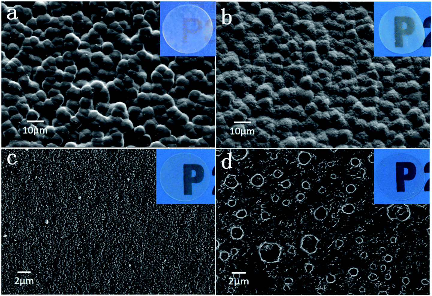 | ||
| Fig. 1 SEM images for (a) ILP0. (b) ILP1. (c) ILP2. (d) ILP3 based polymer electrolytes. Original images are shown in insets. | ||
3.2 Electrochemical performance
For practical LABs applications, we need to demonstrate various electrochemical properties of electrolyte within the limited voltage in the battery system. LSV was performed on SS/ILP/Li cells to study the electrochemical stability window of the ILP-based electrolyte with varying content of EMITFSI as shown in Fig. 2. The sudden change of anodic current represents the oxidation of TFSI− anions.6 It can be seen that the electrolyte without EMITFSI decomposes from about 3.9 V (vs. Li/Li+), while the decomposition potential of the ILP-based electrolytes increase to 4.1 V (ILP1), 4.8 V (ILP2), 4.9 V (ILP3) with the increasing amount of EMITFSI, which indicates the improvement of oxidative stability of electrolytes. This can be ascribed to the addition of EMITFSI, which makes the tighter polymer electrolyte. Besides, the LSV current has a sudden change at 2.7 V, which may correspond to the operating voltage of the cell. In fact, the electrochemical stability window of electrolytes above are all wide enough for LABs.16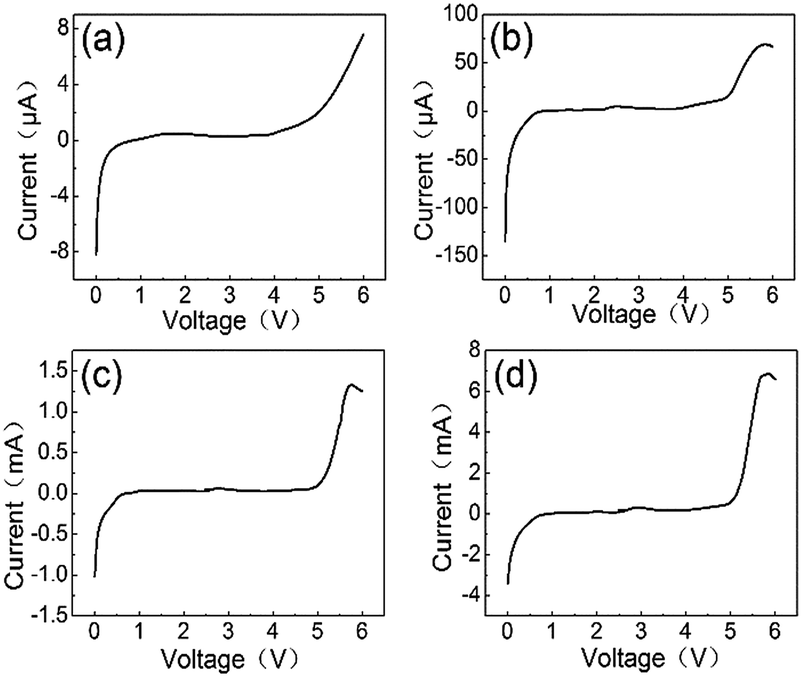 | ||
| Fig. 2 LSV of PVdF-HFP/LiTFSI/EMITFSI based polymer electrolytes: (a) ILP0. (b) ILP1. (c) ILP2. (d) ILP3. | ||
Sufficient ionic conductivity (σ) is one of the key factors for maintaining transport of lithium ions in the ILP-based electrolyte for the quasi-solid state LABs. The values of σ are presented in Table 2. The σ of pure ionic liquid EMITFSI at 298 K was ∼7.94 × 10⁻³ S cm−1 (tested by conductivity meter DDSJ-318), the σ of the ILP1-based electrolyte at 298 K is found to be ∼1.15 × 10⁻⁵ S cm−1, which is not enough for LABs applications. With the increasing concentration of EMITFSI, the σ of the ILP-based electrolyte had a drastic increment and reached a maximum value of ∼4.30 × 10⁻³ S cm−1 (the highest amount of EMITFSI) at 298 K, which is much higher than that of previous reports. The high ionic conductivity value above are ascribed to the combined effect of polymer, lithium salt, ionic liquid through the decreasing in crystallinity and the formation of more ion channels (can be seen in Fig. 1(d)), PVdF-HFP provides mechanical support and dimensional stabilization through chain entanglements and chemical cross-linking, Li salt LiTFSI has excellent properties like high salt dissociation, low lattice energy, uneasy to form ion-pairs and act as a plasticizer for polymer electrolyte (by creating free-volume) to enhance ionic mobility, ionic liquid EMITFSI functions as a plasticizer and a solvation medium for Li salt. Besides, there are literature references which document that the mixed-anion systems (i.e. Li salt and ionic liquid have different anion) possibly form contact/cross-contact ion pairs (which don't take part in the ion conduction mechanism) and decrease the ionic conductivity obviously in the system. EMITFSI and LiTFSI contain same anion TFSI−, the kind of ion and cross-contact ion pairs are less, therefore enhance the value of ionic conductivity.28
| Sample | Thickness (L)/mm | Bulk resistance (Rb)/Ω | Ionic conductivity values (σ)/S cm−1 | tLi+ |
|---|---|---|---|---|
| EMITFSI | — | — | 7.94 × 10⁻³ | — |
| ILP0 | 0.110 | 478.9 | 1.15 × 10⁻⁵ | 0.67 |
| ILP1 | 0.235 | 22.68 | 5.18 × 10⁻⁴ | 0.58 |
| ILP2 | 0.281 | 10.25 | 1.37 × 10⁻³ | 0.33 |
| ILP3 | 0.312 | 3.63 | 4.30 × 10⁻³ | 0.27 |
Ionic conductivity corresponds to the flow of three different ions (i.e. EMI+, Li+ and TFSI−) in the system, so it's important to calculate the transport number of Li+ (tLi+), which directly affect the power density of LABs by reducing the concentration of polarization. The results of chronoamperometry (CA) and EIS are shown in Fig. 3(a–d). The values of tLi+ were calculated through eqn (2) and are presented in Table 2. It can be seen that, the value of tLi+ in the system decreases with the increasing amount of EMITFSI from 0.67 (without EMITFSI) to 0.27 (with 60% EMITFSI) at room temperature. This result represents that the ionic conductivity of the system is dependent more on other ions present in the system such as the anions TFSI− ions and imidazolium cations EMI+. The decline of tLi+ in the system is inevitable because of the incursion of irrelevant ions with incorporation of EMITFSI, Li et al. also reported that the tLi+ decreases with increasing concentration of ionic liquid PYR14TFSI in the PVdF-HFP/LiTFSI/PYR14TFSI system and the value of tLi+ is 0.3 when contains 50% PYR14TFSI.29
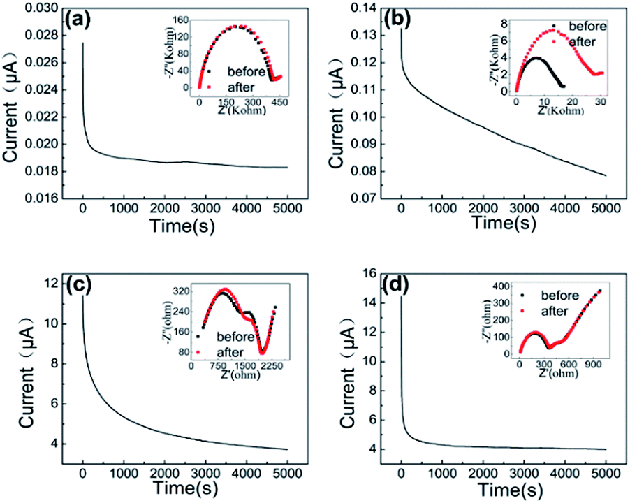 | ||
| Fig. 3 CA polarization curves and EIS plot before and after polarization (inset) of PVdF-HFP/LiTFSI/EMITFSI based polymer electrolytes: (a) ILP0. (b) ILP1. (c) ILP2. (d) ILP3. | ||
Electrochemical stability of interface between Li anode with the ILP-based electrolyte is important to cyclic stability of the quasi-solid state LABs. Electrochemical impedance evolution of Li/electrolyte (ILP-based)/Li cell at open circuit potential as a function of storage time as shown in Fig. 4, which shows typical impedance resistance patterns consisting of a semicircle at high-frequency and a short line at low-frequency. It can be seen that, the total impedance of polymer electrolyte without EMITFSI is about 60 kΩ after cell is assembled and almost unchanged within storage time of 10 d, but it increases after the 10 d to 73 kΩ after 25 d, which represent the formation of passive film on Li anode surface due to anode corrosion. While for the ILP2-based electrolyte, the initial impedance is only 550 Ω but it increases rapidly with the continuous formation of the passive film within 25 days and up to about 22 kΩ after 25 d. By comparison, the initial impedance of the ILP3-based electrolyte measured immediately after assembled is about 400 Ω and the impedance remains almost constant even after 25 days, means that there is almost no protective passive film form on Li anode, which demonstrate that electrolyte with 60% EMITFSI additions can protect Li anode well during electrochemical cycling.
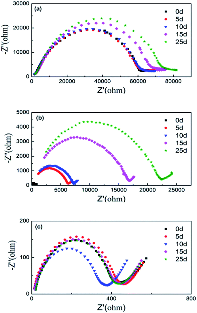 | ||
| Fig. 4 Impedance evolution of Li/electrolyte (ILP-based)/Li cell at open circuit potential as a function of storage time at room temperature: (a) ILP0. (b) ILP2. (c) ILP3. | ||
3.3 Li–air battery performance
A small current density of 0.05 mA cm−2 was adopted to research the discharge–charge performance of the quasi-solid state LABs over a voltage range of 2.2–4.5 V under O2 atmosphere. The first full discharge capacity results for ILP-based electrolytes (polymer electrolyte without EMITFSI and organic solvent can hardly discharge) are shown in Fig. 5(a), we can see that the first full discharge capacity increasing dramatically with the increasing of EMITFSI adding to electrolyte and the capacity are 0.25 mA h, 1.64 mA h, 6.13 mA h, respectively. At the same time, the full charge–discharge curves of LABs with the ILP2, ILP3-based electrolytes for 5 cycles are depicted in Fig. 5(b) and (c), which show the quasi-solid state LABs do not have stable performance for the subsequent cycles, ascribed to the combined effect of degradation of anode and blocking up of cathode. Compared to lithium ion batteries, LABs have completely different reaction mechanism and difficulties. During discharge and charge process, on the cathode, its primary discharge product (Li2O2) is insulate, insoluble (even in the organic solvents) and agglomerate, which can be seen from the SEM images of cathode after discharge. While on the anode, when we open the button battery, Li anode has been corroded to power materials. These problems result in high overpotential upon charging, seriously affected the battery capacity at deep discharge and cycle performance in spite of the initial discharge capacity has been improved greatly by using the ILP-based electrolyte.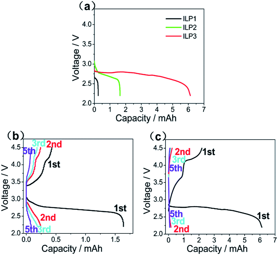 | ||
| Fig. 5 (a) The first full discharge capacity curve for the Li–air batteries with ILP-based electrolytes. (b) and (c) The full discharge–charge curves for 5 cycles of Li–air batteries with ILP2, ILP3 electrolytes, cycled at 0.05 mA cm−2 between 2.2 V and 4.5 V. | ||
For the reason above, capacity-limited tests have been proposed by different researchers and considered to be an acceptable method in line with the reaction mechanism and the configuration of LABs.11 Fig. 6 shows voltage-capacity characteristics of the ILP2 and ILP3-based electrolyte at the state of 10 h charge–10 h discharge. As can be concluded, the stability of LABs is significantly enhanced and the cycle ability improved especially for the ILP3-based electrolyte. These discharge plateau characteristics are exhibited at around 2.5 V to 2.7 V, but the ILP2-based electrolyte's discharge plateau drop obviously during cycling, causing the overpotential of oxygen reduction reaction (ORR) and oxygen evolution reaction (OER) rise, which indicate that battery's polarization (for charge and discharge) become serious especially after 5th cycle. By comparison, the ILP3-based electrolyte with 60% EMITFSI addition has lower and more stable overpotential even after 20th cycle, its polarization gap is steady (around 1.2 V) between charge of 3.8 V and discharge of 2.6 V during 10 cycles, and show almost all of its capacity fading at the 25th cycle (can hardly be avoided in prolonged cycling). These can be ascribed to the formation of more ionic channels and Li anode protection (can be seen from Fig. 4) of electrolyte with 60% EMITFST, which provide more reaction sites and weaken the polarization of the battery. So as we can conclude from the present results, the safety quasi-solid state LABs performance can be improved greatly by incorporating 60% EMITFSI in polymer electrolyte. Compared with the relevant liquid electrolyte (LiTFSI + EMITFSI), Li–air battery with the ILP3-based electrolyte has better cycling performance and is safer with the same discharge capacity (about 6 mA h), which are presented in Table 3.30
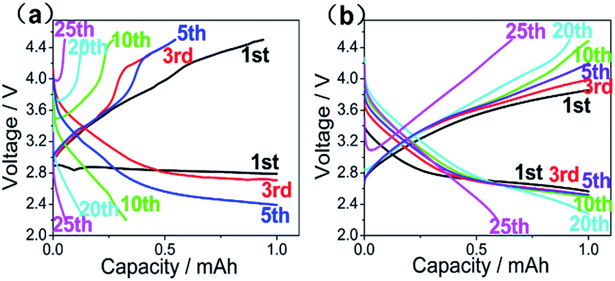 | ||
| Fig. 6 The discharge–charge curves of LABs with (a) ILP2. (b) ILP3 electrolytes (10 h charge–10 h discharge), cycled at 0.05 mA cm−2 between 2 V and 4.5 V. | ||
| Electrolyte | Discharge capacity (mA h) | Cycling number (capacity-limited) |
|---|---|---|
| EMITFSI + LiTFSI | 6.4 | 1 |
| EMITFSI + LiTFSI + 0.1% PEO | 6.1 | 2 |
| EMITFSI + LiTFSI + 0.1% PVDF | 6.5 | 10 |
| The ILP3-based | 6.1 | 20 |
In order to evaluate the chemical and discharge products variations, SEM micrographs of the air breathing cathode pristine and after full discharge are shown in Fig. 7. As we can see, pristine cathode electroactive material have a morphology of flat flakes (Fig. 7(a)), compared with it, the air breathing cathode surfaces after full discharge are covered by a layer of reaction product, which are believed to be mainly Li2O2 phase and some Li2O, Li2CO3 phases, it is similar to the morphology of Li2O2 reported by Marinaro et al.31: hollow structure with a smooth surface and nodular morphology, a range of 200–350 nm of dimension. For the ILP1-based electrolyte, the discharge product after full discharge are very few and don't clog the air breathing cathode, so we speculate that the blocking of ion channels in the electrolyte by nonconductive Li2O2 lead to the failure of further discharge processes. While for the ILP2-based electrolyte and especially the ILP3-based electrolyte, there are more discharge product accumulate on the cathode, which even block the pores of cathode, result in the rapid capacity decrease in the further discharge step, on the other hand, it means that the ILP3-based electrolyte shows good compatibility with air breathing cathode and allows more solid Li2O2 exist and accumulate.
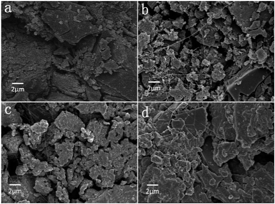 | ||
| Fig. 7 SEM morphologies of cathode of LABs with different ILP-based electrolyte after full discharge: (a) pristine. (b) ILP1. (c) ILP2. (d) ILP3. | ||
4. Conclusions
In this paper, we have shown the preparation of the novel flexible polymer electrolytes with different incorporation of EMITFSI and assembled the quasi-solid state LABs; relevant characterization and performance are presented and discussed. With incorporation of more EMITFSI ionic liquid, crystallinity of the ILP-based electrolyte decrease and there form more ion channels for ion conduction, especially for the ILP3-based electrolyte, result in the wider electrochemical stability window and higher ionic conductivity (∼4.30 × 10⁻³ S cm−1), but with a decreased cationic transference number (∼0.27 for the ILP3-based electrolyte). Moreover, for the assembled quasi-solid state LABs, the ILP3-based electrolyte shows good compatibility with Li anode and air breathing cathode, which not only improves the first full discharge capacity dramatically, but also reduces the overpotential and has almost no capacity fading until 20th cycle in the capacity-controlled mode.So as it can be concluded that the novel polymer electrolyte with incorporation of EMITFSI ionic liquid (especially for 60% addition) has excellent electrochemical performance, greatly improves the charge and discharge capacity and cycling performance of the quasi-solid state LABs, suggests realistic strategies of the quasi-solid state LABs for future practical applications. However, the ILP-based electrolyte is still in its preliminary stage, the Li+ transport number and cyclic stability need to be enhanced in subsequent work (such as the incorporation of alternative electrocatalysts).
References
- K. Abraham and Z. Jiang, J. Electrochem. Soc., 1996, 143, 1–5 CrossRef CAS.
- D. Capsoni, M. Bini, S. Ferrari, E. Quartarone and P. Mustarelli, J. Power Sources, 2012, 220, 253–263 CrossRef CAS.
- P. G. Bruce, S. A. Freunberger, L. J. Hardwick and J.-M. Tarascon, Nat. Mater., 2012, 11, 19–29 CrossRef CAS PubMed.
- J. Lu, L. Li, J.-B. Park, Y.-K. Sun, F. Wu and K. Amine, Chem. Rev., 2014, 114, 5611–5640 CrossRef CAS PubMed.
- S. A. Freunberger, Y. Chen, Z. Peng, J. M. Griffin, L. J. Hardwick, F. Bardé, P. Novák and P. G. Bruce, J. Am. Chem. Soc., 2011, 133, 8040–8047 CrossRef CAS PubMed.
- J. Yi, X. Liu, S. Guo, K. Zhu, H. Xue and H. Zhou, ACS Appl. Mater. Interfaces, 2015, 7, 23798–23804 CAS.
- Z. Peng, S. A. Freunberger, Y. Chen and P. G. Bruce, Science, 2012, 337, 563–566 CrossRef CAS PubMed.
- B. D. McCloskey, D. Bethune, R. Shelby, G. Girishkumar and A. Luntz, J. Phys. Chem. Lett., 2011, 2, 1161–1166 CrossRef CAS PubMed.
- A. C. Luntz and B. D. McCloskey, Chem. Rev., 2014, 114, 11721–11750 CrossRef CAS PubMed.
- Y. Li, Z. Huang, K. Huang, D. Carnahan and Y. Xing, Energy Environ. Sci., 2013, 6, 3339–3345 CAS.
- H.-G. Jung, J. Hassoun, J.-B. Park, Y.-K. Sun and B. Scrosati, Nat. Chem., 2012, 4, 579–585 CrossRef CAS PubMed.
- M. Michael, M. Jacob, S. Prabaharan and S. Radhakrishna, Solid State Ionics, 1997, 98, 167–174 CrossRef CAS.
- S. Ferrari, E. Quartarone, P. Mustarelli, A. Magistris, M. Fagnoni, S. Protti, C. Gerbaldi and A. Spinella, J. Power Sources, 2010, 195, 559–566 CrossRef CAS.
- S. K. Chaurasia, R. K. Singh and S. Chandra, J. Appl. Polym. Sci., 2015, 132, 41456 Search PubMed.
- V. K. Singh and R. K. Singh, J. Mater. Chem. C, 2015, 3, 7305–7318 RSC.
- H. Ye, J. Huang, J. J. Xu, A. Khalfan and S. G. Greenbaum, J. Electrochem. Soc., 2007, 154, A1048–A1057 CrossRef CAS PubMed.
- P. Yang, W. Cui, L. Li, L. Liu and M. An, Solid State Sci., 2012, 14, 598–606 CrossRef CAS.
- C. Yuan, X. Zhu, L. Su, D. Yang, Y. Wang, K. Yang and X. Cheng, Colloid Polym. Sci., 2015, 293, 1945–1952 CAS.
- A. Lewandowski, A. Swiderska-Mocek and L. Waliszewski, Electrochim. Acta, 2013, 92, 404–411 CrossRef CAS.
- L. Sim, S. Majid and A. Arof, Electrochim. Acta, 2014, 123, 190–197 CrossRef CAS.
- J.-K. Kim, A. Matic, J.-H. Ahn and P. Jacobsson, J. Power Sources, 2010, 195, 7639–7643 CrossRef CAS.
- J. Fuller, A. Breda and R. Carlin, J. Electrochem. Soc., 1997, 144, L67–L70 CrossRef CAS.
- A. Lewandowski and A. Świderska-Mocek, J. Power Sources, 2009, 194, 601–609 CrossRef CAS.
- T. Kuboki, T. Okuyama, T. Ohsaki and N. Takami, J. Power Sources, 2005, 146, 766–769 CrossRef CAS.
- P. Bonhote, A.-P. Dias, N. Papageorgiou, K. Kalyanasundaram and M. Grätzel, Inorg. Chem., 1996, 35, 1168–1178 CrossRef CAS PubMed.
- P. C. Howlett, D. R. MacFarlane and A. F. Hollenkamp, Electrochem. Solid-State Lett., 2004, 7, A97–A101 CrossRef CAS.
- S.-H. Yeon, K.-S. Kim, S. Choi, J.-H. Cha and H. Lee, J. Mater. Chem. B, 2005, 109, 17928–17935 CAS.
- S. Chaurasia, R. Singh and S. Chandra, J. Mater. Chem. B, 2013, 117, 897–906 Search PubMed.
- L. Li, J. Wang, P. Yang, S. Guo, H. Wang, X. Yang, X. Ma, S. Yang and B. Wu, Electrochim. Acta, 2013, 88, 147–156 CrossRef CAS.
- M. Tokur, H. Algul, S. Ozcan, T. Cetinkaya, M. Uysal, M. O. Guler and H. Akbulut, Solid State Ionics, 2016, 286, 51–56 CrossRef CAS.
- M. Marinaro, S. K. E. Moorthy, J. Bernhard, L. Jörissen, M. Wohlfahrt-Mehrens and U. Kaiser, Beilstein J. Nanotechnol., 2013, 4, 665–670 CrossRef PubMed.
| This journal is © The Royal Society of Chemistry 2017 |