 Open Access Article
Microstructure evolution of novel Sn islands prepared by electrodeposition as anode materials for lithium rechargeable batteries†
Ryoung-Hee Kima,
KiTae Kimb,
Sung-Jin Lima,
Do-Hwan Nam a,
Dongwook Han
 *c and
HyukSang Kwon*a
aDepartment of Materials Science and Engineering, Korea Advanced Institute of Science and Technology, Daejeon, 34141, Republic of Korea. E-mail: hskwon@kaist.ac.kr
bDepartment Battery Research Institute LG Chem Research Park, Daejeon, 34122, Republic of Korea
cClean & Energy Materials R&D Center, Korea Automotive Technology Institute, Cheonan, 31214, Republic of Korea. E-mail: dwhan@katech.re.kr
First published on 13th June 2017
Abstract
Here, we describe the striking irreversible volume expansion of micron-sized Sn anodes for lithium rechargeable batteries during cycling with brand-new Sn islands that are prepared by electrodeposition on a Cu substrate. Exceptional changes in the internal as well as external microstructure of the electrodeposited Sn islands are demonstrated by ex situ morphological analyses. The cross sectional micrographs of the Sn islands prove the widespread formation of nano-voids within individual Sn islands after initial Li dealloying followed by their enrichment during the subsequent cycles. These widespread voids and the following dead volume formed inside the Sn islands induce irreversible volume expansion in the micron-sized Sn anodes, thereby deteriorating the cycling performance of the Sn anodes.
Introduction
Sn-based anode materials have been considered as an alternative to commercial graphite anode materials for lithium rechargeable batteries owing to the higher theoretical capacity of Sn (991 mA h g−1) compared with graphite (372 mA h g−1).1–3 Considerable improvements in the electrochemical performance of the materials have been achieved by reducing the particle size of Sn to the nanoscale, alloying with other compatible metals, and combining with inactive buffer materials.4–9 However, the practical applications of the Sn-based anode materials to upcoming energy storage systems, including electric vehicles and smart grids, have suffered from their severe irreversible volume expansion caused by the repetitive alloying/dealloying with Li ions.10,11Even if it is important to mitigate the irreversible volume expansion of Sn-based anode materials, challenges still remain in the direct observation of the internal microstructure evolution in the Sn anode during cycling. The initial deformation process of micron-sized Sn particles and size-dependent pulverization mechanism of Sn particles (79–526 nm in size) were verified by an in situ X-ray transmission microscopy (TXM) and an in situ transmission electron microscopy (TEM), respectively.12,13 More recently, the microstructural changes of Sn nanowires and nano-needles during initial Li alloying/dealloying were also observed via an in situ TEM.14,15 Unfortunately, however, the transmission microscopes used in the previous research studies were not enough to trace the actual microstructure evolution of Sn anode because they could not observe the entire region of the Sn anode during long-term cycling. Instead, they primarily focused on an arbitrary single Sn particle just for the first cycle.
In this paper, we developed brand-new Sn islands on a Cu substrate by electrodeposition in a short time and observed a striking irreversible volume expansion of the Sn islands during cycling. These Sn islands independently electrodeposited on the Cu substrate could expand omnidirectionally unlike typical Sn anodes. In addition, the degradation process of Sn anode was described in detail based on the changes in morphology, phase, and resistance of the Sn islands during cycling. Importantly, the cross sectional micrographs of the Sn islands clarified that the widespread voids and the following dead volume formed inside the Sn islands induce the irreversible volume expansion of the Sn anode.
Experimental
Synthesis and physical characterization
An island-type Sn anode was electrodeposited on the matte side of a Cu foil in a 40 g L−1 SnSO4 and 150 g L−1 H2SO4 provided by ILJIN Copper Foil Co., Ltd. The island-type Sn anode was considered to be more proper to the observation of its volume expansion behavior on cycling compared with typical film-type electrodeposited Sn; the changes in the internal microstructure of Sn could be directly observed for the island-type Sn because a conductive agent and binder were excluded from the Sn anode. Cu foils were dipped in a 10 wt% H2SO4 solution for 1 min to eliminate Cu oxide films formed on the surface of Cu foils, and then used as the cathode. Galvanostatic electrodeposition was conducted in a standard three-electrode polarization cell where a pure Sn was used as the counter electrode. The Sn islands were electrodeposited for 30 s at the cathodic current density of −10 mA cm−2. The solution temperature was maintained at 30 °C during the deposition. The prepared Sn anodes were dried in a vacuum chamber for more than 10 h and then punched into a disk (1 cm2) for electrochemical tests.The physical properties of the Sn anodes (crystal structure, surface morphology, and microstructure) were observed by X-ray diffraction, scanning electron microscopy, transmission electron microscopy, and focused-ion beam spectroscopy with cycling. The Sn electrodes were washed with DMC to remove the residual Li-salts from the electrolyte before the ex situ X-ray diffraction analysis.
Electrochemical characterization
Sn/Li cells were assembled using a 2016 coin-type cell in an Ar-filled glove box. 1 M LiPF6 solution dissolved in EC![[thin space (1/6-em)]](https://www.rsc.org/images/entities/char_2009.gif) :
:![[thin space (1/6-em)]](https://www.rsc.org/images/entities/char_2009.gif) DMC (1
DMC (1![[thin space (1/6-em)]](https://www.rsc.org/images/entities/char_2009.gif) :
:![[thin space (1/6-em)]](https://www.rsc.org/images/entities/char_2009.gif) 1 volume ratio) was used as the electrolyte. Li metal foil was used as the counter electrode, and a polypropylene separator was placed between the Sn anode and Li metal foil. When the Sn anodes were discharged, a constant current density of 100 mA g−1 was applied to the cells until the voltage reached 0.005 V (vs. Li+/Li) and subsequently the constant voltage of 0.005 V (vs. Li/Li+) was retained until the capacity of 0.05C. The discharged Sn anodes were charged again at a constant current density of 100 mA g−1. The voltage polarization of the Sn anodes was observed to examine the change in the electrode resistance during 1st charge. For each step, a current density of 100 mA g−1 for 12 min followed by the rest time for 150 min was applied to measure the voltage polarization.
1 volume ratio) was used as the electrolyte. Li metal foil was used as the counter electrode, and a polypropylene separator was placed between the Sn anode and Li metal foil. When the Sn anodes were discharged, a constant current density of 100 mA g−1 was applied to the cells until the voltage reached 0.005 V (vs. Li+/Li) and subsequently the constant voltage of 0.005 V (vs. Li/Li+) was retained until the capacity of 0.05C. The discharged Sn anodes were charged again at a constant current density of 100 mA g−1. The voltage polarization of the Sn anodes was observed to examine the change in the electrode resistance during 1st charge. For each step, a current density of 100 mA g−1 for 12 min followed by the rest time for 150 min was applied to measure the voltage polarization.
Results and discussion
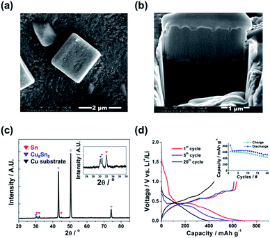
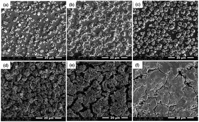
The external/internal morphology of a single Sn island prepared by an electrodeposition was observed by scanning electron microscopy (SEM) along with focused ion beam (FIB), as shown in Fig. 1a and b, respectively. The prepared Sn anode was comprised of cube-shaped Sn islands (2–3 μm in width) with no internal voids. The X-ray diffraction (XRD) pattern of the Sn anode proved the formation of polycrystalline Sn (matched to JCPDF no. 65-7657) with a minor amount of Cu6Sn5 intermediate phase at the boundary between the Sn islands and Cu substrate (Fig. 1c). In fact, the Cu6Sn5 secondary phase can be readily formed when Sn is electrodeposited on a Cu substrate even at room temperature.16,17 Meanwhile, Fig. 1d exhibits the charge/discharge profiles of the Sn anode during 1st, 5th, and 20th cycles. The initial charge (Li alloying) and discharge (Li dealloying) capacities of the Sn anode were ∼828 and ∼632 mA h g−1, respectively, which yielded a value of ∼80% for its initial coulombic efficiency. The higher initial charge capacity than discharge one possibly resulted from the formation of solid–electrolyte interface (SEI) layers on the surfaces of Sn islands during the initial charge (>0.7 V vs. Li+/Li).18 In addition, the continuous capacity degradation (inset in Fig. 1d) of the Sn anode with cycling is widely known, as previously reported in the literatures.11,19Fig. 2 presents the irreversible volume expansion of the Sn anode during cycling. Cube-shaped Sn islands (Fig. 2a) were not only somewhat enlarged but changed to be hemisphere in shape after 1st cycle (Fig. 2b). This phenomenon continued until 10th cycle (Fig. 2c and d). The hemisphere-shaped Sn islands on the Sn anode started to agglomerate together to form large clusters within 20th cycles (Fig. 2e) and then the most of the vacant spaces on the Sn anode were filled with the agglomerated Sn islands. Finally, severe clacks were generated on the Sn anode after 50th cycles (Fig. 2f). In order to estimate the degree of volume expansion in the Sn anode during cycling, we applied an image analyzer to the SEM images that are shown in Fig. 2. Herein, the volume change of a Sn island can be calculated from the change in the appearance or the cross-sectional area of the Sn island in all cases of the cube, the hemisphere, and the aggregated Sn island. At this time, it is assumed that the height of the Sn island changes in direct proportion to the change in the radius of the Sn island. As a result, we confirmed that the ratio of the coverage by Sn islands to the entire region of Sn electrode was ∼0.23 before cycling and then it increased to ∼0.32 after 1st cycle, implying that the average volume of the Sn islands increased more than ∼164% after 1st cycle. This is the result that irreversible volume expansion is very severe even though the theoretical capacity is not fully expressed. Also, the degree of irreversible volume expansion increased up to ∼198% within 5 cycles. This abrupt irreversible volume expansion of the Sn anode is believed to be one of the most crucial reasons that cause capacity degradation in the Sn anode with cycling. Thus, the origin of the irreversible volume expansion of the Sn anode should be verified.
Fig. 3 shows the cross-sectional SEM images of Sn islands with cycling. We found from Fig. 3a that micro-voids such as pores or cracks were formed inside the Sn islands after 1st Li alloying. After then, widespread nano-voids as well as micro-voids were observed in the Sn islands after 1st Li dealloying (Fig. 3b). The generation of nano-void was more clearly observed by cross-sectional transmission electron microscopy (TEM) image of a single Sn island after 1st cycle (Fig. 4). The arrows shown in Fig. 4 indicate the nano-voids. A gradual increase of nano-voids in the Sn islands on cycling transformed the internal microstructure of the Sn islands to walnut-like, as shown in Fig. 3c and d. While the walnut-shaped Sn islands became more expanded by repetitive Li alloying/dealloying, the nano-voids in them tended to be finer. Besides, a few large cracks also could be generated near the interfaces between neighboring micron-sized Sn islands when they were agglomerated during long-term cycling (Fig. 3e and f), in agreement with Fig. 2e and f. According to the previous pulverization mechanism for micron-sized Sn particles, the capacity degradation of Sn anode during cycling is closely related with the lack of electric contact between subdivided Sn particles and a Cu current collector. Differing from the pulverization mechanism, we suggest here an additional capacity degradation mechanism that the widespread nano-voids formed inside micron-sized Sn particles induce the irreversible volume expansion as well as the formation of dead volumes in the Sn anode.
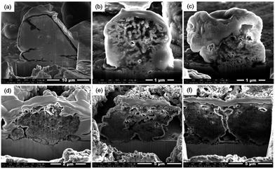 | ||
| Fig. 3 Internal microstructure of Sn islands after (a) 1st Li+ insertion, (b) after 1st Li+ extraction, (c) after 5th cycle, (d) after 10th cycle, (e) after 20th cycle, and (f) after 50th cycle. | ||
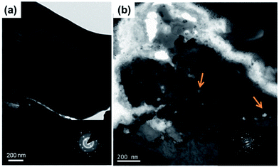 | ||
| Fig. 4 Transmission Electron Microscopy (TEM) images of Sn islands (a) before and (b) after 1st cycle. | ||
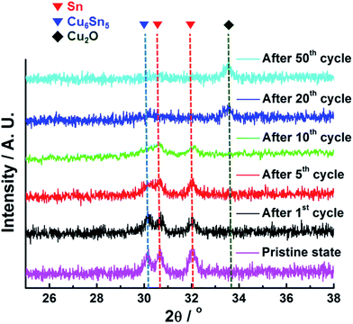
The variations in the crystallographic characteristics of the Sn anode with cycling were verified by ex situ XRD analyses, as can be seen in Fig. 5. The Sn anode was comprised of the two different phases including polycrystalline Sn and Cu6Sn5 in the pristine state (Fig. 1c), but the intensities of the XRD characteristic peaks for both Sn and Cu6Sn5 phases in the Sn anode were gradually reduced with the following cycles, indicative of the phase transformation of polycrystalline Sn into amorphous state after 20th cycle. Small amount of Cu2O phase also could be formed from the Cu6Sn5 with low crystallinity.20 The selected area electron diffraction (SAED) patterns of a single Sn island (insets in Fig. 4) also showed the formation of partial amorphous Sn phase after 1st cycle. Actually, before cycling, the typical spot patterns of single-crystalline Sn phase were observed. At the same time, the XRD peak position of the Sn phase shifted to the right probably due to the stress induced by the amorphization of Sn accompanied by void generation. However, considering that the amorphization proceeded over 20 cycles and the irreversible volume expansion of the Sn anode rapidly proceeded even after 1st cycle, it could be concluded that the irreversible volume expansion of the Sn anode was primarily associated with the void formation in the Sn islands.
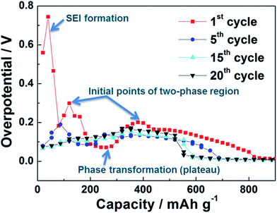
Fig. 6 represents the voltage polarization (ΔV) of the Sn anode as a function of state of charge (SOC) with cycling. The voltage polarization, indicative of overpotential, was calculated from the differences between open circuit voltage (OCV) and closed circuit voltage (CCV) recorded from the galvanostatic intermittent titration technique (GITT) profiles of the Sn anode (Fig. S1†). Here, the electrode resistance of the Sn anode could be estimated from the voltage polarization because it is correlated with the polarization (ΔV) by Ohm's law (R = ΔV/I).21 At the initial stage of Li alloying during 1st cycle, the voltage polarization of the Sn anode was abruptly raised induced by the formation of SEI layers on the surface of the Sn anode and then it reached a constant voltage polarization region (∼0.1 V vs. Li+/Li) due to the phase transformation of polycrystalline Sn into amorphous state.22,23 This corresponds to the ex situ XRD patterns of Sn anode with cycling (Fig. 5). At the middle stage of Li alloying, the voltage polarization of the Sn anode decreased to ∼0 V. After 1st cycle, irrespective of cycle number, all the Sn anodes showed similar polarization behavior including a minor voltage polarization plateau at the initial stage of Li alloying during cycling. However, it is significant that the reversible capacity of the Sn anode decreased with an increase in voltage polarization (i.e. electrode resistance). Thus, the poor cycling performance of the Sn anode was possibly due to its reduced conductivity by the formation of widespread voids and the following dead volume inside the Sn islands with cycling, which could expand the volume of the Sn anode irreversibly as well.
Conclusions
In summary, the main causes of irreversible volume expansion of Sn were investigated in the present study. We succeeded in preparing an island-type Sn anode by electrodeposition. The changes in the inner and outer morphology of Sn islands with cycling were observed by SEM-FIB and TEM analyses. We found from the cross-sectional SEM images of the Sn islands that a variety of nano-voids were formed inside the Sn islands and then they were developed to generate severe clacks within 50 cycles. At the same time, the external microstructure of the Sn islands was transformed from angulated solid to walnut-like in shape accompanied by an agglomeration of neighboring Sn islands. Finally, we suggest that the formation and development of widespread nano-voids within the Sn islands resulted in the continuous volume expansion of the Sn anode during cycling, which causes the poor cycling performance of the Sn anode. These findings pave a way for helping the development of Sn-based anode technology as anode materials for lithium rechargeable batteries.Acknowledgements
This work was supported by the BK21 program funded by Korea Ministry of Knowledge Economy and the Technology Innovation Program (10063288) funded By the Ministry of Trade, Industry & Energy (MOTIE, Korea).Notes and references
- I. A. Courtney and J. R. Dahn, J. Electrochem. Soc., 1997, 144, 2045–2052 CrossRef CAS.
- Y. Idota, K. Kubota, A. Matsufuji, Y. Maekawa and T. Miyasaka, Science, 1997, 276, 1395–1397 CrossRef CAS.
- M. Winter and J. O. Besenhard, Electrochim. Acta, 1999, 45, 31–50 CrossRef CAS.
- J. Yang, Y. Takeda, N. Imanishi and O. Yamamoto, J. Electrochem. Soc., 1999, 146, 4009–4013 CrossRef CAS.
- M. Wachtler, J. O. Besenhard and M. Winter, J. Power Sources, 2001, 94, 189–193 CrossRef CAS.
- S. Sharma, L. Fransson, E. Sjostedt, L. Nordstrom, B. Johansson and K. Edstrom, J. Electrochem. Soc., 2003, 150, A330–A334 CrossRef CAS.
- O. Mao, R. A. Dunlap and J. R. Dahn, J. Electrochem. Soc., 1999, 146, 405–413 CrossRef CAS.
- J. Hassoun, S. Panero, P. Simon, P. L. Taberna and B. Scrosati, Adv. Mater., 2007, 19, 1632–1635 CrossRef CAS.
- F. Xin, X. Wang, J. Bai, W. Wen, H. Tian, C. Wang and W. Han, J. Mater. Chem. A, 2015, 3, 7170–7178 CAS.
- J. O. Besenhard, J. Yang and M. Winter, J. Power Sources, 1997, 68, 87–90 CrossRef CAS.
- L. Y. Beaulieu, S. D. Beattie, T. D. Hatchard and J. R. Dahn, J. Electrochem. Soc., 2003, 150, A419–A424 CrossRef CAS.
- S. C. Chao, Y. C. Yen, Y. F. Song, Y. M. Chen, H. C. Wu and N. L. Wu, Electrochem. Commun., 2010, 12, 234–237 CrossRef CAS.
- H. S. Im, Y. J. Cho, Y. R. Lim, C. S. Jung, D. M. Jang, J. H. Park, F. Shojaei and H. S. Kang, ACS Nano, 2013, 7, 11103–11111 CrossRef CAS PubMed.
- Q. Li, P. Wang, Q. Feng, M. Mao, J. Liu, S. X. Mao and H. Wang, Chem. Mater., 2014, 26, 4102–4108 CrossRef CAS.
- M. T. Janish, D. T. Mackay, Y. Liu, K. L. Jungjohann, C. B. Carter and M. G. Norton, J. Mater. Sci., 2016, 51, 589–602 CrossRef CAS.
- D. H. Nam, R. H. Kim, D. W. Han and H. S. Kwon, Electrochim. Acta, 2012, 66, 126–132 CrossRef CAS.
- R. Z. Hu, M. Q. Zeng and M. Zhu, Electrochim. Acta, 2009, 54, 2843–2850 CrossRef CAS.
- I. T. Lucas, E. Pollak and R. Kostecki, Electrochem. Commun., 2009, 11, 2157–2160 CrossRef CAS.
- S. D. Beattie, T. Hatchard, A. Bonakdarpour, K. C. Hewitt and J. R. Dahn, J. Electrochem. Soc., 2003, 150, A701–A705 CrossRef CAS.
- K.-K. Wang, D. Gan and K.-C. Hsieh, Thin Solid Films, 2010, 519, 1380–1386 CrossRef CAS.
- Y. M. Kang, S. M. Lee, S. J. Kim, G. J. Jeong, M. S. Sung, W. U. Choi and S.-S. Kim, Electrochem. Commun., 2007, 9, 959–964 CrossRef CAS.
- C. Wang, I. Kakwan, A. J. Appleby and F. E. Little, J. Electroanal. Chem., 2000, 489, 55–67 CrossRef CAS.
- C. Wang, A. J. Appleby and F. E. Little, Solid State Ionics, 2002, 147, 13–22 CrossRef CAS.
Footnote |
| † Electronic supplementary information (ESI) available: Galvanostatic intermittent titration technique (GITT) profiles of Sn islands as a function of state of charge (SOC) with cycling. See DOI: 10.1039/c7ra04959e |
| This journal is © The Royal Society of Chemistry 2017 |

