 Open Access Article
Creative Commons Attribution 3.0 Unported Licence
Oxidative desulfurization of model oil in an organic biphasic system catalysed by Fe3O4@SiO2–ionic liquid
Abdolhamid Alizadeh *ab,
Mitra Fakharia,
Mohammad Mehdi Khodeaia,
Gisya Abdia and
Jhaleh Amirianc
aDepartment of Organic Chemistry, Faculty of Chemistry, Razi University, Kermanshah, 6714967346 Iran. E-mail: ahalizadeh2@hotmail.com; ahalizadeh2@razi.ac.ir; Fax: +98 833 427 4559; Tel: +98 833 427 4559
bNanoscience & Nanotechnology Research Center (NNRC), Razi University, Kermanshah, Iran
cDepartment of Regenerative Medicine, College of Medicine, Soonchunhyang University, 366-1, Sangyong-dong, Cheonan-City, Republic of Korea
First published on 11th July 2017
Abstract
Lewis or Brønsted acidic methylimidazolium ionic liquid-functionalized Fe3O4@SiO2 nanoparticles were fabricated and applied as an efficient magnetic heterogeneous catalyst for dibenzothiophene (DBT) oxidation in a biphasic system using H2O2 as the oxidant. The structures of catalysts were characterized by SEM, TEM, XRD, TGA, FT-IR, VSM and EDX techniques. The magnetic catalysts showed high catalytic performance in the oxidation of DBT in an n-hexane/acetonitrile biphasic system using H2O2, and high conversions were obtained. The effects of contact time, temperature, amount of H2O2 and amount of catalyst on the DBT oxidative removal efficiency were investigated. The contact time of 60 min, 0.1 g catalyst, and 4 mL H2O2 at 313 K were found as optimal experimental conditions for an improved DBT oxidative removal process. The sulfur level could be lowered from 100 ppm to less than 7, 5, and 2 ppm under optimal conditions for Fe3O4@SiO2–Mim-BF4, Fe3O4@SiO2–Mim-HSO4, and Fe3O4@SiO2–Mim–FeCl4, respectively. These nanomagnetic heterogeneous catalysts could be easily separated from the reaction mixture by applying an external magnetic field and recycled several times.
1. Introduction
Emission of SOx from the combustion of sulfur compounds in gasoline and diesel oil is one of the issues of concern in the environmental field. Hence, sulfur removal from fuel oils is a crucial challenge from an environmental point. To eliminate sulfur-containing compounds, various processes, have been employed. Generally, the processes include catalytic hydrodesulfurization,1 adsorption,2,3 extraction,4,5 bioprocesses,6,7 and oxidation processes.8–12In industry, the removal of sulfur compounds is carried out by the hydrodesulfurization (HDS) method, which requires harsh condition such as high temperatures and high pressures of hydrogen gas to produce light oil having low levels of sulfur compounds. Thus according to this point oxidative desulfurization (ODS) is taken into consideration owing to favorable operating conditions.
Generally, ODS processes are achieved through oxidation of sulfur compounds to sulfoxides and sulfones followed by a separation process using appropriate extractants or adsorbents.13–15 According to the literature, various oxidative desulfurization systems have been developed16 such as a series of heteropolyacid catalysts,17 ionic liquids systems, acetic acid catalyst,18,19 the amphiphilic phosphotungstic acid catalyst,20 porous glass supported with titanium silicate particles,21 and ultrasound-assisted oxidative desulfurization processes.22
Recently, due to their superior properties including good dissolving ability, nonvolatility, and wide liquid temperature range, ionic liquids (ILs) have become an active area of research. They have been employed as solvents for synthesis and catalysis,23 in electrochemistry,24 extractive25 and oxidative desulfurization.26 In the field of desulfurization in some cases, ionic liquids act as both catalyst and extractant, simultaneously. Some of these ILs are reported as catalysts and extractant for extractive-catalytic-oxidative-desulfurization (ECODS), including N-methyl-2-pyrrolidone-based ionic liquids,27 dialkylpyridinium tetrachloroferrates [Cn3MPy] FeCl4 (n = 4, 6, 8),28 [C4Mim]Cl/MCl2 (M = Zn, Fe, Cu, Mg, Sn, Co),29 [Hnmp]BF4,30 [BMim]HSO4,31 [BMim][HSO4], and [C4Py][HSO4].32 These biphasic systems exhibit some disadvantages, such as high cost, large usage amount of IL, difficult separation and recontamination of oils from the dissolution of traces of catalysts. To overcome these limitations, supported ILs on the various materials as heterogeneous catalysts have been introduced because they not only decrease the cost and the usage amount of ILs but also facilitate separation and recycling of the catalyst. Various kinds of nanomaterials as supports to fix of ionic liquids have been applied such as SiO2, Al2O3 and TiO2 nanoparticles,33 a series of polymer-based materials,5 mesoporous materials,34,35 metal–organic frameworks,36 and graphene-based materials.37 Also, magnetic Fe3O4 nanoparticles have been used as support for ionic liquids. Ionic liquid modified magnetic nanoparticles have been used as catalyst for chemical synthesis,38–40 oxidative desulfurization11,41,42 and adsorbent.43,44
Besides, magnetic catalysts in recent years have been faced with a lot of attention. Meanwhile, magnetic ionic liquids45,46 are applied as extractants and catalysts for desulfurization of model oils.
In this research, for the achievement of magnetically separable catalyst with high catalytic performance, we planned to fabricate and use modified magnetic nanoparticles by Lewis or Brønsted acidic ionic liquids as catalysts for oxidation of dibenzothiophene (DBT) by H2O2 in a biphasic (n-hexane/acetonitrile) system.
2. Experimental
2.1 Materials
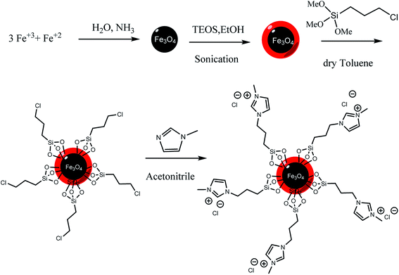
Ferric chloride hexahydrate (FeCl3·6H2O), ferrous chloride tetrahydrate (FeCl2·4H2O), sodium tetrafluoroborate (NaBF4), sodium hydrogen sulfate (NaHSO4), iron(III) chloride (FeCl3), tetraethylorthosilicate (TEOS), (3-chloropropyl)tri-methoxysilane (CPTS), 1-methyl imidazole were purchased from Sigma-Aldrich. Ammonia, acetonitrile, n-hexane, toluene, and ethanol were procured from Merck. All other reagents used in this study were analytical grade and distilled or double distilled water was used in the preparation of all solutions.2.2 Analysis instruments
X-ray diffraction (XRD) spectra were recorded on D/MAX-250, Rigaku, Tokyo, Japan using 40 kV with Cu Kα irradiation (λ = 1.541 Å). Fourier transform infrared (Bruker FTIR) spectra were recorded in KBr pellets in the range of 400–4000 cm−1. Scanning electron microscopy (SEM) images of the product were taken using a JSM-6701F microscope (JEOL, Japan) equipped for EDS. Transmission electron microscopy (TEM) was performed on JEOL JEM-1010n. The magnetic measurements were carried out in a vibrating sample magnetometer (VSM, BHV-55, Riken, Japan) at room temperature. Thermogravimetric analysis (TGA) was carried out using a Q5000IR (TA instruments) under nitrogen flow (100 mL min−1) with ramp rate of 10 °C min−1. UV-visible spectra were recorded by Perkin Elmer Lambda 25 spectrometer.2.3 Methods
3. Results and discussion
3.1 Characterization of catalyst
The morphology of Fe3O4@SiO2–methylimidazolium chloride nanoparticles was studied by transmission electron microscopy (SEM) shown in Fig. 1a. The TEM observation indicates that magnetite nanoparticles are monodispersed and have an average diameter ranging about 10–15 nm (Fig. 1b). | ||
| Fig. 1 (a) SEM image of Fe3O4@SiO2–methylimidazolium chloride and (b) TEM image Fe3O4@SiO2–methylimidazolium chloride. | ||
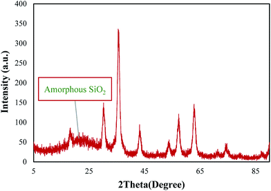
The crystalline structure of Fe3O4@SiO2–methylimidazolium chloride nanoparticles was identified with XRD technique (Fig. 2). For silica and ionic liquid coated Fe3O4, diffraction peaks with 2θ at 30.4°, 35.6°, 43.3°, 53.7°, 57.3°, and 62.8°, indicative of a cubic spinel structure of the magnetite were observed which conforms well to the reported value, implying the formation of a Fe3O4 phase.50 The presence of a broad peak at 20–28° is in good agreement with the amorphous structure of silica layer.47
TGA analyses of the nanoparticles were also used to determine the percent of organic functional groups chemisorbed onto the surface of Fe3O4@SiO2–methylimidazolium chloride. Fig. 3 represents the TGA of as-prepared Fe3O4@SiO2–methylimidazolium chloride. The weight loss at temperatures below 100 °C can be attributed to the water desorption from the surface of silica layer.51 Complete loss of all the covalently attached organic structure is seen in the 200–600 °C temperature range leaving SiO2, and the organic fraction corresponds to 8.5% weight of the ionic liquid modified silica.52 These results prove that the attachment of imidazolium moiety onto the surface of the Fe3O4@SiO2 nanoparticle.
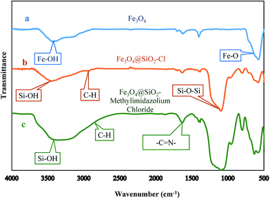
The FTIR spectra (Fig. 4) certified the structure of Fe3O4@SiO2–Fe3O4@SiO2–methylimidazolium chloride. The observed signal at 579 cm−1 is ascribed to the Fe–O bond vibration. In the case of Fe3O4@SiO2–Cl nanoparticles (curve b), the sharp band at 1090 cm−1 is corresponding to Si–O–Si antisymmetric stretching vibration, being indicative of the existence of a SiO2 layer around the Fe3O4 nanoparticles.53 The peaks in b and c at 1633 cm−1 and 2930 cm−1 were due to the –C![[double bond, length as m-dash]](https://www.rsc.org/images/entities/char_e001.gif) N–, and C–H groups, respectively.43 Furthermore, the broad absorption in the region of 3445 cm−1 is due to the Si–OH groups on the surface of the silica. These results demonstrated the successful bonding of imidazolium ring to the magnetic nanoparticles by covalent bonds.
N–, and C–H groups, respectively.43 Furthermore, the broad absorption in the region of 3445 cm−1 is due to the Si–OH groups on the surface of the silica. These results demonstrated the successful bonding of imidazolium ring to the magnetic nanoparticles by covalent bonds.
The magnetic property of ionic liquid supported magnetic nanoparticles was characterized by a vibrating sample magnetometer (VSM) and Fig. 5 shows the typical room temperature magnetization curve of Fe3O4 and Fe3O4@SiO2–methylimidazolium chloride nanoparticles. The saturation magnetization (Ms) of the Fe3O4@SiO2–methylimidazolium chloride is 43 emu g−1 (Fig. 5), indicating the high magnetic property. As seen in Fig. 5 the Ms of Fe3O4 is 59 emu g−1. The lower saturation magnetization of the Fe3O4@SiO2–methylimidazolium chloride compared to the Fe3O4 could be ascribed to the attached organic layer to the surface of Fe3O4 nanoparticles. The left inset of Fig. 5 shows that Fe3O4@SiO2–methylimidazolium chloride is attracted by an external magnet, and the clear biphasic system can be easily removed by pipet or decanting.
3.2 Anion exchange process
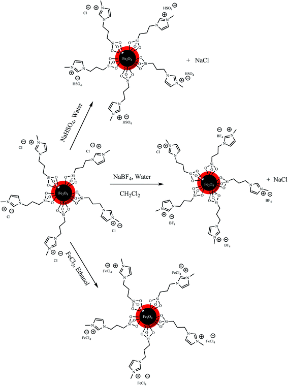 | ||
| Scheme 2 Schematic illustration of Fe3O4@SiO2–methylimidazolium chloride nanoparticles anion exchange. | ||
| Element | Weight% | ||
|---|---|---|---|
| Fe3O4@SiO2–Mim-BF4 | Fe3O4@SiO2–Mim-HSO4 | Fe3O4@SiO2–Mim–FeCl4 | |
| Fe | 34.87 | 32.50 | 43.95 |
| O | 34.90 | 33.97 | 31.47 |
| Si | 17.01 | 18.30 | 12.44 |
| C | 7.01 | 6.98 | 7.08 |
| N | 1.83 | 2.01 | 2.02 |
| Cl | — | 0.40 | 3.04 |
| F | 0.38 | — | — |
| B | 0.08 | — | — |
| S | — | 0.19 | — |
| Au | 3.92 | 5.64 | — |
| Total | 100 | 100 | 100 |
3.3 Oxidation procedure
Model oils were prepared by dissolving DBT in n-hexane give solutions with a sulfur content of 100 ppm. The extraction and catalytic oxidative desulfurization experiments were performed in a stirred 100 mL round-bottom flask, to which catalyst and model oil (25 mL) and acetonitrile (25 mL) as extractant phase were added in turn. Until the extractive equilibrium was reached after 10 min, a certain amount of 30 wt% H2O2 was injected to the flask. Then the mixture was stirred vigorously at 40 °C for 60 min. The concentrations of DBT were analyzed using a UV spectrophotometer. The phase fractional was taken from n-hexane phase for DBT analysis. In during the reaction time in intervals 10 min the model oil was separated by decantation after collection of the catalyst by external magnetic field then the sulfur concentration in oil phase calculated via UV-VIS spectrophotometer. The absorption at 283 nm was used to monitor the DBT concentration. Fig. 7 shows the variations of the UV-vis spectra of the DBT in n-hexane at time intervals 10, 20, 30, 40, 50, 60 min. The decrease of intensity in these UV-vis bands, indicates that the concentration of DBT in n-hexane decreases during the reaction time. Dibenzothiophene sulfone formation in acetonitrile phase was monitored by thin-layer chromatography (TLC). Sulfone formation was confirmed by the melting point of the obtained product (229–232 °C). | ||
| Fig. 7 The variations of the UV-vis spectra of the DBT at time intervals: 10, 20, 30, 40, 50, 60 minutes. | ||
3.4 Control experiments
To evaluate the performance of ionic liquid-modified silica-coated magnetic nanoparticles as catalysts in the oxidation of DBT from a biphasic system, we set four parallel control experiments to make a comparison on the performance of Fe3O4@SiO2, Fe3O4@SiO2–Cl, Fe3O4@SiO2–imidazolium chloride and Fe3O4@SiO2–Mim–FeCl4 as catalysts. The obtained data was shown in Table 2. As can be seen in Table 2 conversion of dibenzothiophene to dibenzothiophene sulfone was not observed. These observations were contributed to this fact that on the surfaces of Fe3O4@SiO2, Fe3O4@SiO2–Cl and Fe3O4@SiO2–methylimidazolium chloride nanoparticles does not exist necessary sites for activation of H2O2.| Catalyst | Dispersity in acetonitrile | Conversion% |
|---|---|---|
| a Experimental conditions: amount of catalyst: 0.1 g, amount of H2O2: 4 mL, time: 60 minutes, temperature: 313 K. | ||
| Fe3O4@SiO2 | ✓ | 0 |
| Fe3O4@SiO2–Cl | ✓ | 0 |
| Fe3O4@SiO2–methylimidazolium chloride | ✓✓✓ | 0 |
| Fe3O4@SiO2–Mim–FeCl4 | ✓✓✓ | 98 |
The presence of the ionic liquid moieties on the surface of magnetic nanoparticles leading to high polarity of the catalyst surface and the polar catalyst could be easily dispersed in acetonitrile phase. First DBT influenced from nonpolar n-hexane phase to the polar acetonitrile phase. On the other hand, H2O2 as an oxidant could be easily adsorbed to the polar surface of the catalyst and then the oxidation process continues.
3.5 The proposed process and mechanism of DBT oxidation by Fe3O4@SiO2–Mim-BF4
The proposed mechanism of DBT oxidation by Fe3O4@SiO2–Mim-BF4 nanocatalyst was shown in Scheme 4. As can be seen, the efficiency of the oxidation can be explained by the interaction between the Fe3O4@SiO2–Mim-BF4 and H2O2. The boron of anionic moiety of the catalyst can attract H2O2 and increases the electrophilic ability of a peroxy oxygen atom of H2O2 and the electrophilic oxygen is attacked by sulfur of DBT. After eliminating one water molecule, dibenzothiophene sulfoxide is produced. In continuous by cooperation of catalyst and oxidant, oxidation process continues and dibenzothiophene sulfone is produced.3.6 The suggested process and mechanism of DBT oxidation by Fe3O4@SiO2–Mim-HSO4
According to the last researches31,55,56 about oxidation of sulfides by Brønsted acidic catalysts, the proposed mechanism for the oxidation of sulfide to the corresponding sulfoxide is shown in Scheme 5. The efficiency of the oxidation can be explained by the interaction between the Fe3O4@SiO2–Mim-HSO4 and H2O2. The OH moiety of the Fe3O4@SiO2–Mim-HSO4 forms a strong hydrogen bond with H2O2 and increases the electrophilic ability of a peroxy oxygen atom of H2O2, and at the same time assists the leaving group (H2O) in departing from the reaction intermediate.3.7 The suggested process and mechanism of DBT oxidation by Fe3O4@SiO2–Mim–FeCl4
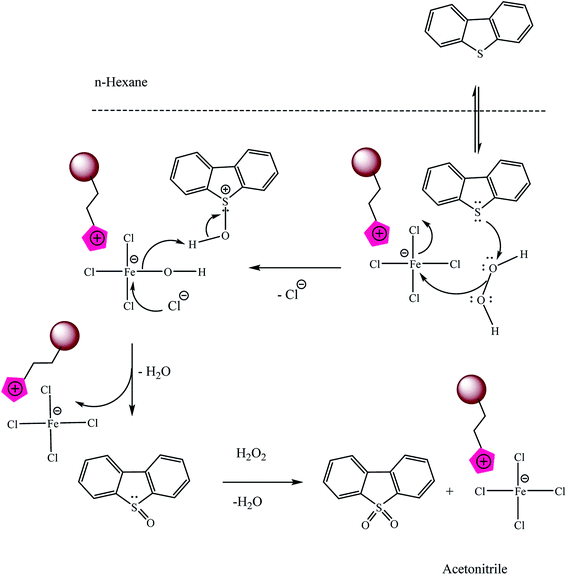
The Fe3+ in Fe3O4@SiO2–Mim–FeCl4 and H2O2 formed a Fenton-like reagent because [FeCl4]− can dissociate Fe3+.27,28,57,58 H2O2 can be decomposed into active hydroxyl radicals (HO˙) that are strong oxidizing agents for DBT (eqn (1)–(3)).| Fe3+ + H2O2 → [Fe(HO2)]2+ + H+ | (1) |
 | (2) |
| Fe2+ + H2O2 → Fe3+ + HO˙ + OH− | (3) |
Another possible mechanism was illustrated in the Scheme 6:
In the following sections influence of some effective factors on desulfurization of model oil including the amount of catalyst, the amount of H2O2, and time were examined. The results were discussed.
3.8 The amount of H2O2 effect on DBT oxidative removal
The oxidation of DBT under various H2O2 volume was conducted at 40 °C to study the effect of the dosage of oxidant on the oxidative properties. As shown in Fig. 8 by increasing the amount of H2O2, DBT oxidation growth. | ||
| Fig. 8 The effect of the amount of H2O2 on the conversation of DBT. Experimental conditions: amount of catalyst: 0.1 g, time: 60 minutes, temperature: 313 K. | ||
3.9 Effect of the amount of the catalyst on DBT removal
The catalysts amount effect on desulfurization is shown in Fig. 9. The results indicated that the amount of the catalyst had a vital effect on the oxidation of DBT. For tree type of catalyst by increasing the amount of catalyst from 0.05 g to 0.1 g the percent of DBT oxidation increase. Obviously, the excessive catalyst was not necessary and economical in the process. Thus, 0.1 g was chosen as the most suitable quantity in this study. | ||
| Fig. 9 The effect of the amount of catalyst on the conversation of DBT. Experimental conditions: amount of H2O2: 4 mL, time: 60 minutes, temperature: 313 K. | ||
3.10 Effect of reaction time on oxidative removal of DBT
The DBT oxidation versus reaction time was determined according to the following equation (eqn (4)), where C0 is the concentration at time zero and Ct is the DBT concentration at the time.
 | (4) |
As indicated in the graph conversion of DBT increased over time (Fig. 10).
 | ||
| Fig. 10 The effect of the time on the conversation of DBT. Experimental conditions: amount of catalyst: 0.1 g, amount of H2O2: 4 mL, temperature: 313 K. | ||
The oxidative desulfurization efficiency were increased with increasing temperature. Sulfur removal reached to near 100% at 328 K in 60 min. Removal of DBT can be reached at 298 and 313 K in 60 min to 70.20 and 98% respectively. Therefore, 40 °C was chosen in the present study because of the concentration of hydrogen peroxide decreases due to nonproductive decomposition at high temperature (Fig. 11).13
 | ||
| Fig. 11 The effect of temperature on the conversation of DBT. Experimental conditions: amount of catalyst: 0.1 g, amount of H2O2: 4 mL, time: 60 minutes. | ||
3.11 Recycling of the catalysts
To further investigation the stability of catalysts, a series of catalyst recycle and reuse experiments for the DBT oxidation were conducted. Then a new reaction setup was accomplished with the fresh solvent and reactants under the same conditions. These catalysts can be easily recycled for further use because of its magnetism. Over four times of the recycle experiments conversion percentage has not changed much (Fig. 12). The high stability and excellent reusability of the catalyst can be contributed to the strong electrostatic interaction between the imidazolium ring and anionic moiety.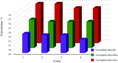 | ||
| Fig. 12 Recycling of catalysts. Experimental conditions: amount of catalyst: 0.1 g, amount of H2O2: 4 mL, time: 60 minutes, temperature: 313 K. | ||
4. Conclusion
The main focus of the present research was concerned with achieving the efficient and feasible protocol for oxidative removal of DBT. Accordingly, we synthesized a series of Fe3O4-supported imidazolium-based Lewis or Brønsted acidic ionic liquids and applied as polar and nanomagnetic heterogeneous catalyst for oxidative desulfurization of dibenzothiophene from n-hexane as model oil phase in n-hexane/acetonitrile biphasic system. The order of catalysts performance was Fe3O4@SiO2–Mim–FeCl4 > Fe3O4@SiO2–Mim-HSO4 > Fe3O4@SiO2–Mim-BF4, the reason for this was that interaction between [FeCl4]− moiety and oxygen of H2O2 was stronger than the others. Finally, regeneration and subsequent recycling of Lewis or Brønsted acidic methylimidazolium ionic liquid-functionalized Fe3O4@SiO2 nanoparticles have been investigated. The results showed that these catalysts could be used as promising catalysts for the oxidative desulfurization of future industrial application due to their higher desulfurization rates and easy separation by an external magnetic field.Acknowledgements
The authors are grateful to Razi University for their financial support for the accomplishment of the work and providing necessary facilities. M. Fakhari is also thankful to the Iran Nanotechnology Initiative Council (INIC) for their partial support on this project.References
- X. Ma, K. Sakanishi and I. Mochida, Ind. Eng. Chem. Res., 1994, 33, 218–222 CrossRef CAS.
- A. Srivastav and V. C. Srivastava, J. Hazard. Mater., 2009, 170, 1133–1140 CrossRef CAS PubMed.
- X. Ma, L. Sun and C. Song, Catal. Today, 2002, 77, 107–116 CrossRef CAS.
- S. Zhang, Q. Zhang and Z. C. Zhang, Ind. Eng. Chem. Res., 2004, 43, 614–622 CrossRef CAS.
- X. Wang, H. Wan, M. Han, L. Gao and G. Guan, Ind. Eng. Chem. Res., 2012, 51, 3418–3424 CrossRef CAS.
- D. J. Monticello, Curr. Opin. Biotechnol., 2000, 11, 540–546 CrossRef CAS PubMed.
- B. H. Kim, H. Y. Kim, T. S. Kim and D. H. Park, Fuel Process. Technol., 1995, 43, 87–94 CrossRef CAS.
- X.-M. Yan, P. Mei, L. Xiong, L. Gao, Q. Yang and L. Gong, Catal. Sci. Technol., 2013, 3, 1985–1992 CAS.
- J. Gao, W. Ma, L. Yuan, Y. Dai and C. Li, Appl. Catal., A, 2013, 467, 187–195 CrossRef CAS.
- J. Zhang, A. Wang, Y. Wang, H. Wang and J. Gui, Chem. Eng. J., 2014, 245, 65–70 CrossRef CAS.
- X. Cui, D. Yao, H. Li, J. Yang and D. Hu, J. Hazard. Mater., 2012, 205, 17–23 CrossRef PubMed.
- W. Jiang, W. Zhu, Y. Chang, Y. Chao, S. Yin, H. Liu, F. Zhu and H. Li, Chem. Eng. J., 2014, 250, 48–54 CrossRef CAS.
- H. Lü, W. Ren, H. Wang, Y. Wang, W. Chen and Z. Suo, Appl. Catal., A, 2013, 453, 376–382 CrossRef.
- W. Zhu, W. Huang, H. Li, M. Zhang, W. Jiang, G. Chen and C. Han, Fuel Process. Technol., 2011, 92, 1842–1848 CrossRef CAS.
- K. Yazu, Y. Yamamoto, T. Furuya, K. Miki and K. Ukegawa, Energy Fuels, 2001, 15, 1535–1536 CrossRef CAS.
- A. A. Gulam Gaush Zeelani, A. Dhakad, G. Gupta and S. L. Pal, Int. J. Eng. Res. Tech., 2016, 3, 331–336 Search PubMed.
- L. Tang, G. Luo, M. Zhu, L. Kang and B. Dai, J. Ind. Eng. Chem., 2013, 19, 620–626 CrossRef CAS.
- W.-H. Lo, H.-Y. Yang and G.-T. Wei, Green Chem., 2003, 5, 639–642 RSC.
- L. Chen, S. Guo and D. Zhao, Chin. J. Chem. Eng., 2007, 15, 520–523 CrossRef CAS.
- G.-N. Yun and Y.-K. Lee, Fuel Process. Technol., 2013, 114, 1–5 CrossRef CAS.
- C. Shen, Y. J. Wang, J. H. Xu and G. S. Luo, Chem. Eng. J., 2015, 259, 552–561 CrossRef CAS.
- F. A. Duarte, P. d. A. Mello, C. A. Bizzi, M. A. G. Nunes, E. M. Moreira, M. S. Alencar, H. N. Motta, V. L. Dressler and É. M. M. Flores, Fuel, 2011, 90, 2158–2164 CrossRef CAS.
- T. Welton, Chem. Rev., 1999, 99, 2071–2084 CrossRef CAS PubMed.
- M. Armand, F. Endres, D. R. MacFarlane, H. Ohno and B. Scrosati, Nat. Mater., 2009, 8, 621–629 CrossRef CAS PubMed.
- R. Abro, A. A. Abdeltawab, S. S. Al-Deyab, G. Yu, A. B. Qazi, S. Gao and X. Chen, RSC Adv., 2014, 4, 35302–35317 RSC.
- A. W. Bhutto, R. Abro, S. Gao, T. Abbas, X. Chen and G. Yu, J. Taiwan Inst. Chem. Eng., 2016, 62, 84–97 CrossRef CAS.
- F.-t. Li, B. Wu, R.-h. Liu, X.-j. Wang, L.-j. Chen and D.-s. Zhao, Chem. Eng. J., 2015, 274, 192–199 CrossRef CAS.
- Y. Nie, Y. Dong, L. Bai, H. Dong and X. Zhang, Fuel, 2013, 103, 997–1002 CrossRef CAS.
- X. Chen, D. Song, C. Asumana and G. Yu, J. Mol. Catal. A: Chem., 2012, 359, 8–13 CrossRef CAS.
- J. Wang, D. Zhao and K. Li, Energy Fuels, 2009, 23, 3831–3834 CrossRef CAS.
- W. Zhang, K. Xu, Q. Zhang, D. Liu, S. Wu, F. Verpoort and X.-M. Song, Ind. Eng. Chem. Res., 2010, 49, 11760–11763 CrossRef CAS.
- H. Gao, C. Guo, J. Xing, J. Zhao and H. Liu, Green Chem., 2010, 12, 1220–1224 RSC.
- J. Zhang, A. Wang, X. Li and X. Ma, J. Catal., 2011, 279, 269–275 CrossRef CAS.
- J. Xiong, W. Zhu, H. Li, Y. Xu, W. Jiang, S. Xun, H. Liu and Z. Zhao, AIChE J., 2013, 59, 4696–4704 CrossRef CAS.
- W. Ding, W. Zhu, J. Xiong, L. Yang, A. Wei, M. Zhang and H. Li, Chem. Eng. J., 2015, 266, 213–221 CrossRef CAS.
- N. A. Khan, Z. Hasan and S. H. Jhung, Chem.–Eur. J., 2014, 20, 376–380 CrossRef CAS PubMed.
- W. Zhu, B. Dai, P. Wu, Y. Chao, J. Xiong, S. Xun, H. Li and H. Li, ACS Sustainable Chem. Eng., 2015, 3, 186–194 CrossRef CAS.
- Z. Wu, Z. Li, G. Wu, L. Wang, S. Lu, L. Wang, H. Wan and G. Guan, Ind. Eng. Chem. Res., 2014, 53, 3040–3046 CrossRef CAS.
- M. Esmaeilpour, J. Javidi and M. Zandi, Mater. Res. Bull., 2014, 55, 78–87 CrossRef CAS.
- P.-H. Li, B.-L. Li, H.-C. Hu, X.-N. Zhao and Z.-H. Zhang, Catal. Commun., 2014, 46, 118–122 CrossRef CAS.
- Z. Zhang, F. Zhang, Q. Zhu, W. Zhao, B. Ma and Y. Ding, J. Colloid Interface Sci., 2011, 360, 189–194 CrossRef CAS PubMed.
- Y. Chen, F. Zhang, Y. Fang, X. Zhu, W. Zhen, R. Wang and J. Ma, Catal. Commun., 2013, 38, 54–58 CrossRef CAS.
- M. Davudabadi Farahani and F. Shemirani, Microchim. Acta, 2012, 179, 219–226 CrossRef CAS.
- X. Liu, X. Lu, Y. Huang, C. Liu and S. Zhao, Talanta, 2014, 119, 341–347 CrossRef CAS PubMed.
- E. Santos, J. Albo and A. Irabien, RSC Adv., 2014, 4, 40008–40018 RSC.
- W. Zhu, P. Wu, L. Yang, Y. Chang, Y. Chao, H. Li, Y. Jiang, W. Jiang and S. Xun, Chem. Eng. J., 2013, 229, 250–256 CrossRef CAS.
- D. Yang, J. Hu and S. Fu, J. Phys. Chem. C, 2009, 113, 7646–7651 CAS.
- W. Stöber, A. Fink and E. Bohn, J. Colloid Interface Sci., 1968, 26, 62–69 CrossRef.
- T. Zeng, L. Yang, R. Hudson, G. Song, A. R. Moores and C.-J. Li, Org. Lett., 2011, 13, 442–445 CrossRef CAS PubMed.
- T. Yang, C. Shen, Z. Li, H. Zhang, C. Xiao, S. Chen, Z. Xu, D. Shi, J. Li and H. Gao, J. Phys. Chem. B, 2005, 109, 23233–23236 CrossRef CAS PubMed.
- Z. Lei, Y. Li and X. Wei, J. Solid State Chem., 2008, 181, 480–486 CrossRef CAS.
- A. S. Amarasekara and O. S. Owereh, Catal. Commun., 2010, 11, 1072–1075 CrossRef CAS.
- M. Yamaura, R. L. Camilo, L. C. Sampaio, M. A. Macêdo, M. Nakamura and H. E. Toma, J. Magn. Magn. Mater., 2004, 279, 210–217 CrossRef CAS.
- X. Creary and E. D. Willis, Org. Synth., 2005, 82, 166–169 CrossRef CAS.
- K. Bahrami, M. M. Khodaei and P. Fattahpour, Catal. Sci. Technol., 2011, 1, 389–393 CAS.
- M. M. Khodaei, K. Bahrami and M. Sheikh Arabi, J. Sulfur Chem., 2010, 31, 83–88 CrossRef CAS.
- J. Zhang, W. Zhu, H. Li, W. Jiang, Y. Jiang, W. Huang and Y. Yan, Green Chem., 2009, 11, 1801–1807 RSC.
- J. Xiong, W. Zhu, H. Li, Y. Xu, W. Jiang, S. Xun, H. Liu and Z. Zhao, AIChE J., 2013, 59, 4696–4704 CrossRef CAS.
| This journal is © The Royal Society of Chemistry 2017 |

