DOI:
10.1039/C7RA04770C
(Paper)
RSC Adv., 2017,
7, 33477-33485
In situ polymerization and characterization of graphite nanoplatelet/poly(ethylene terephthalate) nanocomposites for construction of melt-spun fibers
Received
28th April 2017
, Accepted 19th June 2017
First published on 3rd July 2017
Abstract
A set of novel nanocomposites based on graphite nanoplatelets (GnP) and poly(ethylene terephthalate) (PET) were synthesized using an in situ polymerization approach that were subsequently being spun into fibers on a melt spinning apparatus. The GnP/PET nanocomposites with a filler weight fraction below 2% showed a homogenous fractured surface as a result of good dispersion of GnP in the PET matrix through preliminary dispersant treatment coupled with subsequent melt compounding during the polymerization. Compared to unmodified PET, the GnP/PET nanocomposites were confirmed to improve thermal stabilities and increase crystallization rates which were capable of facilitating the downstream procedure of melt spinning. At a low level of GnP loading, the PET matrix nanocomposite fibers were readily melt-spun without detecting fiber breakage or filament defect and exhibited mechanical properties similar to unmodified PET fiber as the compact interaction was formed between GnP and PET matrix. Particularly, the volume resistivity of the resultant nanocomposite fibers was found to be substantially reduced due to the intrinsic electrical conductivity that the GnP imparts as a filler. Taken together, our work introduces a simple and environmentally friendly method for melt spinning of GnP/PET nanocomposite fibers with great potential for applications in antistatic textile and military industries.
Introduction
Polymer–matrix nanocomposites have recently attracted attention from researchers owing to their unique chemical and physical properties. The fillers that are often utilized for constructing polymeric nanocomposites include exfoliated nanoclays, carbon-based nanofillers, and metal oxide nanoparticles, etc.1–3 Among these carbon-based nanofillers, graphene is a newly-discovered carbon nanosheet featuring a one-atom-thick structure that is composed of sp2-hybridized carbon atoms densely packed in a hexagonal lattice.4 Particularly, it can serve as a block unit to construct other classifications of graphitic carbon, such as zero-dimension (0D) fullerene, 1D carbon nanotube (CNT), and 3D graphite nanoplatelet (GnP), etc. Many studies have reported that graphene nanosheet and CNT improve the mechanical, thermal and electrical properties of the filled polymer matrix.4,5 For instance, polyamide-66 (PA66) incorporated with CNTs increased the tensile strength and Young modulus by 191% and 294%, respectively.6 The electric conductivity of poly(ethylene terephthalate) (PET) is dramatically reduced from 2.0 × 10⁻¹³ S m−1 to 7.4 × 10⁻² S m−1 when graphene nanosheet is introduced as the filler.7 However, the extensive applications of graphene nanosheet and CNT are unfortunately limited by their high price and low production capacity. In recent years, GnP has emerged as an alternative carbon-based nanofiller for polymeric nanocomposites as it displays more versatile properties and economic benefits compared to other fillers.
GnP is a type of carbon generally manufactured with natural flake graphite and composed of small stacks of graphene nanosheets with dimensions in the order of nanometers thick and sub-micrometer to micrometer long/wide. GnP exhibits high thermal stability, superior electric conductivity, long-term chemical stability, and it has rich natural resource with low production cost and industrially scaled manufacture.8–11 Like other members of carbon-based nanofillers, GnP at the rational amount of addition is also capable of reinforcing the correspondent polymer matrix. Polyamide 12 (PA12)/GnP nanocomposites prepared by melt compounding and injection molding was found that GnP acted as nucleating agent for PA12 and significantly altered the physical properties of the polymers.12 A series of form-stable phase change materials (PCMs) have been synthesized in which palmitic acid (PA), polyaniline (PANI) and GnP were applied as solid–liquid PCMs, the results showed that the thermal conductivity of the PCM doped with 7.87 wt% of GnP could attain 1.08 W m−1 K−1, which was 237.5% higher than that of PA/PANI.13 The study reported by Zhang showed that PET/GnP composites prepared through melt blending approach displayed a decrease in electrical resistivity from 3.5 × 10⁻⁸ Ω cm to 2.2 × 10⁻³ Ω cm when GnP loading increased from 8% to 12%.14 Nevertheless, the compressive and flexural strength of the nanocomposites was observed to sharply decrease when the content of graphite was beyond 12%, confirming that only a limited quantity of GnP in the polymer matrix can guarantee the improvements in mechanical properties for their generated nanocomposites.
PET, a semi-crystalline polymer, has been considered to be the first industrialized linear thermoplastic polymer in the world.15,16 The melt-spun PET fiber is also regarded as the most common polyester fiber in textile industry as its low production cost and excellent chemical & physical properties and has widespread applications in many fields, such as costume fabric, package materials, and military device, etc.17,18 It is reported that the highest Young's modulus, tensile strain and toughness of PET fiber prepared under the certain processing condition can reach up to ∼10 GPa, ∼1 GPa, and 200 MJ m−3, respectively. Moreover, PET fiber is extremely ductile which can exhibit the tensile strength at break ranging from 20 to 100%. However, the application of PET fiber is still limited due to its low moisture regain, undesirable dyeing behavior and poor antistatic property, etc.19–21 To increase the antistatic property and further extend the application of PET fiber, many researchers have developed graphene nanosheet or CNT/PET nanocomposite fibers through blending the fillers and PET in double screw extrusion machine and granulating into particles before melt spinning.22–24 However, the production of melt-spun GnP/PET fibers using in situ polymerized nanocomposites has not been explored.
In this work, GnP/PET nanocomposites were synthesized via in situ polymerization of ethylene glycol (EG) and purified terephthalate acid (PTA) in the presence of different concentrations of GnP. To achieve a good dispersion of GnP in the nanocomposites, the effects of dispersants on EG/GnP suspension for the downstream polymerization were investigated. The morphological and thermal properties of GnP/PET nanocomposites with the GnP loading varing from 0.5% to 4% were examined. On the other hand, the fibers were subsequently spun with the polymerized nanocomposites through a double-screw melt spinning machine. The morphologies of surface and cross-section of the GnP/PET nanocomposite fibers were imaged by FE-SEM. To study whether the incorporation of GnP could reinforce the melt-spun fibers just like the function it played in the nanocomposites, the tenacity and elongation at break of the resultant fibers with different drawing ratios were tested in comparison with that of PET fiber. Furthermore, the antistatic property of GnP/PET nanocomposite fibers was evaluated by measuring the volume resistivity of the fibers at certain humidity atmosphere.
Experimental
Materials
Purified terephthalate acid (PTA) was provided by Hengyi Petrochemical Co., Ltd. (Zhejiang, China). Ethylene glycol (EG) and ethylene glycol antimony (Sb2EG3) were supplied by Liaoyang Petrochemical Co., Ltd. (Liaoning, China). GnP was offered by Jinan Shengquan Group Holding Co., Ltd. (Shandong, China), with the average size at 10 to 20 nm in thickness and 1 to 10 μm in length & width (99%). All the chemicals but not mentioned above were purchased from Sinopharm Chemical Reagent Co., Ltd. (Beijing, China) and used without further purification.
Preparation of GnP/EG suspensions with different types of dispersants
In brief, 1 g of GnP was added into 80 ml of EG to form a coarse suspension through constant ultra-sonication. Next, 50 mg (5% of the weight of GnP) of each dispersant including sodium dodecyl benzene sulfonate (SDBS), sodium dodecyl sulfate (SDS), polyvinyl pyrrolidone (PVP) (K30 and K90 with different molecular weights), and sodium carboxy methyl cellulose (CMC) was dissolved in 20 ml of EG and mixed with the coarse suspension followed by stirring it at 90 °C for 1 h and sonicating for 2 h afterwards.
In situ polymerization of GnP/PET nanocomposites
GnP/PET nanocomposites were newly synthesized via an in situ polymerization method through evenly dispersing GnP in the monomer reactants of EG. The synthesis was carried out in a 5 L reactor and the representative polymerization route was described as follows: firstly, PTA was introduced into GnP/EG suspension at a 1![[thin space (1/6-em)]](https://www.rsc.org/images/entities/char_2009.gif) :
:![[thin space (1/6-em)]](https://www.rsc.org/images/entities/char_2009.gif) 1.25 of feed molar ratio with EG where the catalyst (Sb2EG3) and thermal stabilizer (triphenyl phosphate) were supplemented simultaneously. After constant stirring at room temperature for 0.5 h, the resulting mixture was added into the reactor which was subsequently heated to 235–245 °C at a slow rate for allowing the esterification reaction to proceed for 3–3.5 h. Once this reaction step ended, vacuum was applied and adjusted to gradually decrease the pressure to 500 Pa within 45 min while the temperature of reactor was lifted to 265 °C. Thereafter, polycondenzation process occurred through further increasing the reactor's temperature to 280 °C and reducing the pressure to 50 Pa, a reaction step that was required to proceed for 1.5–2 h to complete the synthesis of GnP/PET nanocomposites. In our study, the unmodified PET was synthesized under the same conditions only without the loading of GnP. The nanocomposites with the content of GnP at 0, 0.5, 1, 2 and 4 wt% were labeled as GP0, GP0.5, GP1, GP2 and GP4, respectively. The intrinsic viscosity of GP0, GP0.5, GP1, GP2 and GP4 were measured to be 0.72, 0.74, 0.73, 0.71, and 0.66 dl g−1.
1.25 of feed molar ratio with EG where the catalyst (Sb2EG3) and thermal stabilizer (triphenyl phosphate) were supplemented simultaneously. After constant stirring at room temperature for 0.5 h, the resulting mixture was added into the reactor which was subsequently heated to 235–245 °C at a slow rate for allowing the esterification reaction to proceed for 3–3.5 h. Once this reaction step ended, vacuum was applied and adjusted to gradually decrease the pressure to 500 Pa within 45 min while the temperature of reactor was lifted to 265 °C. Thereafter, polycondenzation process occurred through further increasing the reactor's temperature to 280 °C and reducing the pressure to 50 Pa, a reaction step that was required to proceed for 1.5–2 h to complete the synthesis of GnP/PET nanocomposites. In our study, the unmodified PET was synthesized under the same conditions only without the loading of GnP. The nanocomposites with the content of GnP at 0, 0.5, 1, 2 and 4 wt% were labeled as GP0, GP0.5, GP1, GP2 and GP4, respectively. The intrinsic viscosity of GP0, GP0.5, GP1, GP2 and GP4 were measured to be 0.72, 0.74, 0.73, 0.71, and 0.66 dl g−1.
Melt spinning of GnP/PET antistatic fibers
All the GnP/PET nanocomposites were pre-crystallized at 130 °C for 4 h and dried under vacuum at 160 °C for 12 h to evaporate the residue water and promote the crystallization. The GnP/PET nanocomposite fibers were spun by utilizing the double-screw melt spinning machine (VC-443A, ABE, Japan) at standard conditions (23 ± 1 °C and 65 ± 3% RH). The parameters of melt spinning process were presented in Table 1. The fibers spun with GP0, GP0.5, GP1, GP2 and GP4 were named as FGP0, FGP0.5, FGP1, FGP2 and FGP4, respectively, and stretched with different drawing ratios including 3.5, 3.7, 3.9 and 4.1 times for the analysis of mechanical properties.
Table 1 Parameters for melt spinning of GnP/PET antistatic fibers
| Item |
Parameter |
| Spinning temperature (°C) |
288 |
| Output (g min−1) |
30–35 |
| Spinning hole diameter (ϕ, mm) |
0.4 |
| Spinning hole number |
36 |
| Pressure in the extruder head (MPa) |
8–12 |
| Spinning rates (m min−1) |
800 |
Characterization methods
Intrinsic viscosity [η] was tested by a Ubbelohde viscometer at 25 °C ± 0.1 °C with a mixture of phenol and 1,1,2,2-tetrachloroethane (1![[thin space (1/6-em)]](https://www.rsc.org/images/entities/char_2009.gif) :
:![[thin space (1/6-em)]](https://www.rsc.org/images/entities/char_2009.gif) 1, w/w) as solvent. Before the intrinsic viscosity test, the solution was filtered to remove GnP through polytetrafluoroethylene microporous membrane. AFM was recorded on a Bruker atomic force microscopy (AFM) in tapping mode. TGA measurements were carried out on a TA Q500 instruments under a dry nitrogen flow at a heating rate of 10 °C min−1, from room temperature to 600 °C followed by the residues were naturally cooled down to the normal temperature. DSC analysis was performed on a TA Q20 instrument under nitrogen atmosphere at a heating (cooling) scan rate of 10 °C min−1 (25–285 °C). The morphologies of GnP/PET nanocomposites were observed using a S-4800 field emission scanning electron microscope (FE-SEM) after coated with conductive gold. The mechanical property of fiber was studied by XL-1 multifilament strength machine. Volume resistivity was measured by XR-1A Fiber Specific Resistance Tester at 25 °C and RH 60%. Synchrotron X-ray measurements were carried out at Shanghai Synchrotron Radiation Facility (SSRF) on beam line (BL16B) at an X-ray wavelength of 0.124 nm. Two-dimensional (2D) wide-angle X-ray scattering technique (WAXS) patterns were acquired using a Mar-CCD (165) detector with the distance of sample-to-detector set at 137.61 mm.
1, w/w) as solvent. Before the intrinsic viscosity test, the solution was filtered to remove GnP through polytetrafluoroethylene microporous membrane. AFM was recorded on a Bruker atomic force microscopy (AFM) in tapping mode. TGA measurements were carried out on a TA Q500 instruments under a dry nitrogen flow at a heating rate of 10 °C min−1, from room temperature to 600 °C followed by the residues were naturally cooled down to the normal temperature. DSC analysis was performed on a TA Q20 instrument under nitrogen atmosphere at a heating (cooling) scan rate of 10 °C min−1 (25–285 °C). The morphologies of GnP/PET nanocomposites were observed using a S-4800 field emission scanning electron microscope (FE-SEM) after coated with conductive gold. The mechanical property of fiber was studied by XL-1 multifilament strength machine. Volume resistivity was measured by XR-1A Fiber Specific Resistance Tester at 25 °C and RH 60%. Synchrotron X-ray measurements were carried out at Shanghai Synchrotron Radiation Facility (SSRF) on beam line (BL16B) at an X-ray wavelength of 0.124 nm. Two-dimensional (2D) wide-angle X-ray scattering technique (WAXS) patterns were acquired using a Mar-CCD (165) detector with the distance of sample-to-detector set at 137.61 mm.
Results and discussion
Determination of dispersant for GnP/EG suspension
The key to synthesize homogeneous GnP/PET nanocomposites through an in situ polymerization is to seek a solution to evenly disperse GnP in monomer reactant EG as GnP is found displaying a poor dispersion ability due to its high surface area, layer structure, natural hydrophobic characteristic and lack of functional groups.25 Although the application of constant string and ultra-sonication would help to improve the dispersity, GnP/EG suspension still remained unstable and thus unqualified for the polymerization. To address this challenging issue, a variety of dispersants were selected and applied to prepare GnP/EG suspensions that were expected to maintain the dispersion being stable for at least 24 h. Fig. 1(a) illustrated the chemical structures of dispersants including SDBS, SDS, PVP and CMC, which share common characteristics like low price, extensive application, and excellent dispersing performance, etc.26 Nevertheless, the digital images of GnP/EG suspensions containing different dispersants in Fig. 1(b) showed different dispersion status after 24 h of standing time at atmosphere. The results demonstrated that PVP-K30, PVP-K90 and CMC achieved to evenly distribute GnP in EG at a demanded time without observing the clear interface separated by GnP and EG. However, the addition of PVP-K90 or CMC, probably because of the high molecular weight of K90 and high quantity of hydroxyl groups in CMC, unexpectedly increased the viscosity of GnP/EG suspensions as observed, which was considered to be an unfavorable factor for the melt polymerization.27 Moreover, AFM images of GnP dispersed in different suspensions were recorded and presented in Fig. 2. It was shown that the vertical distances of the edge of dispersant-free suspension were 26.847 and 65.504 nm, respectively, suggesting that the dispersion of GnP in EG was not uniform. Meanwhile, the vertical distance of the edge of GnP treated with SDBS was 38.288 nm which indicated GnP was partly agglomerated in the suspension. In contrast, GnP in K30 containing suspension had the vertical distance read at 16.439 nm, meaning a desire dispersion form of GnP was observed. Taken together, PVP-K30 therefore can be applied as an optimal dispersant to prepare a GnP/EG suspension with long-term stability for the downstream in situ polymerization.
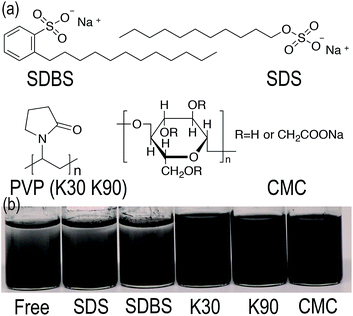 |
| | Fig. 1 (a) Chemical structures of the applied dispersants. (b) Digital images of GnP/EG suspensions respectively with free dispersant, SDS, SDBS, PVP-K30, PVP-K90 and CMC. | |
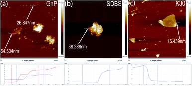 |
| | Fig. 2 Tapping-mode AFM images of GnP in suspensions respectively treated with (a) free dispersant (b) SDBS (c) PVP-K30. | |
Microstructures of GnP/PET nanocomposites
To confirm whether the preparation of homogenous GnP/PET nanocomposites was achieved through an in situ polymerization method, the cryogenic fractured surfaces of GP0, GP0.5 and GP2 were examined by FE-SEM and displayed in Fig. 3. As shown in Fig. 3(a), the unmodified PET (GP0) was characterized with smooth and featureless fracture surface. In comparison, the FE-SEM images of GnP/PET nanocomposites (GP0.5) revealed rough surfaces with GnP evenly embedded in the PET matrix. The rough fractured surface might be a result of crack distortion and thus, absorb more energy during fracturing according to the explanation described in the previous study.28 Meanwhile, the good dispersion of GnP was likely attributed by the addition of PVP-K30 in GnP/EG suspension and the application of the high shear compounding during the polymerization. Moreover, the π–π stacking interaction between GnP plane and PET matrix could be another reason to facilitate the even distribution of GnP in nanocomposites.29 On the other hand, the FE-SEM images of GP2 displayed an increased roughness of fractured surfaces when the content of GnP in the nanocomposite lifted to 2%, which was explained by the enhanced crack distortion. Nevertheless, there were no visible voids at the surface, suggesting the interfacial adhesion between GnP and PET matrix was still compact even at the high loading of GnP. However, there were still a small group of agglomerated GnPs detected in the 5k magnified images, meaning the dispersion ability of PVP-K30 was weaken along with the increased content of GnP. A worse agglomeration of GnPs was also recorded in the FE-SEM images of GP4, shown in Fig. 3(d). It was demonstrated that the homogenous GnP/PET nanocomposites with the addition volume of GnP lower than 2 wt% were prepared through the preliminary dispersion of GnP with PVP-K30 and the downstream in situ polymerization, thus avoiding the possible spinneret jam during the melt spinning.
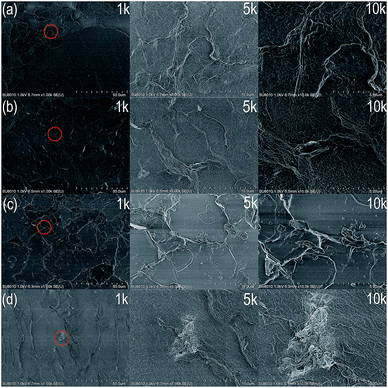 |
| | Fig. 3 FE-SEM images of cryogenic fractured surfaces of (a) GP0, (b) GP0.5, (c) GP2, (d) GP4 (the magnified images at the right side were corresponded to the area circled in the images at 1k of magnification). | |
Thermal properties of GnP/PET nanocomposites
The thermal behavior of PET and its nanocomposites with the concentration of GnP varying from 0.5% to 4% was studied by using TGA. In this study, TGA was performed to investigate the influences of GnP on the thermal stability of the resultant nanocomposites. Fig. 4 displayed TG curves of GnP/PET nanocomposites in nitrogen atmosphere. Table 2 summarized the results obtained from TGA measurements. It was shown that the introduction of GnP improved the thermal stability of the generated nanocomposites, which was evident from the lifted values on Td,5% and Td,max for GnP/PET nanocomposites. As presented in Table 2, the Td,5% of the nanocomposite samples was read at around 413.2 to 417.5 °C, approximately a 15 °C of increase compared to the unmodified PET. The Td,max was also correspondently increased at the similar level after incorporating GnP with PET matrix via an in situ polymerization method. As the unique planar structure of GnP can give a good performance on heat conductivity and thermal diffusivity, it has reportedly increased the degradation threshold for the GnP-dispersed nanocomposites.30 In addition, the enhanced thermal stability could also be associated with the built of an inflammable GnP network in PET matrix, which served as a thermal shield to retard the emission of decomposition substances during heating procedure.31 It was noteworthy that the residual weight of the nanocomposites proportionally increased along with the increased concentration of GnP being added, which further confirmed GnP was well-distributed in the PET matrix without precipitation before starting the polymerization.
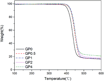 |
| | Fig. 4 TG curves of GnP/PET nanocomposites in nitrogen. | |
Table 2 Results for thermal properties of PET and GnP/PET nanocompositesa
| Sample |
Td,5% (°C) |
Td,max (°C) |
Residue (wt%) |
Tm (°C) |
Tc (°C) |
ΔHm (J g−1) |
Xc (%) |
| Note: Td,5% means the degradation temperature at 5% weight loss. Td,max means the temperature at the maximum degradation rate. Tm means melting temperature. Tc means crystallization temperature. ΔHm means heat fusion. Xc means degree of crystallinity. |
| GP0 |
399.5 |
435.9 |
16.1 |
253.5 |
180.6 |
42.9 |
30.6 |
| GP0.5 |
413.2 |
447.5 |
16.7 |
244.7 |
204.9 |
40.2 |
28.7 |
| GP1 |
417.5 |
453.9 |
16.8 |
245.1 |
206.1 |
41.2 |
29.4 |
| GP2 |
415.8 |
450.2 |
18.3 |
245.7 |
207.1 |
40.6 |
29.0 |
| GP4 |
414.5 |
445.8 |
20.9 |
246.7 |
210.3 |
41.8 |
29.9 |
The melting and crystallization behaviors of GnP/PET nanocomposites were examined through DSC measurements and presented in Fig. 5. The correspondent data including Tm, Tc, ΔHm, and Xc was summarized in Table 2. As listed in Table 2, the Tm values of the nanocomposites were ranged from 244.7 to 246.7 °C along with the increasing content of GnP, which was about 8 to 10 °C lower than that of unmodified PET. The results suggested that the presence of GnP produced positive influences on changing the melting behavior of GnP/PET nanocomposites and thus decreased their melt temperature for melt-spinning of fibers. The crystallization patterns compared the crystallization behavior between PET and GnP/PET nanocomposites, showing the nanocomposites exhibited higher Tc at 204.9 to 210.3 °C than the unmodified PET which was recorded to crystallize around at 180.6 °C. Moreover, the crystallization rate was also faster on the nanocomposites, which was evident from the narrow and sharp peaks observed in the patterns. The data demonstrated that the dispersed GnP in the nanocomposites served as a nucleating agent to accelerate the crystallization of PET. Xc was calculated by dividing the recorded heat fusion of the nanocomposites by the theoretical value of fully crystallized PET homopolymer.32 From the data shown in Table 2, it displayed that GnP/PET nanocomposites showed slightly lower Xc compared to the unmodified PET, meaning the addition of GnP could impede the formation of large PET crystalline grain and increase the amorphous region of the nanocomposites as its unique structure. Altogether, the improved thermal properties of GnP/PET nanocomposites have provided the guarantee to proceed the melt spinning afterwards.
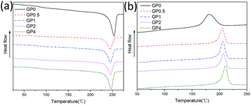 |
| | Fig. 5 Comparison of melting (a) and crystallization (b) behaviors between PET and GnP/PET nanocomposites. | |
Morphologies of melt-spun GnP/PET nanocomposite fibers
Unmodified PET fiber and its nanocomposite fibers containing different contents of GnP (undrawn yarns, UDY) were successfully spun by melt spinning technique. Melt spinning of GnP/PET nanocomposites has faced many challenges mostly due to the fact that fibers with small cross sectional area are quiet sensitive to agglomerated GnPs, impurities and voids, consequently affecting their properties and causing fiber breakage. To prevent the occurrence of these unexpected results, homogenous GnP/PET nanocomposites were prepared by an in situ melt polymerization method accompanied with the preliminary PVP-K30 treatment to GnP/EG suspensions. However, the maximum content of GnP in the nanocomposites limited to 2% as aggregated domains were observed at a higher level of GnP addition.
The surface and cross section morphologies of melt-spun GnP/PET fibers of UDY were imaged by FE-SEM and displayed in Fig. 6. As shown in Fig. 6(a), the unmodified PET fiber (FGP0) exhibited an even and smooth surface. By contrast, the fibers spun with the GnP/PET nanocomposites showed continuous but relatively rough surface that was shaped by the dispersed GnP in Fig. 6(b)–(d). It was also observed that the surface roughness of fibers increased along with the increasing GnP content in the nanocomposites, which might explain the reason that FGP4 was occasionally found having fiber breakage and filament defect during the melt spinning process. Fig. 6(e)–(h) showed FE-SEM images of the cross section morphologies of FGP0, FGP0.5, FGP2 and FGP4, revealing that the increase in the content of GnP raised the roughness of cross section of the nanocomposite fibers, which was consistent with the results observed on the surface. The magnified FE-SEM images assigned to the cross section of each fiber were further recorded to investigate the effects of GnP on the axial orientation of fibers which were known being critically related to their final mechanical properties. As seen in Fig. 6(j), FGP0.5 showed an uniform dispersion of GnP in PET matrix. However, the GnP in FGP2 and FGP4 appeared to be buckled, deformed and folded in Fig. 6(k) and (l). We speculated that, GnP exhibited a certain degree of axial orientation on FGP0.5 but weaker one when the content of GnP was added up to 4%, indicating the presence of overloaded GnP was likely to produce negative effects on the axial orientation of the nanocomposite fibers and thus may weaken the mechanical properties.
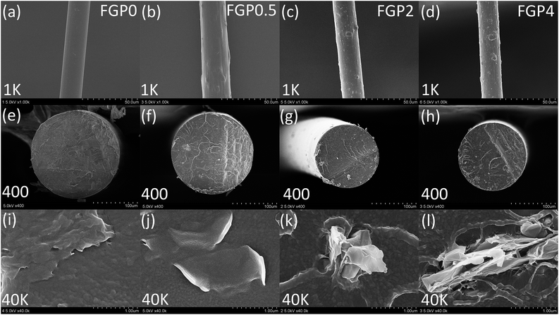 |
| | Fig. 6 FE-SEM images of (a)–(d) surface and (e)–(l) cross section morphologies of FGP0, FGP0.5, FGP2 and FGP4. | |
2D-WAXS patterns of melt-spun GnP/PET nanocomposite fibers
To further study the orientation of GnP in its PET matrix nanocomposite fibers, the amorphous and crystalline structure of GnP, unmodified PET fiber and GnP/PET nanocomposite fibers with the melt-drawing ratio of 4.1 in nanometer scale were analyzed by WAXS and shown in Fig. 7. The WAXS pattern of GnP exhibited a strong concentric circle, indicating that GnP only possessed an isotropic crystalline phase. Instead, the WAXS pattern of GnP-free FGP0-4.1 showed a typical diffraction arcs of PET, which revealed that the amorphous and crystalline phases simultaneously existed in the FGP0 with a certain degree of orientation acquired.33 By comparison, FGP0.5-4.1 gave an identical WAXS pattern with FGP0-4.1 when having 0.5% of GnP loading, which might be due to the small quantity of GnP that was insufficient to display the signals. However, with the content of GnP further increasing, the WAXS pattern of FGP2-4.1 exhibited a weak diffraction arc that was corresponded to GnP along with strong characteristic diffraction arc assigned to PET, suggesting a small group of isotropic GnPs could regularly arrange along the fiber axis to achieve a certain level of orientation after the spinning and stretching processes were applied. But it had to note that the exact orientation value of GnP was unable to be given as the weak diffraction arc of GnP closely overlapped with the one of PET in the pattern.
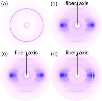 |
| | Fig. 7 2D-WAXS patterns of (a) GnP, (b) FGP0-4.1, (c) FGP0.5-4.1, and (d) FGP2-4.1. | |
Mechanical properties of melt-spun GnP/PET nanocomposite fibers
The mechanical properties of the melt-spun PET and GnP/PET nanocomposite fibers at different drawing ratios were shown in Fig. 8 and 9 where the correspondent results were summarized in Table 3. Generally, increasing melt-drawing ratios would lead to the improvement on tenacity but the reduction on elongation at break for the fibers.34 As observed in Fig. 8, the unmodified PET and all the GnP/PET fibers, only except FGP4, confirmed the fact that their tenacity indeed shifted to higher values after the melt-drawing ratios were risen up. The exception occurred on FGP4 might be due to the presence of massive agglomerated GnPs that thereby hampered the reinforcement to the fiber. Nevertheless, the elongation at break was expectedly decreased with the increased melt-drawing ratios in all the tested fibers. Theoretically, an appropriate quantity of GnP added in the polymer matrix normally results in improved mechanical properties. Compared to FGP0, FGP0.5 displayed similar tenacity at low melt drawing ratios (3.5 and 3.7) but decreased values at higher ones, suggesting 0.5% of GnP gave little assistance in reinforcing its melt spun fiber in the current system and was also limited by the melt drawing ratio which likely destructed the interfacial interaction between GnP and PET matrix. As the content of GnP further increased, the GnP/PET fibers with different drawing ratios continued to reduce tenacity. Specially, the tenacity of FGP4 containing 4% GnP reached the lowest value at the highest drawing ratio, suggesting the presence of higher level of GnP would magnify the negative effects on the strength of its fibers as the large content of GnP could create more breaking points when fibers were stretched. The elongation at break of the melt-spun GnP/PET fibers, however, increased as compared with that of unmodified PET fiber, which might be explained by the bumper function that GnP acted in PET matrix as it was particularly constructed by multilayers of graphene.
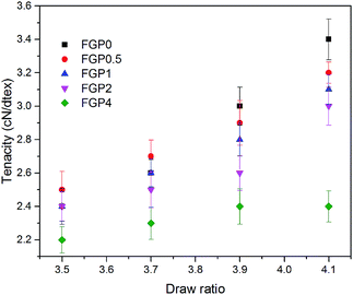 |
| | Fig. 8 Tenacity of melt-spun PET and GnP/PET nanocomposite fibers with different draw ratios. | |
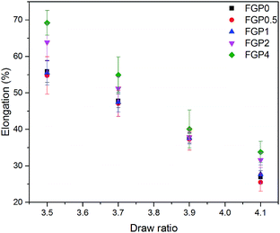 |
| | Fig. 9 Elongation at break of melt-spun PET and GnP/PET nanocomposite fibers with different drawing ratios. | |
Table 3 Data for the mechanical properties of all melt-spun fibers with different drawing ratios
| Sample |
Drawing ratio |
Linear density (dtex)/36f |
Tenacity (cN/dtex) |
Tenacity CV (%) |
Elongation (%) |
Elongation CV (%) |
| FGP0 |
3.5 |
140.7 |
2.4 |
4.5 |
55.9 |
5.4 |
| 3.7 |
132.8 |
2.6 |
3.1 |
47.8 |
3.9 |
| 3.9 |
125.6 |
3.0 |
3.9 |
37.5 |
3.9 |
| 4.1 |
120.1 |
3.4 |
3.7 |
26.9 |
4.1 |
| FGP0.5 |
3.5 |
145.9 |
2.5 |
4.4 |
54.8 |
9.4 |
| 3.7 |
136.8 |
2.7 |
3.6 |
47.1 |
7.6 |
| 3.9 |
130.3 |
2.9 |
4.6 |
37.3 |
8.0 |
| 4.1 |
125.5 |
3.2 |
2.0 |
25.5 |
9.7 |
| FGP1 |
3.5 |
145.7 |
2.4 |
3.7 |
55.5 |
6.0 |
| 3.7 |
137.4 |
2.6 |
3.3 |
47.5 |
5.8 |
| 3.9 |
131.9 |
2.8 |
3.5 |
37.6 |
4.0 |
| 4.1 |
126.8 |
3.1 |
2.9 |
27.7 |
9.2 |
| FGP2 |
3.5 |
156.2 |
2.4 |
3.6 |
63.9 |
8.1 |
| 3.7 |
148.5 |
2.5 |
4.3 |
51.2 |
6.3 |
| 3.9 |
140.8 |
2.6 |
4.0 |
37.9 |
4.0 |
| 4.1 |
133.6 |
3.0 |
3.8 |
31.6 |
6.6 |
| FGP4 |
3.5 |
159.7 |
2.2 |
3.4 |
69.2 |
4.9 |
| 3.7 |
150.8 |
2.3 |
4.2 |
54.9 |
9.1 |
| 3.9 |
142.3 |
2.4 |
4.4 |
40.1 |
13.0 |
| 4.1 |
133.4 |
2.4 |
3.9 |
33.8 |
8.6 |
Antistatic properties of melt-spun GnP/PET nanocomposite fibers
As mentioned previously, one of the primary purposes of adding GnP in the polymer matrix is to enhance the electric conductivity of their generated nanocomposites. To test whether GnP was achieved to change the antistatic ability of its nanocomposite fibers in the current system, the volume resistivity of the melt-spun fibers with or without GnP was measured and depicted in Fig. 10 where the detailed values were summarized in Table 4. Through observing the plotted curves in Fig. 10, it was clearly shown that the volume resistivity of the fibers varied with the content of GnP. As presented in Table 4, the volume resistivity of unmodified PET fiber at 25 °C and RH 60% was about 1.8 × 10¹⁴ Ω cm. In comparison, GnP/PET fibers exhibited substantially decreased volume resistivity from 5.7 × 10⁸ to 6.7 × 10⁷ Ω cm with an increase of GnP loading from 0.5 to 4% under the same testing condition. The obtained results indicated that the π–π stacking interaction built between the π-orbitals of conjugated PET chains and the sp2-orbitals in the dispersed GnP plane could form an electrical conduction path in the nanocomposite fibers and thus reduce the barriers for the electron transport amid the fibers.
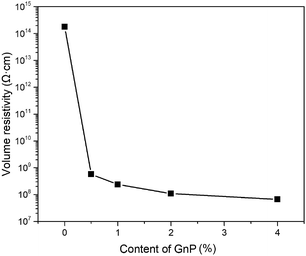 |
| | Fig. 10 Volume resistivity of PET and GnP/PET nanocomposite fibers. | |
Table 4 Detailed values for volume resistivity of PET and GnP/PET nanocomposite fibers
| Sample |
Volume resistivity (Ω cm) |
| FGP0 |
1.8 × 10¹⁴ |
| FGP0.5 |
5.7 × 10⁸ |
| FGP1 |
2.4 × 10⁸ |
| FGP2 |
1.1 × 10⁸ |
| FGP4 |
6.7 × 10⁷ |
Conclusions
GnP/PET nanocomposite fibers were successfully spun with in situ polymerized GnP/PET nanocomposites by melt spinning technique. The homogenous PET matrix nanocomposites containing the content of GnP below 2% were generated due to the application of preliminary PVP-K30 treatment to GnP/EG suspensions and melt compounding during the in situ polymerization. As featured with good heat conductivity and thermal diffusivity, GnP improved the thermal properties of its PET nanocomposites, which thereby favorably proceeding of the melt spinning of fibers afterwards. Although the surface roughness of the melt-spun nanocomposite fibers increased with an increase in GnP loading, there was no fiber breakage or filament defect observed on FGP0.5, FGP1 and FGP2. In addition, the incorporation of GnP at the content of 0.5% had similar tenacity with unmodified PET fiber but reversely reduced the tenacity when the loading further increased. Most importantly, the melt-spun GnP/PET nanocomposite fibers exhibited much lower volume resistivity compared to unmodified PET fiber, reinforcing its potential to be used in antistatic textile and military industries.
Acknowledgements
This work was financially supported by the National Natural Science Foundation of China (61134009), National Basic Research Program of China (2013BAE01B02), and the National Key Research and Development Program of China (2016YFB0302702). We also thank Shandong Shengquan Group Co., Ltd. and Shuang Liang Eco-energy Co., Ltd. (Jiangsu, China) for providing the timely help during the study.
References
- J. Faucheu, C. Gauthier, L. Chazeau, J. Y. Cavaillé, V. Mellon and E. B. Lami, Polymer, 2010, 51, 6–17 CrossRef CAS.
- S. H. Park and P. R. Bandaru, Polymer, 2010, 51, 5071–5077 CrossRef CAS.
- P. Ji, C. Wang, Z. Jiang and H. Wang, Polym. Compos., 2016, 37, 1830–1838 CrossRef CAS.
- Y. Zhu, S. Murali, W. Cai, X. Li, J. W. Suk, J. R. Potts and R. S. Ruoff, Adv. Mater., 2010, 22, 3906–3924 CrossRef CAS PubMed.
- A. K. Geim and K. S. Novoselov, Nat. Mater., 2007, 6, 183–191 CrossRef CAS PubMed.
- X. Wang, P. D. Bradford, W. Liu, H. Zhao, Y. Inoue, J.-P. Maria, Q. Li, F.-G. Yuan and Y. Zhu, Compos. Sci. Technol., 2011, 71, 1677–1683 CrossRef CAS.
- H.-B. Zhang, W.-G. Zheng, Q. Yan, Y. Yang, J.-W. Wang, Z.-H. Lu, G.-Y. Ji and Z.-Z. Yu, Polymer, 2010, 51, 1191–1196 CrossRef CAS.
- G. Chen, D. Wu, W. Weng and C. Wu, Carbon, 2010, 41, 579–625 Search PubMed.
- G. Chen, W. Weng, D. Wu, C. Wu, J. Lu, P. Wang and X. Chen, Carbon, 2004, 42, 753–759 CrossRef CAS.
- D. D. L. Chung, J. Mater. Sci., 2016, 51, 554–568 CrossRef CAS.
- A. M. Abdelkader, A. J. Cooper, R. A. W. Dryfe and I. A. Kinloch, Nanoscale, 2015, 7, 6944–6956 RSC.
- M. Karevan and K. Kalaitzidou, Compos. Interfaces, 2013, 20, 255–268 CrossRef CAS.
- J.-L. Zeng, S.-H. Zheng, S.-B. Yu, F.-R. Zhu, J. Gan, L. Zhu, Z.-L. Xiao, X.-Y. Zhu, Z. Zhu, L.-X. Sun and Z. Gao, Appl. Energy, 2014, 115, 603–609 CrossRef CAS.
- X. Zhang, Z. Yao, Z. Ge, K. Yao, R. Tao, T. Yu and J. Han, J. Test. Eval., 2017, 45, 20160026 Search PubMed.
- F. D. Santis, R. Pantani, V. Speranza and G. Titomanlio, Ind. Eng. Chem. Res., 2010, 49, 2469–2476 CrossRef.
- H. Shin and E.-S. Park, J. Appl. Polym. Sci., 2009, 114, 3008–3015 CrossRef CAS.
- F. Fraternali, I. Farina, C. Polzone, E. Pagliuca and L. Feo, Composites, Part B, 2013, 46, 207–210 CrossRef CAS.
- H.-J. Lee, S.-J. Oh, J.-Y. Choi, J. W. Kim, J. Han, L.-S. Tan and J.-B. Baek, Chem. Mater., 2005, 17, 5057–5064 CrossRef CAS.
- V. B. Gupta, J. Radhakrishnan and S. K. Sett, Polymer, 1994, 35, 2560–2567 CrossRef CAS.
- H. A. Hristov and J. M. Schultz, J. Polym. Sci., Polym. Phys. Ed., 1990, 28, 1647–1663 CrossRef CAS.
- S. Melinte and A. Jeflea, Macromol. Mater. Eng., 2001, 286, 196–200 CrossRef CAS.
- H. J. Yoo, K. H. Kim, S. K. Yadav and J. W. Cho, Compos. Sci. Technol., 2012, 72, 1834–1840 CrossRef CAS.
- A. Greco, F. Lionetto and A. Maffezzoli, IEEE Trans. Nanotechnol., 2016, 15, 877–883 CrossRef CAS.
- Z. Li, G. Luo, F. Wei and Y. Huang, Compos. Sci. Technol., 2006, 66, 1022–1029 CrossRef CAS.
- K. Liu, L. Chen, Y. Chen, J. Wu, W. Zhang, F. Chen and Q. Fu, J. Mater. Chem., 2011, 21, 8612–8617 RSC.
- O. V. Kharissova, B. I. Kharisov and E. G. C. Ortiz, RSC Adv., 2013, 3, 24812–24852 RSC.
- F. Bourdiol, F. Mouchet, A. Perrault, I. Fourquaux, L. Datas, C. Gancet, J.-C. Boutonnet, E. Pinelli, L. Gauthier and E. Flahaut, Carbon, 2013, 54, 175–191 CrossRef CAS.
- B. W. Steinert and D. R. Dean, Polymer, 2009, 50, 898–904 CrossRef CAS.
- J. Bian, H. Lin, F. He, L. Wang, X. Wei, I.-T. Chang and E. Sancaktar, Eur. Polym. J., 2013, 49, 1406–1423 CrossRef CAS.
- J. Gu, N. Li, L. Tian, Z. Lv and Q. Zhang, RSC Adv., 2015, 5, 36334–36339 RSC.
- J. Gu, J. Du, J. Dang, W. Geng, S. Hu and Q. Zhang, RSC Adv., 2014, 4, 22101–22105 RSC.
- W. C. Oliver and G. M. Pharr, J. Mater. Res., 1992, 7, 1564–1583 CrossRef CAS.
- E. Gorlier, J. M. Haudin and N. Billon, Polymer, 2001, 42, 9541–9549 CrossRef CAS.
- A. Rizvi, Z. K. M. Andalib and C. B. Park, Polymer, 2017, 110, 139–148 CrossRef CAS.
|
| This journal is © The Royal Society of Chemistry 2017 |
Click here to see how this site uses Cookies. View our privacy policy here.  Open Access Article
 ,
Chaosheng Wang*,
Biao Wang,
Ye Chen and
Huaping Wang
![[thin space (1/6-em)]](https://www.rsc.org/images/entities/char_2009.gif) :
:![[thin space (1/6-em)]](https://www.rsc.org/images/entities/char_2009.gif) 1.25 of feed molar ratio with EG where the catalyst (Sb2EG3) and thermal stabilizer (triphenyl phosphate) were supplemented simultaneously. After constant stirring at room temperature for 0.5 h, the resulting mixture was added into the reactor which was subsequently heated to 235–245 °C at a slow rate for allowing the esterification reaction to proceed for 3–3.5 h. Once this reaction step ended, vacuum was applied and adjusted to gradually decrease the pressure to 500 Pa within 45 min while the temperature of reactor was lifted to 265 °C. Thereafter, polycondenzation process occurred through further increasing the reactor's temperature to 280 °C and reducing the pressure to 50 Pa, a reaction step that was required to proceed for 1.5–2 h to complete the synthesis of GnP/PET nanocomposites. In our study, the unmodified PET was synthesized under the same conditions only without the loading of GnP. The nanocomposites with the content of GnP at 0, 0.5, 1, 2 and 4 wt% were labeled as GP0, GP0.5, GP1, GP2 and GP4, respectively. The intrinsic viscosity of GP0, GP0.5, GP1, GP2 and GP4 were measured to be 0.72, 0.74, 0.73, 0.71, and 0.66 dl g−1.
1.25 of feed molar ratio with EG where the catalyst (Sb2EG3) and thermal stabilizer (triphenyl phosphate) were supplemented simultaneously. After constant stirring at room temperature for 0.5 h, the resulting mixture was added into the reactor which was subsequently heated to 235–245 °C at a slow rate for allowing the esterification reaction to proceed for 3–3.5 h. Once this reaction step ended, vacuum was applied and adjusted to gradually decrease the pressure to 500 Pa within 45 min while the temperature of reactor was lifted to 265 °C. Thereafter, polycondenzation process occurred through further increasing the reactor's temperature to 280 °C and reducing the pressure to 50 Pa, a reaction step that was required to proceed for 1.5–2 h to complete the synthesis of GnP/PET nanocomposites. In our study, the unmodified PET was synthesized under the same conditions only without the loading of GnP. The nanocomposites with the content of GnP at 0, 0.5, 1, 2 and 4 wt% were labeled as GP0, GP0.5, GP1, GP2 and GP4, respectively. The intrinsic viscosity of GP0, GP0.5, GP1, GP2 and GP4 were measured to be 0.72, 0.74, 0.73, 0.71, and 0.66 dl g−1.
![[thin space (1/6-em)]](https://www.rsc.org/images/entities/char_2009.gif) :
:![[thin space (1/6-em)]](https://www.rsc.org/images/entities/char_2009.gif) 1, w/w) as solvent. Before the intrinsic viscosity test, the solution was filtered to remove GnP through polytetrafluoroethylene microporous membrane. AFM was recorded on a Bruker atomic force microscopy (AFM) in tapping mode. TGA measurements were carried out on a TA Q500 instruments under a dry nitrogen flow at a heating rate of 10 °C min−1, from room temperature to 600 °C followed by the residues were naturally cooled down to the normal temperature. DSC analysis was performed on a TA Q20 instrument under nitrogen atmosphere at a heating (cooling) scan rate of 10 °C min−1 (25–285 °C). The morphologies of GnP/PET nanocomposites were observed using a S-4800 field emission scanning electron microscope (FE-SEM) after coated with conductive gold. The mechanical property of fiber was studied by XL-1 multifilament strength machine. Volume resistivity was measured by XR-1A Fiber Specific Resistance Tester at 25 °C and RH 60%. Synchrotron X-ray measurements were carried out at Shanghai Synchrotron Radiation Facility (SSRF) on beam line (BL16B) at an X-ray wavelength of 0.124 nm. Two-dimensional (2D) wide-angle X-ray scattering technique (WAXS) patterns were acquired using a Mar-CCD (165) detector with the distance of sample-to-detector set at 137.61 mm.
1, w/w) as solvent. Before the intrinsic viscosity test, the solution was filtered to remove GnP through polytetrafluoroethylene microporous membrane. AFM was recorded on a Bruker atomic force microscopy (AFM) in tapping mode. TGA measurements were carried out on a TA Q500 instruments under a dry nitrogen flow at a heating rate of 10 °C min−1, from room temperature to 600 °C followed by the residues were naturally cooled down to the normal temperature. DSC analysis was performed on a TA Q20 instrument under nitrogen atmosphere at a heating (cooling) scan rate of 10 °C min−1 (25–285 °C). The morphologies of GnP/PET nanocomposites were observed using a S-4800 field emission scanning electron microscope (FE-SEM) after coated with conductive gold. The mechanical property of fiber was studied by XL-1 multifilament strength machine. Volume resistivity was measured by XR-1A Fiber Specific Resistance Tester at 25 °C and RH 60%. Synchrotron X-ray measurements were carried out at Shanghai Synchrotron Radiation Facility (SSRF) on beam line (BL16B) at an X-ray wavelength of 0.124 nm. Two-dimensional (2D) wide-angle X-ray scattering technique (WAXS) patterns were acquired using a Mar-CCD (165) detector with the distance of sample-to-detector set at 137.61 mm.


