 Open Access Article
Synthesis of novel sulfonated poly(arylene ether)s containing a tetra-trifluoromethyl side chain and multi-phenyl for proton exchange membrane fuel cell application†
Yi-Chiang Huang ,
Hsu-Feng Lee,
Yu-Chao Tseng,
Chun-Che Lee,
Mei-Ying Chang and
Wen-Yao Huang*
Department of Photonics, National Sun Yat-Sen University, No. 70, Lienhai Rd., Kaohsiung 80424, Taiwan. E-mail: wyhuang@faculty.nsysu.edu.tw
First published on 29th June 2017
Abstract
Herein, a series of novel sulfonated poly(arylene ether)s consisting of tetra-trifluoromethyl-substituted multi-phenyl was synthesized via polycondensation, and post-sulfonation was carried out through chlorosulfonic acid to obtain sulfonated polymers possessing ion exchange capacities ranging from 1.27 to 2.53 mmol g−1. 1H NMR and FTIR spectroscopy were applied to confirm the structure and composition of the sulfonated polymers. The membranes exhibited considerable dimensional stability (with 3.1–27.8% change in length; 17–56.5% change in thickness at 80 °C) and excellent oxidative stability (weight remained higher than 97%). The mechanical properties of the membranes demonstrated good tensile strength on account of the highly rigid multi-phenylated backbone, and Young's modulus ranged from 0.65 to 0.88 GPa. The proton conductivities of the membranes ranged from 0.03 to 0.24 S cm−1 at 80 °C under 95% RH, which were comparable to or higher than those of Nafion 211. The morphology of the membranes demonstrated a clear hydrophilic/hydrophobic phase separation with spherical ionic clusters in the size range of 5–20 nm. SFC2-2.53 demonstrated a high current density (around 1800 mA cm−2 at 0.6 V) and the maximum power density of 1.41 W cm−2 for the fuel cell performance. The results indicated that SFC2 would be a good candidate for proton exchange membranes in fuel cell applications.
Introduction
A fuel cell (FC) converts chemical energy directly from a fuel into electricity, and has been presented as a promising alternative power source due to its high fuel conversion efficiency and low amount of pollutants.1,2 Proton exchange membrane fuel cells (PEMFCs) have received significant attention because of their low operation temperature/pressure ranges. Several important features of the PEMFCs depend upon the properties of the proton exchange membranes (PEMs). Therefore, PEMs are required to possess some of the following properties: high proton conductivity, low fuel and oxidant permeability, adequate electrochemical and chemical stability under FC operation conditions, dimensional and morphological stability, good mechanical properties, a satisfactorily low cost, and sufficient long term durability.3,4Currently, Nafion membranes, which are perfluorinated sulfonic acid (PFSA) ionomer membranes, from DuPont are deemed to be the most suitable PEMs and dominate the most demonstrated and commercialized PEMFC market owing to their good chemical and electrochemical stability as well as excellent proton conductivity. However, there are some disadvantages associated with Nafion: poor thermomechanical and chemical stability and decrease in the proton conductivity above 90 °C and under low humidity conditions. Moreover, the worst disadvantage is high material costs due to expensive fluorination and complex manufacturing processes.5–8 In recent years, sulfonated hydrocarbon polymers have attracted significant attention as alternative polymer electrolyte membranes to Nafion. These sulfonated polymers, such as sulfonated poly(arylene ethers), sulfonated poly(arylene ether ketone)s, sulfonated polyimides, and sulfonated polybenzimidazoles,9,10 have been extensively investigated owing to the easy adjustment of their molecule structure, high thermal stability, good chemical stabilities, appropriate mechanical properties, processability, and low production cost.11–13
In general, sulfonated aromatic hydrocarbon polymers under high ion exchange capacity (IEC) can provide good proton conductivity and water uptake. However, high IEC value of PEMs is frequently accompanied by excessive swelling and deteriorated mechanical properties.14 Recently, we have reported a series of poly(arylene ether)s containing a high free volume multi-phenylated structure in the polymer backbone, which provides water sorption ability while maintaining mechanical and dimensional stability and demonstrates high proton conductivity.15–17 Skalski et al. synthesized a sulfonated polyphenylene homopolymer with a high IEC value of 3.70 mmol g−1. The membranes were water-insoluble and exhibited higher proton conductivity as compared to Nafion 211 in the range of 50–95% RH.18 Lim et al. reported a sulfonated poly(arylene ether ketone sulfone) block copolymer that consisted of non-planar conformation and a non-conjugated multi-phenyl monomer. The membranes showed high water uptake and comparable proton conductivity as compared to Nafion 211. This result may be attributed to well-defined phase separation.19 As observed from many reported researches, partially fluorinated sulfonated polymers have demonstrated some advantages over non-fluorinated sulfonated polymers. The presence of fluorine substitution is expected to lead to good chemical stability and better hydrophilic/hydrophobic phase separation.8,20,21 Furthermore, the fluorine substituted group is a strongly electron-withdrawing group, which can deactivate the aromatic ring to prevent the attack of the sulfonating agent.22,23
Herein, we report the synthesis of novel poly(arylene ether)s composed of trifluoromethyl side chains on multi-phenylated bisfluoro monomer with fluorene-based and multi-phenylated bisphenol monomers. The trifluoromethyl group enables the deactivation of the aromatic ring to restrict the position of sulfonation and to increase phase separation and chemical stability. The high free volume of the multi-phenylated structure provides water sorption ability and preserves mechanical stability. The sulfonated poly(arylene ether)s were prepared via treatment with chlorosulfonic acid and confirmed by 1H NMR and FTIR spectroscopies. The membranes were prepared via solution casting from dimethyl sulfoxide, and their PEM properties such as water uptake, dimensional stability, mechanical strength, proton conductivity, morphology, and single cell performance were characterized.
Experimental
General methods
All reagents and solvents were purchased from Alfa Aesar, Aldrich Chemical Co., Merck, Lancaster, Fisher Scientific or Tokyo Chemical Industry Co. and used without further purification. Toluene was dried over CaH and freshly distilled under a N2 atmosphere and deoxygenated by purging with N2 for 20 min prior to use. All reactions were performed under a pre-purified N2 atmosphere. The synthesis of 4,4′-(9,9′-spirobi[fluorene]-2,7-diyl)diphenol and 2′′,3′′,5′′,6′′-tetraphenyl-[1,1′:4′,1′′:4′′,1′′′:4′′′,1′′′′-quinquephenyl]-4,4′′′′-diol was carried out by following the previously reported procedures.16,24,25General procedure for the synthesis of FC polymers
Polymerization reactions were carried out in a three-necked 100 mL flame-dried flask equipped with a stirring bar and a Dean-Stark apparatus fitted with a condenser under a N2 atmosphere. The flask was charged with M1 (2.33 mmol), bisphenol monomer (2.33 mmol), potassium carbonate (0.8 g, 5.78 mmol), dimethylacetamide (DMAC) (20 mL), and toluene (15 mL). The reaction mixture was stirred at 130 °C for 2 h to remove toluene and water; then, the reaction temperature was increased to 160 °C for 24 h. After being cooled down to room temperature, the crude mixture was poured in methanol and deionized water to precipitate a light yellow-white fibrous polymer. The polymer was filtered, washed several times with water and hot methanol, and dried in vacuum at 80 °C for 8 h.General procedure for sulfonation
To a solution of the polymer (1.2 g) in dichloromethane (75 mL) at room temperature, chlorosulfonic acid in dichloromethane was added drop-wise. The reaction mixture was stirred for 24 h and then poured in water. The polymer precipitate was filtered, washed thoroughly with deionized water until pH became neutral, and then dried in vacuum at 60 °C overnight to obtain the sulfonated polymer. To prepare variety degrees of sulfonation, polymers were sulfonated to different extents according to the above procedure by adding 6 mL and 14 mL of chlorosulfonic acid, respectively. The sulfonated polymer was readily soluble in polar aprotic solvents such as DMF, DMAC, DMSO, and NMP.The ion exchange capacity (IEC) of the membranes was determined by acid–base titration. The dried membrane was weighted and immersed in 1.0 M HCl solution for 24 h to protonate the acid groups and washed thoroughly with deionized water to reach a neutral pH. Then, the membrane was immersed in a 1.0 M solution of NaCl for 24 h, such that to replace the protons of sulfonic acid groups by Na ions. The solutions were titrated using a 0.01 M NaOH solution, and phenolphthalein was used as an indicator. The IEC (mmol g−1) values were calculated from the titration results using the following equation: IEC (mmol g−1) = (VNaOH × MNaOH)/Wdry, where VNaOH and MNaOH are the volume and concentration of the NaOH solution, respectively, and Wdry is the weight of the dry membrane.
Measurements
1H NMR and 19F NMR spectroscopic measurements were carried out via a 500 MHz Varian UNITY INOVA-500 spectrometer using CDCl3 or DMSO-d6 as the solvent. MALDI-TOF mass spectrum was obtained via a Bruker Daltonics, autoflex III TOF/TOF using 2,5-dihydroxybenzoic acid as the matrix. FTIR spectrum of the polymer membranes was obtained using a Bruker VERTEX 70 FTIR spectrometer. The gel permeation chromatographic (GPC) analysis was carried out using Viscotek 270 max with a refractive index detector (Viscotek model 270, THF used as the eluent, flow rate of 1 mL min−1). For calibration, polystyrene standard (molecular weight between 6770 and 281000 Da) was used. Thermal stability of the polymers was evaluated via thermogravimetric analysis (TGA) that was carried out using a Perkin Elmer Pyris 1 instrument from 50 °C to 800 °C at a heating rate of 10 °C min under a N2 atmosphere. Before the analysis, the membranes were dried in the TGA furnace at 130 °C under N2 for 20 min to remove water. Thermal mechanical analyses (TMA) were performed on film specimens (length, 10 mm; width, 2 mm; and thickness, 30–40 μm) using the Seiko Pyris Diamond TMA at 25 °C.Water uptake and dimensional stability
Water uptake was the measured weight from the mass increase of the membranes immersed in deionized water for 24 h as the temperature increased from 30 to 80 °C. The water uptake was calculated using the following equations.| Water uptake (%) = (Wwet − Wdry)/Wdry × 100% |
The swelling ratio was measured from the change in the dimension of membranes immersed in deionized water for 24 h as the temperature was increased from 30 to 80 °C and calculated using the following equations:
| In plane swelling ratio (%): ΔL = (Lwet − Ldry)/Ldry × 100% |
| Through plane swelling ratio (%): ΔT = (Twet − Tdry)/Tdry × 100% |
Stability
The membranes were weighed and soaked in Fenton's reagent (3% H2O2 aqueous solution containing 2 ppm FeSO4) at 80 °C for 1 h. The oxidative stability was evaluated by change in the weight of the membranes after being attacked by the Fenton's reagent. Hydrolytic stability of the membranes was evaluated by immersing the membranes in water at 140 °C for 24 h.Proton conductivity
The proton conductivity measurements of the membranes were conducted using an AC impedance analyzer (Agilent 4294A Precision Impedance Analyzer) along the in-plane direction over a frequency range of 10 M to 100 Hz at a voltage amplitude of 100 mV. The conductivity was measured after clamping a 10 × 20 mm sample piece between two platinum electrodes of a conductivity cell. The test cell was placed in a FIRSTEK BTH80/-20 environmental chamber to measure conductivity at 80 °C with varied relative humidity. Proton conductivity (σ) was then calculated by the equation σ = L/RA, where L (cm) is the distance between electrodes, R (Ω) is the membrane resistance, and A (cm2) is the cross-sectional area of the sample.Microstructure analysis
Transmission electron microscopy (TEM) was performed using a JEOL, JEM-2100 (HR) TEM, operated at an accelerating voltage of 200 kV. For this study, the acid form of the membranes was stained and converted into Ag+ ion via overnight immersion in 1 M AgNO3. Subsequently, the membranes were washed thoroughly with deionized water and dried at room temperature for 24 h. The stained membranes were placed in an enclosure of epoxy resin and ultra-microtomed under cryogenic conditions with a thickness of 70 nm.Single cell performance
Catalyst inks were prepared by mixing Pt/C (HiSPEC 4000, Alfa Aesar) and 5 wt% Nafion D520 binder. The ink was loaded on both sides of the membrane via a spraying method. The active surface area was 5 cm2 with an overall Pt loading of 0.4 mg cm−2. The membrane electrolyte assemble (MEA) was obtained via the construction of the SFC membrane sandwiched between two gas diffusion layers (GDL 24BC, Hephas Energy Co., Ltd.). The MEA of the Nafion 211 membrane was fabricated via the same procedure as a reference. The anode and cathode were supplied with hydrogen at a flow rate of 0.3 L min−1 and oxygen at a flow rate of 0.5 L min−1, respectively. The fabricated cell was activated for 5 h with hydrogen and oxygen at 80 °C and 100% relative humidity.Results and discussion
Synthesis and characterization of the monomers and polymers
A novel tetra-trifluoromethyl side chain-substituted monomer was successfully synthesized via three synthetic steps, as shown in Scheme 1. The monomer 1 was synthesized from 1,3-bis(4-bromophenyl)propan-2-one and 3,3′′-bis(trifluoromethyl)benzil via aldol condensation. Then, the monomer 1 was reacted with 2,5-norbornadiene via Diels–Alder reaction to obtain monomer 2. Finally, 4,4′′′′-difluoro-3,3′′′′-bis(trifluoromethyl)-2′′,3′′,-bis(trifluoromethyl) phenyl-[1,1′:4′,1′′:4′′,1′′′:4′′′,1′′′′-quinquephenyl] (monomer 3) was prepared from monomer 2 and 4-fluoro-3-trifluoromethyl phenyl boronic acid through Suzuki coupling. The monomers were confirmed via 1H NMR and MALDI-TOF MS spectroscopy, as shown in the ESI.† | ||
| Scheme 1 Synthesis of monomer (a) Triton B, triethylene glycol, 120 °C (b) toluene, reflux (c) Pd(PPh3)4, THF, toluene, K2CO3, reflux. | ||
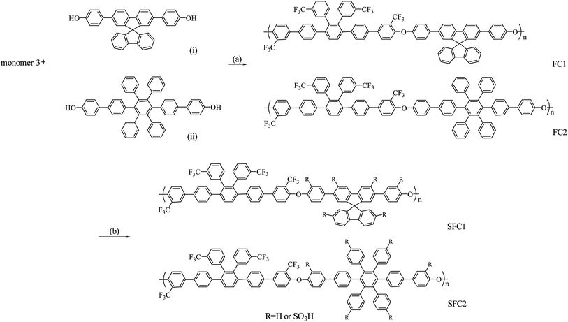
The polymers were prepared via a one-pot nucleophilic polycondensation with monomer 3 and diol monomers, 4,4′-(9,9′-spirobi[fluorene]-2,7-diyl)diphenol and 2′′,3′′,5′′,6′′-tetraphenyl-[1,1′:4′,1′′:4′′,1′′′:4′′′,1′′′′-quinquephenyl]-4,4′′′′-diol, which were denoted as FC1 and FC2, respectively, as shown in Scheme 2. The obtained polymers were readily soluble in common solvents such as DMAc, NMP, THF, and chloroform. The molecular weight of the polymers was determined by gel permeation chromatography (GPC). The FC1 and FC2 showed high molecular weight of 245 and 150 kDa and polydispersity index (PDI) of 4.0 and 3.7, respectively. These results indicated that the 2-perfluoroalkyl substitution in the phenyl groups activating the ortho-fluoro displacement was sufficient to obtain high molar mass poly(arylene ether)s during polymerization.26,27
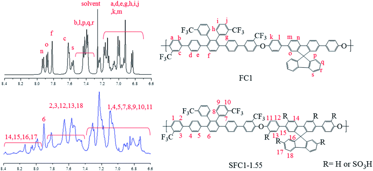
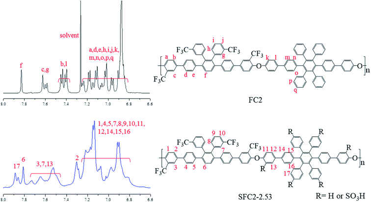
Post-sulfonation of the FC polymers was carried out using various degrees of chlorosulfonic acid to obtain SFC1-X and SFC2-X, where X represents the value of IEC, and the structures were confirmed by the 1H NMR spectrum. NMR signals of SFC1-1.55 and SFC2-2.53 are shown in Fig. 1 and 2, respectively. Generally, substitution reaction by chlorosulfonic acid preferentially occurs on electron-rich aromatic rings. The new signal appears at 7.75 ppm due to the presence of the sulfonic acid group (labeled 13). The new signal at 7.9 ppm is assigned to the proton next to the sulfonated pendant benzene ring (labeled 17), showing a similar chemical shift as reported in our previous work.15,17 The 19F-NMR spectrum showed the signals of the trifluoromethyl group of unsulfonated polymers that were assigned to be at −66 and −68 ppm. After sulfonation, the signals of trifluoromethyl were still observed and deshielded to −64 and −65 ppm, as shown in the ESI (Fig. S6†).
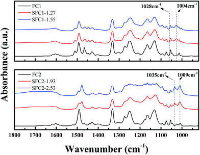
The post-sulfonation reaction was also substantiated from the FTIR spectra, as shown in Fig. 3. The absorption peaks at around 1463 and 1492 cm−1 are assigned to the phenyl ring, and the peak at 1603 cm−1 is assigned to the C![[double bond, length as m-dash]](https://www.rsc.org/images/entities/char_e001.gif) C stretching vibrations. Characteristic band at 1004 cm−1 was attributed to the in-plane bending vibration of a sulfonic acid group substituted at a phenyl ring, and the peaks at 1028–1035 cm−1 were assigned to the symmetric stretching of the O
C stretching vibrations. Characteristic band at 1004 cm−1 was attributed to the in-plane bending vibration of a sulfonic acid group substituted at a phenyl ring, and the peaks at 1028–1035 cm−1 were assigned to the symmetric stretching of the O![[double bond, length as m-dash]](https://www.rsc.org/images/entities/char_e001.gif) S
S![[double bond, length as m-dash]](https://www.rsc.org/images/entities/char_e001.gif) O group.16,28,29
O group.16,28,29
Thermal stability
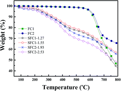
Thermogravimetric analysis curves are shown in Fig. 4, and the 5% weight loss temperatures (Td 5%) for sulfonated polymers are extracted in Table 1. The unsulfonated polymers FC1 and FC2 demonstrated excellent thermal stability with 5% weight loss temperatures of 598 °C and 605 °C, respectively. All the sulfonated polymers exhibited a similar trend, which consisted of three degradation steps. An initial weight loss before 200 °C was related to the removal of hydrated water and solvent. The secondary degradation curve observed at around 200–400 °C was attributed to the decomposition of sulfonic acid groups. The last step occurring above 450 °C consists of the degradation of the remaining polymer main chain.Mechanical properties
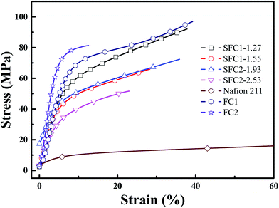
The mechanical properties of the SFC series (acid form) membranes were measured as shown in Fig. 5 and are listed in Table 1. Tensile strength (51–92 MPa) and Young's modulus (0.65–0.88 GPa) were much higher than those of the Nafion 211 membrane (26 MPa and 0.10 MPa, respectively). However, the SFC membranes exhibited much lower elongations at break (24 to 38%) because of the presence of bulky and rigid multi-phenylated backbone structures as compared to the soft liner perfluorocarbons structure of Nafion 211 membrane (146%). This result was very similar with that of other sulfonated aromatic hydrocarbon polymers reported in previous literatures.30–32Water uptake, dimensional stability, and oxidative stability
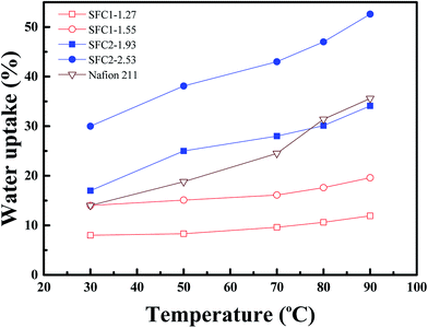
The water uptake of PEMs plays an important role in evaluating the proton conductivity because water molecules are proton transportation carriers in the PEMs. However, excessive water uptake may prompt improper dimensional changes and loss of the mechanical durability. The water uptake (Fig. 6) and dimensional stability of the SFC series membranes were investigated, and the results are listed in Table 2. As expected, the water uptake of the membranes increased with an increase in temperature and IEC value. Water uptake of the SFC1 series membranes is in the range from 8 to 14% at 30 °C, whereas it is in the range of 10.6–17.6% at 80 °C. Compared to Nafion 211, SFC2-1.93 exhibited an approximate water uptake in all temperature ranges (around 30% at 80 °C). SFC2-2.53 demonstrated highest water uptake (47.3%), which was larger than that of Nafion 211. Due to increased hydrophilicity, higher IEC membranes are able to absorb more water.| Membrane | IECa (mmol g−1) | Water uptake (%) | ΔLb (%) | ΔTb (%) | |||
|---|---|---|---|---|---|---|---|
| 30 °C | 80 °C | 30 °C | 80 °C | 30 °C | 80 °C | ||
| a IEC determined by acid–base titration.b Change in film length (ΔL) and thickness (ΔT). | |||||||
| SFC1-1.27 | 1.27 | 8.0 | 10.6 | 1.0 | 3.1 | 13.0 | 17.0 |
| SFC1-1.55 | 1.55 | 14.0 | 17.6 | 2.0 | 6.0 | 14.5 | 28.6 |
| SFC2-1.93 | 1.93 | 17.0 | 30.1 | 7.5 | 10.0 | 19.3 | 24.0 |
| SFC2-2.53 | 2.53 | 30.2 | 47.3 | 23.0 | 27.8 | 31.3 | 56.5 |
| Nafion 211 | 0.91 | 14.0 | 31.4 | 0.09 | 0.15 | 13.2 | 20.1 |
The swelling of the SFC1 series membranes caused less than 5.7% change in the length and 28.6% change in the thickness at 80 °C because of lower degree of sulfonation. SFC2-1.93 showed an excellent dimensional stability with 10% change in length and 24% change in thickness at 80 °C. The SFC2-2.53 with the highest IEC exhibited the highest water uptake ability but was also accompanied by largest dimensional changes (ΔL = 27.8% and ΔT = 56.5% at 80 °C). However, the SFC2 series showed a higher IEC value and retained an appropriate swelling ratio compared to the SFC1 series and Nafion 211. This result may be attributed to the high free volume and rigidity of the tetraphenylated structure, which allowed water occupancy and was able to maintain acceptable swelling ratio of the membranes.17,33,34
It is known that the oxidative radicals such as HO˙ and HOO˙ originate from excess oxygen during the fuel cell operation. In order to evaluate the oxidative stability, the membranes were soaked in Fenton's reagent, a highly oxidative reagent.35 Oxidative stability of the SFC membranes was examined by observing the weight loss after treatment with the Fenton's reagent. All the membranes exhibited excellent oxidative stability, as shown in Table 3. The weight loss of the membranes was less than 3% after treatment with the Fenton's reagent at 80 °C for 1 h. After 22 h, very small fragments of SFC1-1.55 and SFC2-2.53 were found. However, the membranes still remained insoluble in Fenton's reagent after 24 h of treatment at 80 °C, which showed similar or higher stability than other reported polymers.11,32,36,37 Due to their fully aromatic structure, the polymers demonstrated high oxidative stability. Furthermore, previous literature indicated that the presence of trifluoromethyl substituents in the polymer is effective for the formation of an electron deficient structure, which can improve the oxidative stability of a PEM.31,38 The hydrolytic stability of the membranes was examined by immersing them in water at 140 °C for 24 h, and the results are listed in Table 3. All the membranes exhibited excellent hydrolytic stability with weight loss lower than 1%.
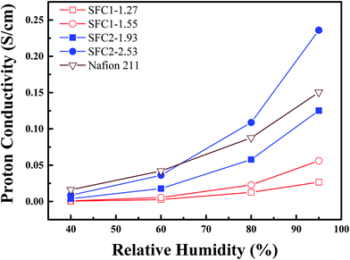
| Sulfonated polymer | Proton conductivity (80 °C) (S cm−1) | Oxidative stabilityc | Hydrolytic stabilityc | ||||
|---|---|---|---|---|---|---|---|
| 40% | 60% | 80% | 95% | RW1a | RW2b | ||
| a Residual weight (%) of membranes after heating in Fenton's reagent at 80 °C for 1 h.b Residual weight (%) of membranes after heating in Fenton's reagent at 80 °C for 24 h.c After heating in water at 140 °C for 24 h. | |||||||
| SFC1-1.27 | 0.00 | 0.00 | 0.01 | 0.03 | 99 | 93 | 100 |
| SFC1-1.55 | 0.00 | 0.01 | 0.02 | 0.06 | 98 | 64 | 99 |
| SFC2-1.93 | 0.00 | 0.02 | 0.06 | 0.13 | 98 | 78 | 99 |
| SFC2-2.53 | 0.01 | 0.04 | 0.11 | 0.24 | 97 | 50 | 99 |
| Nafion 211 | 0.02 | 0.04 | 0.09 | 0.15 | 98 | 88 | 99 |
Proton conductivity
The proton conductivities of the SFC series membranes were measured at 80 °C with the increasing relative humidity, as shown in Fig. 7, and that of Nafion 211 was also measured under the same conditions, as a reference. All the SFC membranes exhibited a dependence of the proton conductivity on the relative humidity. The SFC1 series membranes showed lower conductivities than Nafion 211, with the highest conductivity being 0.06 mS cm−1 (SFC1-1.55) at 95% RH. For comparison, the highest conductivity for Nafion 211 was 0.15 S cm−1 at the same condition. The SFC2 series membranes showed a similar increasing trend as Nafion 211 under increasing RH. SFC2-1.93 exhibited the same conductivity from 0.02 to 0.13 S cm−1 (60% to 95% RH). As compared to Nafion 211, SFC2-2.53 demonstrated a comparable conductivity from 40 to 60% RH that was able to transcend when RH was greater than 65% and reached 0.24 S cm−1 under fully hydrated states (95% RH). Table 3 displays the proton conductivities of the SFC series membranes.Microstructure analysis
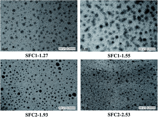
The microstructure of the SFC series membranes was investigated by TEM, as shown in Fig. 8. In the images, the dark areas represent the hydrophilic (sulfonate groups) domain and the brighter areas represent the hydrophobic (polymer backbones) domain. As presented in the images, excellent well-dispersed hydrophilic/hydrophobic phase separation was observed throughout the membrane in all the cases. The microstructures of SFC1-1.27 and SFC1-1.55 exhibited clearly spherical ionic clusters of around 2–8 nm and 5–10 nm diameter, respectively. The diameter of the ionic clusters of the SFC1 series membranes slightly increased with the increasing IEC value. SFC2 series membranes also displayed clearly spherical ionic clusters. SFC2-1.93 exhibited small amount of particle aggregation and loose ionic clusters (ca. 2–15 nm). The membrane with the highest IEC value, SFC2-2.53, was the most dense and had a uniform size (ca. 2–4 nm) with slightly interconnected ionic clusters, very similar to Nafion 211.39 The small and numerous sulfonic acid clusters could contribute to the formation of narrow and well-connected proton channels.40 This may explain why SFC2-2.53 achieved highest proton conductivity and was accompanied with higher water uptake and dimensional changes.Fuel cell performance
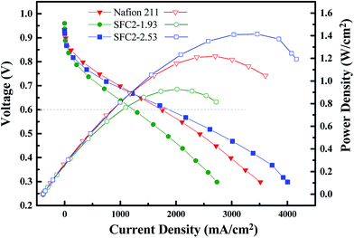
Preliminary H2/O2 fuel cell performance of SFC2-1.93 (30 μm), SFC2-2.53 (17 μm), and Nafion 211 (25 μm) was examined at 80 °C under fully hydrated conditions (100% RH). As shown in Fig. 9, both the SFC2-1.93 and SFC2-2.53 membranes demonstrated good performance and had comparable power density to that of N211. The SFC2-1.93 membrane exhibited good performance (current density of over 1200 mA cm−2 at 0.6 V) but greater ohmic region loss than Nafion 211, despite the thicker membranes, which increased interfacial resistance between the Nafion electrode and the hydrocarbon membrane. However, SFC2-2.53 exhibited an excellent current density of over 1800 mA cm−2 at 0.6 V and performed much better than SFC2-1.93 and Nafion 211 in the ohmic regions, possibly due to the higher proton conductivity of SFC2-2.53 observed ex situ and employment of thinner membranes. The maximum power densities of SFC2-1.93 and SFC2-2.53 are 0.93 and 1.41 W cm−2, respectively, under full humidification, promising preliminary results as compared to 1.22 W cm−2 for the Nafion 211 reference MEA with fully compatible electrodes and highly optimized catalyst and ionomer loadings, hydration state, and gas diffusion layers. The high cell performance of the SFC2-2.53 membrane is possibly due to the good dimensional stability. It is important that the in-plane swelling is restricted to prevent the delamination of the catalyst layer occurring from a dimensional mismatch between the electrode and membranes.Conclusion
In summary, we introduced a series of novel sulfonated poly(arylene ether)s containing a tetra-trifluoromethyl-substituted multi-phenyl structure. The polymers were prepared via polycondensation, and post-sulfonation was processed by chlorosulfonic acid. All the membranes showed high thermal stability, good dimensional stability, excellent oxidative stability, and suitable hydrophilic/hydrophobic microphase separation. Among the membranes, SFC2-2.53 exhibited high proton conductivity of 0.24 S cm−1 under fully hydrated conditions. Furthermore, the fuel cell test of the SFC2-2.53 membrane demonstrated an excellent performance with the current density of over 1800 mA cm−2 at 0.6 V and the maximum power density reached 1.41 W cm−2 at 80 °C under fully hydrated conditions, which were superior than those of Nafion 211. The combination of high thermal stability, acceptable dimensional stability, high proton conductivity, and excellent single cell performance makes SFC2-2.53 attractive as a PEM material for fuel cells applications.Acknowledgements
The authors are grateful to the Ministry of Science and Technology, Taiwan (MOST 105-2221-E-110-090-) for the financial support of this work. We also gratefully acknowledge Y. Y. Chuang at the Fuel Cell Center of the Yuan Ze University for the TEM measurements.References
- B. C. H. Steele and A. Heinzel, Nature, 2001, 414, 345–352 CrossRef CAS PubMed.
- H. Zhang and P. K. Shen, Chem. Soc. Rev., 2012, 41, 2382–2394 RSC.
- A. Kraytsberg and Y. Ein-Eli, Energy Fuels, 2014, 28, 7303–7330 CrossRef CAS.
- H. Zhang and P. K. Shen, Chem. Rev., 2012, 112, 2780–2832 CrossRef CAS PubMed.
- K. Miyatake, D. Hirayama, B. Bae and M. Watanabe, Polym. Chem., 2012, 3, 2517 RSC.
- J. Rozière and D. J. Jones, Annu. Rev. Mater. Res., 2003, 33, 503–555 CrossRef.
- H. Jang, S. Sutradhar, J. Yoo, J. Ha, J. Pyo, C. Lee, T. Ryu and W. Kim, Energies, 2016, 9, 115 CrossRef.
- O. Danyliv, C. Iojoiu, S. Lyonnard, N. Sergent, E. Planes and J.-Y. Sanchez, Macromolecules, 2016, 49, 4164–4177 CrossRef CAS.
- B. Wang, L. Hong, Y. Li, L. Zhao, Y. Wei, C. Zhao and H. Na, ACS Appl. Mater. Interfaces, 2016, 8, 24079–24088 CAS.
- Y. Zhang, J. Li, L. Ma, W. Cai and H. Cheng, Energy Technol., 2015, 3, 675–691 CrossRef CAS.
- D. W. Shin, S. Y. Lee, N. R. Kang, K. H. Lee, M. D. Guiver and Y. M. Lee, Macromolecules, 2013, 46, 3452–3460 CrossRef CAS.
- M. A. Hickner, H. Ghassemi, Y. S. Kim, B. R. Einsla and J. E. McGrath, Chem. Rev., 2004, 104, 4587 CrossRef CAS PubMed.
- B. Liu, G. P. Robertson, D.-S. Kim, M. D. Guiver, W. Hu and Z. Jiang, Macromolecules, 2007, 40, 1934–1944 CrossRef CAS.
- Y. Chang, G. F. Brunello, J. Fuller, M. Hawley, Y. S. Kim, M. Disabb-Miller, M. A. Hickner, S. S. Jang and C. Bae, Macromolecules, 2011, 44, 8458–8469 CrossRef CAS.
- Y. C. Huang, R. H. Tai, H. F. Lee, P. H. Wang, R. Gopal, C. C. Lee, M. Y. Chang and W. Y. Huang, Int. J. Polym. Sci., 2016, 2016, 1–8 Search PubMed.
- H. F. Lee, P. H. Wang, Y. C. Huang, W. H. Su, R. Gopal, C. C. Lee, S. Holdcroft and W. Y. Huang, J. Polym. Sci., Part A: Polym. Chem., 2014, 52, 2579–2587 CrossRef CAS.
- H. F. Lee, Y. C. Huang, P. H. Wang, C. C. Lee, Y. S. Hung, R. Gopal, S. Holdcroft and W. Y. Huang, Mater. Today Commun., 2015, 3, 114–121 CrossRef CAS.
- T. J. Skalski, B. Britton, T. J. Peckham and S. Holdcroft, J. Am. Chem. Soc., 2015, 137, 12223–12226 CrossRef CAS PubMed.
- Y. D. Lim, D. W. Seo, S. H. Lee, M. A. Hossain, K. Kang, H. Ju and W. G. Kim, Int. J. Hydrogen Energy, 2013, 38, 631–639 CrossRef CAS.
- H. Wei, R. Chen and G. Li, Int. J. Hydrogen Energy, 2015, 40, 14392–14397 CrossRef CAS.
- S. Saha, R. Mukherjee, A. Singh and S. Banerjee, Polym. Eng. Sci., 2017, 57, 312–323 CAS.
- D. S. Kim, G. P. Robertson, Y. S. Kim and M. D. Guiver, Macromolecules, 2009, 42, 957–963 CrossRef CAS.
- H. C. Lee, H. S. Hong, Y.-M. Kim, S. H. Choi, M. Z. Hong, H. S. Lee and K. Kim, Electrochim. Acta, 2004, 49, 2315–2323 CrossRef CAS.
- W. Y. Huang and S. Y. Huang, Macromolecules, 2010, 43, 10355–10365 CrossRef CAS.
- D. J. Jones, B. Purushothaman, S. Ji, A. B. Holmes and W. W. Wong, Chem. Commun., 2012, 48, 8066–8068 RSC.
- S. Banerjee, G. Maier, A. Salunke and M. Madhra, J. Appl. Polym. Sci., 2001, 82, 3149–3156 CrossRef CAS.
- A. K. Mohanty, E. A. Mistri, S. Banerjee, H. Komber and B. Voit, Ind. Eng. Chem. Res., 2013, 52, 2772–2783 CrossRef CAS.
- B.-K. Chen, J.-M. Wong, T.-Y. Wu, L.-C. Chen and I. C. Shih, Polymers, 2014, 6, 2720–2736 CrossRef.
- X. Wang, H. Zhang and S. C. Jana, J. Mater. Chem. A, 2013, 1, 13989 CAS.
- R. Mukherjee, S. Banerjee, H. Komber and B. Voit, J. Membr. Sci., 2016, 510, 497–509 CrossRef CAS.
- A. K. Mohanty, E. A. Mistri, A. Ghosh and S. Banerjee, J. Membr. Sci., 2012, 409–410, 145–155 CrossRef CAS.
- L. Chen, S. Zhang, Y. Jiang and X. Jian, RSC Adv., 2016, 6, 75328–75335 RSC.
- S. Lee, J. Ann, H. Lee, J.-H. Kim, C.-S. Kim, T.-H. Yang and B. Bae, J. Mater. Chem. A, 2015, 3, 1833–1836 CAS.
- Y. Gao, G. P. Robertson, D.-S. Kim, M. D. Guiver, S. D. Mikhailenko, X. Li and S. Kaliaguine, Macromolecules, 2007, 40, 1512–1520 CrossRef CAS.
- J. H. Liao, Q. F. Li, H. C. Rudbeck, J. O. Jensen, A. Chromik, N. J. Bjerrum, J. Kerres and W. Xing, Fuel Cells, 2011, 11, 745–755 CrossRef CAS.
- A. Singh, S. Banerjee, H. Komber and B. Voit, RSC Adv., 2016, 6, 13478–13489 RSC.
- S. G. Jo, T.-H. Kim, S. J. Yoon, S.-G. Oh, M. S. Cha, H. Y. Shin, J. M. Ahn, J. Y. Lee and Y. T. Hong, J. Membr. Sci., 2016, 510, 326–337 CrossRef CAS.
- R. Mukherjee, A. K. Mohanty, S. Banerjee, H. Komber and B. Voit, J. Membr. Sci., 2013, 435, 145–154 CrossRef CAS.
- J. Peron, A. Mani, X. Zhao, D. Edwards, M. Adachi, T. Soboleva, Z. Shi, Z. Xie, T. Navessin and S. Holdcroft, J. Membr. Sci., 2010, 356, 44–51 CrossRef CAS.
- C. Fang, X. N. Toh, Q. Yao, D. Julius, L. Hong and J. Y. Lee, J. Power Sources, 2013, 226, 289–298 CrossRef CAS.
Footnote |
| † Electronic supplementary information (ESI) available. See DOI: 10.1039/c7ra04731b |
| This journal is © The Royal Society of Chemistry 2017 |

