 Open Access Article
Creative Commons Attribution 3.0 Unported Licence
Simultaneous enhancements in stability and CO tolerance of Pt electrocatalyst by double poly(vinyl pyrrolidone) coatings†
Jiuxiao Sun‡
a,
Ying Ling‡b,
Quan Zhangb,
Xinxin Yub and
Zehui Yang *b
*b
aCollege of Materials Science and Engineering, Wuhan Textile University, Fangzhi RD, Wuhan, 430200, China
bSustainable Energy Laboratory, Faculty of Materials Science and Chemistry, China University of Geosciences Wuhan, 388 Lumo RD, Wuhan, 430074, China. E-mail: yeungzehui@gmail.com
First published on 8th June 2017
Abstract
CO poisoning and low durability of the anodic electrocatalyst is one of the obstacles restricting the practical application of direct methanol fuel cells (DMFCs). In this work, a highly CO-tolerant and durable platinum (Pt) electrocatalyst is fabricated by introducing double poly(vinyl pyrrolidone) (PVP) layers into the electrocatalyst, in which the first PVP layer is utilized to coat carbon black before Pt deposition and the second PVP layer is laid on the Pt nanoparticles. The first PVP layer on carbon black is favorable for higher Pt utilization efficiency attributed to the capping of micropores on carbon black. The second PVP layer on the Pt nanoparticles facilitates the removal of adsorbed CO species on the Pt nanoparticles and suppresses the Pt aggregation; meanwhile, the PVP layer on the Pt nanoparticles showed a negligible effect (7%) on the electrochemical surface area (ECSA) and methanol oxidation reaction (MOR). Thus, double PVP layers coated Pt electrocatalyst is potentially utilizable for real DMFC operation.
Introduction
Sustainable energy technologies (fuel cells, solar cells, lithium-ion/sulfur batteries) have attracted much attention due to their cleanness and sustainability.1–3 The polymer electrolyte fuel cell (PEFC) is one of the most-researched systems for electrochemical energy production. Based on the difference in fuel, PEFC is classified as hydrogen PEFC or direct methanol fuel cell (DMFC). DMFC is a promising alternative energy source for portable devices due to its easy storage and high energy density (5.04 kW h L−1).4,5 However, its commercialization is still blocked due to three serious problems at the anode side: (i) low durability of the electrocatalyst; (ii) carbon monoxide (CO) poisoning caused by incomplete methanol oxidation; (iii) sluggish methanol oxidation reaction (MOR).6–8Alloying ruthenium (Ru) with Pt is proved as an efficient method to enhance the CO tolerance of electrocatalyst due to the easy formation of Ru(OH)ads species (Ru + H2O → Ru(OH)ads + H+ + e−) under lower potential compared to Pt(OH)ads.9 However, the alloying method sacrifices MOR activity and durability of the electrocatalyst since Ru has lower MOR activity and is dissolvable in acidic medium.10,11 Thus, development of Pt electrocatalyst with considerable CO tolerance is desirable for DMFC.12–15 Pt deposited on carbon nanomaterials were numerously studied as electrocatalysts toward methanol oxidation reaction.16–19 Xing20 and Li et al.21 reported that phosphorus facilitated the removal of adsorbed CO species from Pt nanoparticle because phosphorus could weaken the binding energy between Pt and CO. Doping carbon nanotubes with boron was also reported an efficient method to promote the CO oxidation by Pt nanoparticles;22 while, doping with phosphorus and boron suffers complicated process and the CO tolerance was highly depended on doping amount. Coating Pt nanoparticles with polybenzimidazole (PBI),23 polyaniline (PANI),24 were numerously reported since these polymers fastened the formation of Pt(OH)ads species by nitrogen atoms. Also, we have reported that poly(vinylphosphonic acid) (PVPA) coated Pt electrocatalyst exhibited an enhanced CO tolerance due to the presence of phosphorus in PVPA.25–28 Meanwhile, we found that poly(vinyl pyrrolidone) (PVP) could be homogeneously coated on Pt nanoparticles with the assistance of PBI due to the hydrogen bonding and PVP coated electrocatalyst showed enhancement in CO tolerance and durability of Pt electrocatalyst because PVP facilitated the water adsorption resulting in formation of Pt(OH)ads species (Pt + H2O → Pt(OH)ads + H+ + e−), which consumes Pt(CO)ads species.29
Based on above consideration, here, we reported a Pt electrocatalyst with double PVP polymer layers as schematically shown in Fig. 1, in which the first PVP layer was homogeneously coated on carbon black (CB) similar to carbon nanotubes (CNT) as reported by us30 and the second PVP layer was coated on Pt nanoparticles due to the hydrogen bonding between polymer chains of PVP. Due to the presence of PVP, the CO tolerance would be enhanced and growth of Pt nanoparticle also would be suppressed due to the sandwich structure. The importance of two PVP layers was systematically studied by durability test, methanol oxidation reaction (MOR) and CO stripping voltammetry. Compared to our previous reports,25,27,29 in this work, we utilized two PVP polymer layers for fabrication of electrocatalyst and the Pt stability and CO tolerance were simultaneously enhanced.
Experimental
Materials
Methanol, H2SO4, isopropanol, N,N-dimethylformamide (DMF), hydrogen hexachloroplatinate hexahydrate (H2PtCl6·6H2O), ethylene glycol (EG) and poly(vinylpyrrolidone) (PVP, K30) were purchased from Sinopharm Chemical Reagent Co., Ltd. Commercial CB/Pt (Pt: 40 wt%) and were purchased from Alfa Aesar. Nafion solution (5 wt%) were purchased from Sigma-Aldrich. Aqueous solutions were prepared using Milli-Q water and all chemicals were used as received without further purification.Synthesis of CB/PVP/Pt/PVP
The CB/PVP/Pt was synthesized according to our previous reports.30 Briefly, 20 mg of CB was wrapped by PVP (10 mg) using sonication for 1 h in water. The composite was collected by filtration, washing and drying under vacuum at 80 °C. 20 mg of CB/PVP was dispersed in EG aq. (v/v = 3![[thin space (1/6-em)]](https://www.rsc.org/images/entities/char_2009.gif) :
:![[thin space (1/6-em)]](https://www.rsc.org/images/entities/char_2009.gif) 2). The Pt loading was carried out by reduction of H2PtCl6·6H2O (17.7 mg) at 140 °C for 6 h under argon atmosphere. The resultant solution was filtered, washed, and dried overnight under vacuum at 80 °C to completely remove solvent. 20 mg of CB/PVP/Pt was dispersed in 20 mL of water by sonication for 10 min to which 10 mg of the PVP was added, then ultra-sonicated for 1 h followed by filtration using a 0.2 μm PTFE filter paper to collect the product, which was washed several times with Milli-Q water to remove free PVP, then dried overnight at 80 °C under vacuum to remove any residual solvent.
2). The Pt loading was carried out by reduction of H2PtCl6·6H2O (17.7 mg) at 140 °C for 6 h under argon atmosphere. The resultant solution was filtered, washed, and dried overnight under vacuum at 80 °C to completely remove solvent. 20 mg of CB/PVP/Pt was dispersed in 20 mL of water by sonication for 10 min to which 10 mg of the PVP was added, then ultra-sonicated for 1 h followed by filtration using a 0.2 μm PTFE filter paper to collect the product, which was washed several times with Milli-Q water to remove free PVP, then dried overnight at 80 °C under vacuum to remove any residual solvent.
Material characterization
X-ray photoelectron spectroscopy (XPS) was carried out using a ThermoScientific K-Alpha instrument. The pressure in the XPS analysis chamber was kept below 10−9 Pa during the measurements. During the calibration process, the binding energy (BE) of C1s peak was fixed at 284.5 eV as standard. Thermogravimetric analysis (TGA) was conducted using a TGA analyzer (NETZSCH5) at the heating rate of 10 °C min−1 and 100 mL min−1 oxygen-flow. The TEM micrographs were measured using JEM-2010 (JEOL, acceleration voltage of 120 kV) electron microscope.Electrochemical measurements
The electrochemical measurements were performed using a glassy carbon electrode (GCE) with a conventional three-electrode system in a vessel at 25 °C. GCE with a geometric surface area of 0.126 cm2 was used as the working electrode. Pt wire and Ag/AgCl were used as the counter and reference electrodes, respectively. The potential of the electrode was controlled by CHi604e potentiostat. The electrocatalyst ink was prepared as follows. The electrocatalyst (1.0 mg) was ultrasonically dispersed in 80% isopropanol aq. (v/v = 4![[thin space (1/6-em)]](https://www.rsc.org/images/entities/char_2009.gif) :
:![[thin space (1/6-em)]](https://www.rsc.org/images/entities/char_2009.gif) 1, 2.0 mL) to form homogeneous suspension, which was casted on GCE and the loading amount of Pt was controlled at 14 μg cm−2, then air-dried. Cyclic voltammetry (CV) measurement was carried at the scan rate of 50 mV s−1 in N2-saturated 0.5 M H2SO4 electrolyte after activation of the electrocatalyst and electrochemical surface area (ECSA) value was determined from CV curves. All the potentials were referenced to the reference hydrogen electrode (RHE).
1, 2.0 mL) to form homogeneous suspension, which was casted on GCE and the loading amount of Pt was controlled at 14 μg cm−2, then air-dried. Cyclic voltammetry (CV) measurement was carried at the scan rate of 50 mV s−1 in N2-saturated 0.5 M H2SO4 electrolyte after activation of the electrocatalyst and electrochemical surface area (ECSA) value was determined from CV curves. All the potentials were referenced to the reference hydrogen electrode (RHE).
Methanol oxidation reaction (MOR)
The MOR was evaluated in N2-saturated 0.5 M H2SO4 and 1 M or 2 M methanol at 25 °C with the scan rate of 50 mV s−1.Pt stability test
The Pt stability was tested using the protocol of the Fuel Cell Commercialization Conference of Japan (FCCJ) (measured in N2-saturated 0.5 M H2SO4 at 25 °C), in which the potential was kept at 0.6 V vs. RHE for 3 s, then applied up to 1 V vs. RHE for another 3 s. The procedure was cycled, and the CV measurement was carried out after every 600 cycles (see ESI, Fig. S1†).31Results and discussion
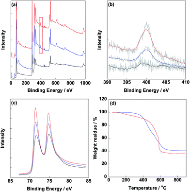
After synthesis of electrocatalysts, XPS was carried out to determine the typical elements as shown in Fig. 2. From Fig. 2b, obvious N1s peaks were observed at 400 eV for CB/PVP/Pt and CB/PVP/Pt/PVP derived from PVP. Meanwhile, intensity of N1s peak of CB/PVP/Pt/PVP was higher compared to that of CB/PVP/Pt due to the additional PVP layer on Pt nanoparticles. N1s peak located at 400 eV was ascribed to the pyrrolic nitrogen. Pt4f peaks (Pt4f7/2 and Pt4f5/2) were clearly detected at 75.0 eV (Fig. 2c) for three electrocatalysts and intensity of Pt4f peak of CB/PVP/Pt/PVP was lower with relative to that of CB/PVP/Pt due to the coverage of PVP layer on Pt nanoparticles. The XPS results suggested that PVP layer was successfully covered on Pt nanoparticles. Pt amounts in electrocatalysts were measured by TGA as shown in Fig. 2d. After heating to 900 °C under air atmosphere, Pt contents in CB/PVP/Pt and CB/PVP/Pt/PVP were estimated as 40.6 wt% and 36.1 wt%, respectively. It should be noted that the remained solid was Pt oxide after heating to 900 °C, while, oxygen atoms showed almost negligible effect on Pt content, thus, the Pt content in electrocatalyst was roughly determined by the weight residue. The decrease in Pt content was due to the second PVP layer on Pt nanoparticles, which was calculated to be 11.1 wt%. From TEM images shown in Fig. 3, Pt nanoparticles were homogeneously deposited on CB/PVP with diameters of 2.8 ± 0.2 nm and 2.9 ± 0.3 nm for CB/PVP/Pt and CB/PVP/Pt/PVP, respectively. Commercial CB/Pt was used as control sample with Pt diameter of 3.3 ± 0.3 nm (for histogram, see Fig. S2†).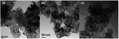 | ||
| Fig. 3 TEM images of commercial CB/Pt (a), CB/PVP/Pt (b) and CB/PVP/Pt/PVP (c) electrocatalysts before durability test. | ||
In order to study the effect of two PVP layers in electrocatalysts, electrochemical analysis was tested in N2-saturated 0.5 M H2SO4 electrolyte. Electrochemical surface area is calculated based on the following equation from hydrogen adsorption peak of CV curve:
| ECSA = QH/(210 × Pt amount loaded on electrode) | (1) |
| Theoretical surface area = 6/ρd | (2) |
| Pt utilization efficiency = ECSA/TSA | (3) |
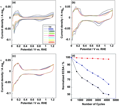
Commercial CB/Pt was used for comparison with ECSA of 71.1 m2 gPt−1 as shown in Fig. 4a. ECSA of CB/PVP/Pt was 95.2 m2 gPt−1 (Fig. 4b), which was higher compared to that of commercial CB/Pt due to the first coating of PVP on carbon black. As well known, some Pt nanoparticles were deposited into the micropores on carbon black and unable to be used during electrochemical measurement;34 while, coating carbon black with PVP capped these micropores and all the Pt nanoparticles were able to be used resulting in higher Pt utilization efficiency (95%) calculated from eqn (2) and (3). In contrast, Pt utilization efficiency was 84% for commercial CB/Pt. Thus, the first coating of PVP induced a higher Pt utilization efficiency of electrocatalyst. ECSA of CB/PVP/Pt/PVP decreased to 89.5 m2 gPt−1 (Fig. 4c) due to the second coating of PVP layer on Pt nanoparticles, which blocked some active sites of Pt nanoparticles resulting in lowering Pt utilization efficiency (93%). However, CB/PVP/Pt/PVP showed stable CV curves during the potential cycles and remained almost 100% of ECSA after durability test. In contrast, ECSA retention of CB/PVP/Pt was only 65%. The second coating of PVP was essential to enhance the durability of electrocatalyst since Pt migration and aggregation were suppressed during the potential cycling. After durability test, the morphology changes were checked by TEM as shown in Fig. 5. From Fig. 5(a and b), Pt sizes were grown to 5.4 ± 0.5 nm and 4.3 ± 0.5 nm for commercial CB/Pt and CB/PVP/Pt, respectively (for histogram, see Fig. S3†); while, the Pt size were almost stable (3.1 ± 0.2 nm, Fig. 5c) for CB/PVP/Pt/PVP, which was the strong evidence for suppression of Pt aggregation by two PVP coatings. Thus, the second PVP layer on Pt nanoparticles was of importance for enhancement in durability.
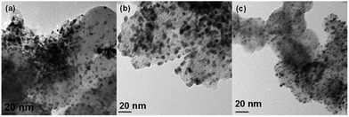 | ||
| Fig. 5 TEM images of commercial CB/Pt (a), CB/PVP/Pt (b) and CB/PVP/Pt/PVP (c) electrocatalysts after durability test. | ||
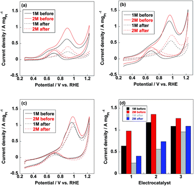
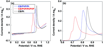
Methanol oxidation reaction (MOR) is the anodic reaction for DMFC and carbon monoxide (CO) generates during the incomplete oxidation of methanol, which is poisoning for Pt nanoparticles. The CO anti-poisoning (CO tolerance) could be estimated from the ratio of If and Ib peak values, which represent anodic and reverse anodic peaks, respectively. Higher If/Ib ratio is indicative of higher CO tolerance since Pt(CO)ads is generated in If peak and reduces to pure Pt in Ib peak.35–37 As shown in Fig. 6, If and Ib peaks were clearly observed from three electrocatalysts and related If/Ib ratios were displayed in Table 1. Compared to commercial CB/Pt, If/Ib ratio was increased to 4.7 after introducing PVP to electrocatalyst. If/Ib ratio of CB/PVP/Pt/PVP reached 8.6 and 8.0 measured in 1 M and 2 M methanol, respectively. The enhanced If/Ib ratio suggested that two PVP layers in electrocatalyst were of significant importance to eliminate CO poisoning problem. After durability test, If/Ib ratios of commercial CB/Pt sharply decreased to 1.3; while, CB/PVP/Pt/PVP showed only 10% degradation in If/Ib ratio due to the stabilization of PVP in electrocatalysts since PVP accelerated the adsorption of H2O resulting in formation of Pt(OH)ads species, which reacts with Pt(CO)ads species to pure Pt. After durability test, CO tolerance of CB/PVP/Pt/PVP was 6 and 2 times higher compared to that of commercial CB/Pt and CB/PVP/Pt. The CO tolerance was also confirmed by CO stripping voltammetry as shown in Fig. 7. From Fig. 7b, CO oxidation peak negatively shifted after coating with PVP, indicating that PVP facilitated the removal of adsorbed CO species on Pt nanoparticles. The mass activities of electrocatalysts before and after durability test were shown in Fig. 6d. Mass activities of CB/PVP/Pt (1.2 A mgPt−1 and 1.4 A mgPt−1) was 2 and 1.4 times higher compared to commercial CB/Pt (0.64 A mgPt−1 and 1.0 A mgPt−1), which was ascribed to the higher Pt utilization efficiency triggered by PVP layer. Mass activity decreased by only 7% after further coating with PVP on Pt nanoparticles indicating that methanol could penetrate PVP layer and PVP layer showed negligible effect on MOR. Both of commercial CB/Pt and CB/PVP/Pt lost 50% mass activities after durability test. In sharp contrast, the mass activity was lost only 12% for CB/PVP/Pt/PVP due to the higher durability. Thus, the first PVP layer on carbon black improved the Pt utilization efficiency and the second layer promoted CO tolerance and Pt stability.
| Electrocatalyst | If/Ib (1 M, before) | If/Ib (2 M, before) | If/Ib (1 M, after) | If/Ib (2 M, after) |
|---|---|---|---|---|
| CB/Pt | 3.4 | 3.2 | 1.3 | 1.3 |
| CB/PVP/Pt | 4.7 | 3.9 | 3.1 | 2.5 |
| CB/PVP/Pt/PVP | 8.6 | 8.0 | 7.7 | 7.3 |
Conclusions
In conclusion, we have successfully introduced two PVP layers into the fabrication of Pt electrocatalyst, in which carbon black was coated with PVP layer and second PVP layer was laid on Pt nanoparticles. We found that the first layer on carbon black was essential to enhance the Pt utilization efficiency as well as methanol oxidation; the second layer on Pt nanoparticles improved the Pt stability and CO tolerance of electrocatalyst. The CO tolerance and mass activity measured in MOR of CB/PVP/Pt/PVP were almost stable during the durability test, imply that CB/PVP/Pt/PVP is a promising anodic electrocatalyst for DMFC and could be applicable in real DMFC operation.Acknowledgements
The Project was supported by the Fundamental Research Funds for the Central Universities, China University of Geosciences (Wuhan) (CUG170615).Notes and references
- M. Winter and R. J. Brodd, Chem. Rev., 2004, 104, 4245–4270 CrossRef CAS PubMed.
- J. A. Asensio, E. M. Sanchez and P. Gomez-Romero, Chem. Soc. Rev., 2010, 39, 3210–3239 RSC.
- R. Borup, J. Meyers, B. Pivovar, Y. S. Kim, R. Mukundan, N. Garland, D. Myers, M. Wilson, F. Garzon, D. Wood, P. Zelenay, K. More, K. Stroh, T. Zawodzinski, J. Boncella, J. E. McGrath, M. Inaba, K. Miyatake, M. Hori, K. Ota, Z. Ogumi, S. Miyata, A. Nishikata, Z. Siroma, Y. Uchimoto, K. Yasuda, K.-i. Kimijima and N. Iwashita, Chem. Rev., 2007, 107, 3904–3951 CrossRef CAS PubMed.
- C. Koenigsmann and S. S. Wong, Energy Environ. Sci., 2011, 4, 1161–1176 CAS.
- X. Lai, J. E. Halpert and D. Wang, Energy Environ. Sci., 2012, 5, 5604–5618 CAS.
- H. Huang and X. Wang, J. Mater. Chem. A, 2014, 2, 6266–6291 CAS.
- H. Liu, C. Song, L. Zhang, J. Zhang, H. Wang and D. P. Wilkinson, J. Power Sources, 2006, 155, 95–110 CrossRef CAS.
- P. V. Samant, C. M. Rangel, M. H. Romero, J. B. Fernandes and J. L. Figueiredo, J. Power Sources, 2005, 151, 79–84 CrossRef CAS.
- J.-M. Léger, J. Appl. Electrochem., 2001, 31, 767–771 CrossRef.
- Z. Yang, X. Yu and F. Luo, RSC Adv., 2016, 6, 96416–96420 RSC.
- Z. Yang, X. Yu and Q. Zhang, RSC Adv., 2016, 6, 114014–114018 RSC.
- B. Jiang, C. Li, V. Malgras, M. Imura, S. Tominaka and Y. Yamauchi, Chem. Sci., 2016, 7, 1575–1581 RSC.
- V. Malgras, H. Ataee-Esfahani, H. Wang, B. Jiang, C. Li, K. C. W. Wu, J. H. Kim and Y. Yamauchi, Adv. Mater., 2016, 28, 993–1010 CrossRef CAS PubMed.
- Y. Li, B. P. Bastakoti, V. Malgras, C. Li, J. Tang, J. H. Kim and Y. Yamauchi, Angew. Chem., Int. Ed., 2015, 54, 11073–11077 CrossRef CAS PubMed.
- Y. Li, B. P. Bastakoti and Y. Yamauchi, APL Mater., 2016, 4, 040703 CrossRef.
- R.-X. Wang, J.-J. Fan, Y.-J. Fan, J.-P. Zhong, L. Wang, S.-G. Sun and X.-C. Shen, Nanoscale, 2014, 6, 14999–15007 RSC.
- R.-X. Wang, Y.-J. Fan, L. Wang, L.-N. Wu, S.-N. Sun and S.-G. Sun, J. Power Sources, 2015, 287, 341–348 CrossRef CAS.
- L. Wei, Y.-J. Fan, J.-H. Ma, L.-H. Tao, R.-X. Wang, J.-P. Zhong and H. Wang, J. Power Sources, 2013, 238, 157–164 CrossRef CAS.
- J.-P. Zhong, Y.-J. Fan, H. Wang, R.-X. Wang, L.-L. Fan, X.-C. Shen and Z.-J. Shi, J. Power Sources, 2013, 242, 208–215 CrossRef CAS.
- X. Xue, J. Ge, C. Liu, W. Xing and T. Lu, Electrochem. Commun., 2006, 8, 1280–1286 CrossRef CAS.
- L. X. Ding, A. L. Wang, G. R. Li, Z. Q. Liu, W. X. Zhao, C. Y. Su and Y. X. Tong, J. Am. Chem. Soc., 2012, 134, 5730–5733 CrossRef CAS PubMed.
- S. Wang, T. Cochell and A. Manthiram, Phys. Chem. Chem. Phys., 2012, 14, 13910–13913 RSC.
- T. Fujigaya, M. Okamoto, K. Matsumoto, K. Kaneko and N. Nakashima, ChemCatChem, 2013, 5, 1701–1704 CrossRef CAS.
- H. Gharibi, M. Amani, H. Pahlavanzadeh and M. Kazemeini, Electrochim. Acta, 2013, 97, 216–225 CrossRef CAS.
- Z. Yang, M. R. Berber and N. Nakashima, J. Mater. Chem. A, 2014, 2, 18875–18880 CAS.
- Z. Yang, I. H. Hafez, M. R. Berber and N. Nakashima, ChemCatChem, 2015, 7, 808–813 CrossRef CAS.
- Z. Yang, I. Moriguchi and N. Nakashima, ACS Appl. Mater. Interfaces, 2016, 8, 9030–9036 CAS.
- Z. Yang, C. Kim, S. Hirata, T. Fujigaya and N. Nakashima, ACS Appl. Mater. Interfaces, 2015, 7, 15885–15891 CAS.
- Z. Yang and N. Nakashima, ChemCatChem, 2016, 8, 600–606 CrossRef CAS.
- Z. Yang and N. Nakashima, J. Mater. Chem. A, 2015, 3, 23316–23322 CAS.
- J. Speder, A. Zana, I. Spanos, J. J. K. Kirkensgaard, K. Mortensen, M. Hanzlik and M. Arenz, J. Power Sources, 2014, 261, 14–22 CrossRef CAS.
- Z. Yang, I. Moriguchi and N. Nakashima, ACS Appl. Mater. Interfaces, 2015, 7, 9800–9806 CAS.
- X. Yu, F. Luo and Z. Yang, RSC Adv., 2016, 6, 98861–98866 RSC.
- Y.-C. Park, H. Tokiwa, K. Kakinuma, M. Watanabe and M. Uchida, J. Power Sources, 2016, 315, 179–191 CrossRef CAS.
- L. H. Yu, C. H. Kuo and C. T. Yeh, J. Am. Chem. Soc., 2007, 129, 9999–10010 CrossRef PubMed.
- M. Yang, R. Guarecuco and F. J. Disalvo, Chem. Mater., 2013, 25, 1783–1787 CrossRef CAS.
- Y. Liu, D. Li, V. R. Stamenkovic, S. Soled, J. D. Henao and S. Sun, ACS Catal., 2011, 1, 1719–1723 CrossRef CAS.
Footnotes |
| † Electronic supplementary information (ESI) available. See DOI: 10.1039/c7ra04691j |
| ‡ These authors equally contributed to this work. |
| This journal is © The Royal Society of Chemistry 2017 |


