 Open Access Article
Creative Commons Attribution 3.0 Unported Licence
Electrochemical formation and thermodynamic properties of Tb–Bi intermetallic compounds in eutectic LiCl–KCl
Wei Han *,
Nan Ji,
Ji Wang,
Mei Li
 *,
Xiaoguang Yang,
Yang Sun and
Milin Zhang
Key Laboratory of Superlight Materials and Surface Technology, Ministry of Education, College of Material Science and Chemical Engineering, Harbin Engineering University, Harbin 150001, China. E-mail: weih@hrbeu.edu.cn; meili@hrbeu.edu.cn; Tel: +86 451 8256 9890
First published on 21st June 2017
Abstract
The electrochemical reactions of Tb(III) were investigated on a W electrode, Bi pool electrode and Bi film electrode in eutectic LiCl–KCl by transient electrochemical techniques. The exchange current densities of the Tb(III)/Tb(0) redox couple were determined on W and Bi film electrodes at different temperatures by the linear polarization method. On both Bi electrodes, the redox potential of Tb(III)/Tb couple was observed at less negative potential values than that on the W electrode, which indicated underpotential deposition of Tb occurring on the both Bi electrodes. The result of cyclic voltammetry performed on the Bi pool electrode suggested that the electrochemical reaction of Tb(III) to Tbin liquid Bi was a quasi-reversible and diffusion-controlled process. From the cyclic voltammogram and square wave voltammogram of Tb(III) obtained on the Bi film electrode, three reduction signals corresponded to the formation of Tb–Bi intermetallic compounds. The thermodynamic data, such as the activities of Tb in Tb–Bi alloys and the standard Gibbs free energies of formation for different Tb–Bi intermetallic compounds, were estimated using open circuit chronopotentiometry in the temperature range from 673 to 873 K. Moreover, the electrochemical preparation of Tb–Bi alloys was conducted in LiCl–KCl–TbCl3 melts on a liquid Bi electrode by galvanostatic and potentiostatic electrolysis, respectively. The Tb–Bi alloys were characterized by X-ray diffraction (XRD) and scanning electronic microscopy (SEM). XRD results showed that the Tb–Bi alloys were composed of the TbBi phase and TbBi, TbBi3/4 and TbBi3/5 phases, respectively.
Introduction
The pyrometallurgical process, including electrorefining and molten salt/liquid metal reductive extraction, is considered as a promising option for the reprocessing of spent metallic fuels.1–3 In the process, most of the uranium is selectively collected on the solid cathode from the molten salt bath because of the reduction potential difference of uranium and transuranium elements,4 whereas Pu and minor actinides are collected into a liquid metal, such as Cd or Bi, with some amounts of lanthanide (Ln) fission products.5–8 Metal Cd was often used as a cathode material for the extraction of actinides (Ans), because the Ans can easily be recovered by cadmium distillation of An–Cd ingots. Some scholars studied the redox reaction of Ans and some Lns on liquid Cd electrodes.4,8–20 However, on the basis of the thermodynamical data, Serp et al.21 and Kurata et al.22 found that Bi was expected to be more efficient than Cd for the An/Ln separation.Because metallic Bi has a low melting point and its toxicity is much lower than that of Cd metal, the extraction of Ans and Lns on liquid Bi electrode was investigated in LiCl–KCl eutectic melts18,19,23–29 and molten LiF–CaF2 medium.30 The electrochemical behaviors of Ans (An = Pu, Np, Th) and Lns (Ln = La, Ce, Pr, Ho) elements were determined and the electrolysis were carried out in order to extract Ans and Lns from molten salts. Moreover, the thermodynamic properties of formation for La–Bi,23 Ce–Bi,24 Pr–Bi19,25 and Ho–Bi26 intermetallic compounds were measured by electromotive force (emf) measurements.
To establish a reliable liquid Bi electrode based electrochemical pyrochemical process, it is quite necessary to study the electrochemical properties of Lns in molten salts. Terbium as a heavy Ln element, its electrochemistry in molten salts has not been fully disclosed, only a few of related studies were conducted on different electrode materials, such as Al,31 Cd17 and Ni.32–34 However, the electrode reaction of Tb(III) in LiCl–KCl eutectic melts on liquid Bi electrode has not been investigated. In order to obtain the essential electrochemical and thermodynamic data on the extraction and separation of terbium, the electrochemical behavior of terbium was firstly studied on liquid Bi electrode and Bi film electrode. Then, the thermodynamic properties of different Tb–Bi intermetallic compounds were determined by emf measurement in the temperature range of 673–823 K. Furthermore, Tb–Bi alloys were electrochemically produced on liquid Bi electrode by galvanostatic and potentiostatic electrolysis and analyzed by XRD and SEM.
Experimental
Preparation and purification of the melts
The electrochemical experiments, storage of all chemicals and electrolytic bath preparation were performed under a dry Ar atmosphere. A mixture of eutectic LiCl–KCl (1![[thin space (1/6-em)]](https://www.rsc.org/images/entities/char_2009.gif) :
:![[thin space (1/6-em)]](https://www.rsc.org/images/entities/char_2009.gif) 1 mass, AR grade) was dried for 72 h at 473 K to remove excess water and then melted in an alumina crucible placed in a quartz cell inside an electric furnace. The metal impurities in the melts were removed by pre-electrolysis at −2.0 V (vs. Ag/AgCl) for 3 h. Bi(III) and Tb(III) ions were introduced directly into the melts in the form of anhydrous BiCl3 (Sinopharm Chemical Reagent Co. Ltd., AR grade) and TbCl3 (99.9%; High Purity Chemical Co. Ltd.), respectively. In order to avert the formation of Tb2O3 and TbOCl, HCl was bubbled to the melts to purify the melts and then argon was bubbled to remove the excess HCl.35 The operating temperature was measured with a nickel chromium–nickel aluminum thermocouple sheathed by an alumina tube.
1 mass, AR grade) was dried for 72 h at 473 K to remove excess water and then melted in an alumina crucible placed in a quartz cell inside an electric furnace. The metal impurities in the melts were removed by pre-electrolysis at −2.0 V (vs. Ag/AgCl) for 3 h. Bi(III) and Tb(III) ions were introduced directly into the melts in the form of anhydrous BiCl3 (Sinopharm Chemical Reagent Co. Ltd., AR grade) and TbCl3 (99.9%; High Purity Chemical Co. Ltd.), respectively. In order to avert the formation of Tb2O3 and TbOCl, HCl was bubbled to the melts to purify the melts and then argon was bubbled to remove the excess HCl.35 The operating temperature was measured with a nickel chromium–nickel aluminum thermocouple sheathed by an alumina tube.
Electrochemical apparatus and electrodes
For electrochemical measurements and galvanostatic and potentiostatic electrolysis, an Autolab PGSTAT 302N (Metrohm, Ltd.) was used with Nova 1.10 software. The electrochemical techniques, such as cyclic voltammetry, square wave voltammetry, chronopotentiometry and open circuit chronopotentiometry were performed in an electrochemical cell with a three electrode set-up. The spectral pure graphite rod of 6 mm in diameter was used as counter electrode. The reference electrode consisted of a silver wire (1 mm in diameter) dipped into a silver chloride solution (1 wt%) in LiCl–KCl eutectic, contained in a Pyrex tube. Three kinds of working electrodes were used: (i) liquid Bi electrode, (ii) Bi film electrode and (iii) W electrode (a tungsten wire of 1 mm in diameter, 99.99%). Liquid Bi electrode was prepared as follows: some granules of Bi (99.999%; Sigma Aldrich) was placed in a J shaped Pyrex tube (S = 0.2 cm2) or an alundum crucible (S = 3.1 cm2) which was immersed in LiCl–KCl eutectic. And then an electric lead was a tungsten wire of 1 mm in diameter with the Pyrex tube placed in the liquid Bi metal. The Bi film electrode was formed by potentiostatic electrolysis at −0.4 V for 1 s in LiCl–KCl–BiCl3 melts on a tungsten wire of 1 mm in diameter, then, a fresh Bi film was prepared on the surface of tungsten wire.Molten salts electrolysis and characterization of deposits
The Tb–Bi alloy samples were produced by galvanostatic and potentiostatic electrolysis using the liquid Bi metal as cathode. After electrolysis, the Tb–Bi samples were washed in acetone (99.8%) in an ultrasonic bath to remove the salts and stored in a glove box for analysis. The composition and structure of the Tb–Bi samples were examined by scanning electron microscopy (SEM, JSM-6480A; JEOL Co., Ltd) and X-ray diffraction (XRD, X'Pert Pro; Philips Co., Ltd., Netherlands) using Cu Kα radiation at 40 kV and 40 mA.Results and discussion
The electrode reaction of Tb(III) on W and liquid Bi electrodes in LiCl–KCl eutectic
Fig. 1 displays the cyclic voltammograms (CVs) obtained on W electrodes in LiCl–KCl eutectic before and after the addition of TbCl3 (2 wt%). In the black curve, only one pair of cathodic/anodic peaks is observed at approximately −2.42/−2.24 V, which is ascribed to the reduction/subsequent oxidation of Li metal in LiCl–KCl eutectic.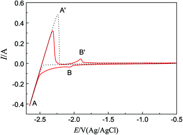 | ||
| Fig. 1 CVs obtained from LiCl–KCl eutectic on W electrode before and after the addition of TbCl3 (2 wt%); scan rate: 0.1 V s−1; temperature: 773 K; SW = 0.314 cm2. | ||
When TbCl3 was added in the eutectic, the CV (red line) exhibits a new pair of signals B/B′, observed at −2.05/−1.90 V, corresponding to the deposition and dissolution of Tb, respectively. The result is consistent with that obtained by ref. 36.
| Tb(III) + 3e− → Tb(0) | (1) |
Since the amount of electrodeposited Tb exceeds its solubility in liquid Bi, solid Tb–Bi intermetallic compounds will form, which results in liquid Bi electrode losing its homogeneity and the voltammetric response becoming less accurate, it is very important to avoid the formation of Tb–Bi intermetallics during the following electrochemical measurements on liquid Bi electrode.
Fig. 2 present the CVs obtained on liquid Bi electrode in LiCl–KCl eutectic and LiCl–KCl–TbCl3 melts, respectively. In the black curve, two new pairs of reduction/oxidation peaks are observed. In addition to peaks E′/E corresponding to the anodic dissolution of liquid Bi metal and reduction of dissolved Bi, the peaks C/C′, observed at −1.46/−1.17 V, should be correlated with the deposition and subsequent dissolution of Bi–Li alloy.
| Li(I) + e− → Liin liquid Bi | (2) |
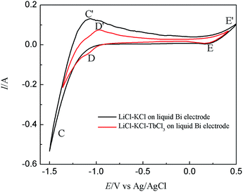 | ||
| Fig. 2 CVs obtained from LiCl–KCl eutectic on liquid Bi electrode before and after the addition of TbCl3 (2 wt%); scan rate: 0.1 V s−1; temperature: 773 K; SBi = 0.2 cm2. | ||
After the addition of TbCl3 (2 wt%) in the eutectic LiCl–KCl, the red curve shows that a new couple of cathodic/anodic wave D/D′, observed at −1.11/−1.03 V, locates at potential values more positive than the deposition/dissolution potential of Tb on W electrode, due to a lowering of the activity of the deposited Tb in the liquid Bi phase.
| Tb(III) + 3e− → Tbin liquid Bi | (3) |
From the shape of cathodic/anodic wave D/D′, it is that expected for a soluble–soluble exchange, which also suggest that Tb is not saturated in the liquid Bi phase when the potential below −1.25 V. A similar result was reported in ref. 23 and 24 in the case of La(III) and Ce(III) electroreduction on liquid Bi electrode.
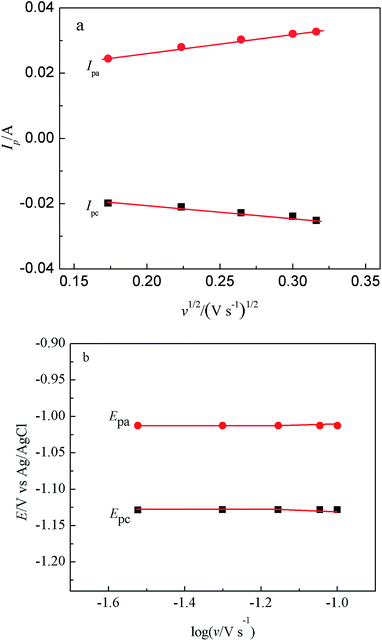
Fig. 3 presents a series of CVs gained in LiCl–KCl–TbCl3 melts on Bi pool electrode at various scan rates. The change of cathodic and anodic peak currents with the square root of the scan rate can be seen from Fig. 4(a). The linear relationship indicates the reduction process of Tb(III) on liquid Bi electrode is controlled by the diffusion of electroactive species. Furthermore, the reversibility of the system was examined by plotting the influence of the scan rates on the peak potentials. From Fig. 4(b), it can be seen that when the scan rate is lower than 0.07 V s−1, the peak potential, EP, is constant and independent of the scan potential rate. For higher scan rates, the values of the anodic and cathodic peak potentials shift slightly towards positive and negative ones. The experimental results illustrate that the reduction process of Tb(III) on liquid Bi electrode is quasi-reversible.
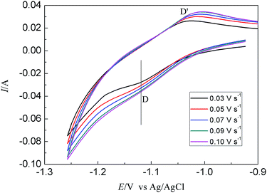 | ||
| Fig. 3 CVs obtained from LiCl–KCl–TbCl3 (2 wt%) melts on liquid Bi electrode at different scan rates at 773 K. | ||
Electrode reaction of Tb(III) on Bi film electrode in LiCl–KCl–BiCl3 melts
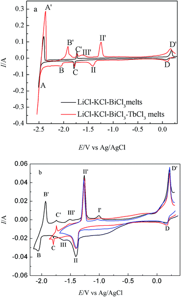
The peaks of C/C′ observed at −1.80/−1.73 V, between peaks of A/A′ and D/D′, should be ascribed to the formation of Li–Bi intermetallic compound which formed by under-potential deposition of Li on the pre-deposition Bi film electrode. The formation process of Li–Bi intermetallics can be expressed by the following three steps: (1): xBi(III) + 3xe− → xBi(0); (2): yLi(I) + ye− → yLi(0); (3): yLi + xBi → LiyBix. The overall process of the formation of Li–Bi alloy can be described as:
| yLi(I) + xBi(III) + (y + 3x)e− → LiyBix | (4) |
While TbCl3 (2 wt%) was added in LiCl–KCl–BiCl3 melts, the CV attained on Bi film electrode (red line in Fig. 5(a) is more complex and a series of new reduction/oxidation peaks are observed. In addition to the peaks A/A′, C/C′ and D/D′, peaks B/B′ should correspond to the reduction of Tb metal and its subsequent re-oxidation, respectively, based on the above results of LiCl–KCl–TbCl3 melts on W electrode (black line in Fig. 1). Between the peaks B/B′ and D/D′, a series of redox peaks correspond to the formation/dissolution of different Tb–Bi intermetallic compounds. In order to confirm the cathodic formation peaks with their corresponding anodic dissolution, the CVs were registered at different inversion cathodic potentials, and the results are presented in Fig. 5(b).
Three new anodic peaks, I′, II′ and III′ at −1.01 V, −1.26 V and −1.48 V, are ascribed to the dissolution of different Tb–Bi intermetallic compounds. Since metallic Tb deposited on Bi film electrode reacts with Bi film electrode to form Tb–Bi intermetallic compounds, the reduction potential of Tb(III)/Tb couple is observed at more positive potential values than that on W electrode, which indicates the formation of Tb–Bi intermetallic compounds on Bi film electrode.
| Tb(III) + xBi + 3e− → TbBix | (5) |
Based on the Tb–Bi binary phase diagram,37 there are three Tb–Bi intermetallic compounds, TbBi, TbBi3/4 and TbBi3/5 in the Tb–Bi system. Therefore, the three anodic peaks are related to the oxidation of TbBi, TbBi3/4 and TbBi3/5, respectively. We investigated the electrochemical behavior of La–Bi23 and Ho–Bi26 in previous work. A comparison of the cyclic voltammogram obtained on Bi film electrode in LiCl–KCl–RECl3 (RE = La, Ho) melts23,26 with in LiCl–KCl–TbCl3 melts show that (1) there is only one reduction/oxidation peak of Li on Bi film electrode; (2) reduction/oxidation peaks ascribed to all RE–Bi (RE = La, Tb, Ho) intermetallic compounds occur on Bi film electrode.
Compared with the CV of Tb(III) on Al electrode,31 there is a large differences. In the Tb–Al binary system, there are five intermetallic compounds. However, we can observe only one couple of reduction/oxidation peak on Al electrode. The difference may be that the diffusion of Tb on liquid Bi is faster than that on solid Al electrode.
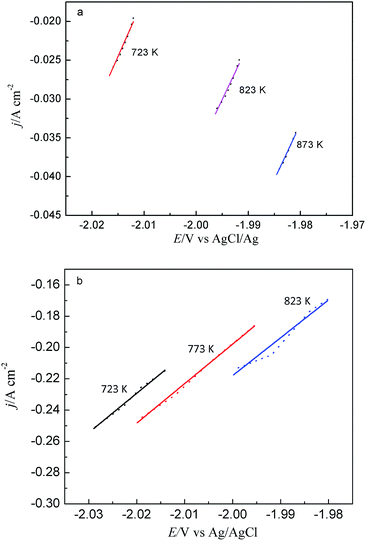
The exchange current density is an important reaction kinetics parameter, linked to the nucleation characteristics and morphology of electrodeposits. Thus, the linear polarization method, which utilizes the data from very low overpotentials, was employed in the present investigation. Butler–Volmer equation can be simplified at very low overpotentials to the expression as follows:
| j/η = j0(nF/RT) | (6) |
Fig. 6 shows the linear polarization plot of 2 wt% TbCl3 obtained on W and Bi film electrodes in LiCl–KCl molten salt at ±15 mV overpotentials and scan rate of 0.188 mV s−1. The slope of fitted line can be used to estimate the exchange current density j0. The calculated values for exchange current density j0 are listed in Table 1. It can be seen from Table 1 that the results obtained on W electrode are lower than those on Bi film electrode. The results indicates that the reduction rate of Tb(III) on W electrode is smaller than that on Bi film electrode.
| Temperature/K | j0/A cm−2 | |||
|---|---|---|---|---|
| 723 | 773 | 823 | 873 | |
| W electrode | 0.031 | — | 0.034 | 0.036 |
| Bi film electrode | 0.052 | 0.056 | 0.057 | — |
The measurements were conducted as following: firstly, the Bi film electrode was electrogenerated “in situ” by potentiostatic electrolysis at −0.4 V for a little period; then potentiostatic electrolysis was carried out to form a thin layer specimen of Tb on Bi film electrode at −2.5 V in the LiCl–KCl–BiCl3–TbCl3 melts. Since the reaction and interdiffusion occurs between deposited Tb metal and Bi film, different Tb–Bi phases can be formed. At the same time, the electrode potential would gradually shift to more positive values. During this process, a potential plateau can be observed when the composition of the electrode surface is within the range of two phase coexisting state.39,40 Then, the open circuit potential of the electrode was registered vs. time.
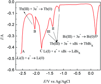
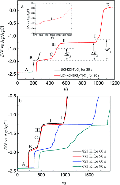
Fig. 9 presents the comparison of open circuit chronopotentiogram obtained in the KCl–LiCl–TbCl3 (2 wt%) melts on W electrode and Bi film electrode while applying a deposition potential of −2.50 V at 773 K. In the black line, the first potential plateau stays at around −2.41 V (plateau A), which is due to the presence of deposited Li metal and related to the Li(I)/Li(0) redox couple. After that, the second potential plateau B is ascribed to the redox couple of Tb(III)/Tb(0). The red line displays an open circuit chronopotentiogram obtained in LiCl–KCl–BiCl3 (0.2 wt%)-TbCl3 (2 wt%) melts on Bi film. In addition to the plateau A and B, the five new plateaus, C, III, II, I and D, are observed at −1.748 V, −1.496 V, −1.263 V, −1.129 V and 0.129 V, respectively. The potential plateau C corresponds to the two phases coexisting of Li–Bi intermetallic compound and plateau D is ascribed to Bi(III)/Bi(0) system. Since there are three thermodynamic stable Tb–Bi intermetallic compounds, TbBi, TbBi3/4 and TbBi3/5 in the Tb–Bi system,33 the three plateaus, I, II and III, are associated with the two phases coexisting of three different Tb–Bi intermetallic compounds, respectively. Thus, the plateaus shown in Fig. 9(a) could be considered to correspond to the following equilibriums:
| Plateau A: Li(I) + e− ↔ Li | (7) |
| Plateau B: Tb(III) + 3e− ↔ Tb | (8) |
| Plateau C: Li(I) + e− + xBi ↔ LiBix | (9) |
| Plateau D: Bi(III) + 3e− ↔ Bi | (10) |
| Plateau I: Tb(III) + 3e− + Bi ↔ TbBi | (11) |
| Plateau II: Tb(III) + 3e− + 3TbBi ↔ 4TbBi3/4 | (12) |
| Plateau III: Tb(III) + 3e− + 4TbBi3/4 ↔ 5TbBi3/5 | (13) |
Fig. 9(b) presents the open circuit chronopotentiograms obtained at different temperatures. In order to ensure the reproducibility of the experiment, the same measurement was repeated several times.
The equilibrium potentials measured by reference to the Ag/AgCl couple were converted to the electromotive forces (emf) against Tb(0), which make it possible to estimate the standard molar Gibbs energies of formation for Tb–Bi intermetallics.11,12,18,38,41,42
The emf related to the chemical composition of Tb–Bi alloys is correlated with the activity of Tb, by the following expression:
ΔḠTb = −3FΔE = RT![[thin space (1/6-em)]](https://www.rsc.org/images/entities/char_2009.gif) ln ln![[thin space (1/6-em)]](https://www.rsc.org/images/entities/char_2009.gif) aTb aTb
| (14) |
These thermodynamic properties are calculated and listed in Table 2. The activities of Tb in Tb–Bi intermetallic compounds are found to be in the order of 10−19 to 10−9.
| T/K | Eeq/V vs. Ag/AgCl | ΔE/V vs. Tb(III)/Tb | ΔG⊖f/kJ mol−1 | aTb |
|---|---|---|---|---|
| Plateau B (Tb) | ||||
| 673 | −1.988 | |||
| 723 | −1.974 | |||
| 773 | −1.960 | |||
| 823 | −1.946 | |||
![[thin space (1/6-em)]](https://www.rsc.org/images/entities/char_2009.gif) |
||||
| Plateau I two phases coexisting state between TbBi and Bi | ||||
| 673 | −1.146 | 0.842 | −244 | 1.20 × 10⁻¹⁹ |
| 723 | −1.138 | 0.836 | −242 | 3.27 × 10⁻¹⁸ |
| 773 | −1.129 | 0.831 | −241 | 5.53 × 10⁻¹⁷ |
| 823 | −1.125 | 0.821 | −238 | 8.21 × 10⁻¹⁶ |
![[thin space (1/6-em)]](https://www.rsc.org/images/entities/char_2009.gif) |
||||
| Plateau II two phases coexisting state between TbBi and Tb4Bi3 | ||||
| 673 | −1.274 | 0.714 | −207 | 9.04 × 10⁻¹⁷ |
| 723 | −1.267 | 0.707 | −205 | 1.63 × 10⁻¹⁵ |
| 773 | −1.263 | 0.697 | −202 | 2.31 × 10⁻¹⁴ |
| 823 | −1.254 | 0.682 | −200 | 1.93 × 10⁻¹³ |
![[thin space (1/6-em)]](https://www.rsc.org/images/entities/char_2009.gif) |
||||
| Plateau III two phases coexisting state between Tb4Bi3 and Tb5Bi3 | ||||
| 673 | −1.516 | 0.472 | −137 | 2.49 × 10⁻¹¹ |
| 723 | −1.507 | 0.467 | −135 | 1.71 × 10⁻¹⁰ |
| 773 | −1.496 | 0.464 | −134 | 8.37 × 10⁻¹⁰ |
| 823 | −1.487 | 0.459 | −133 | 3.68 × 10⁻⁹ |
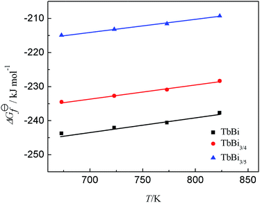
The standard molar Gibbs free energies of formation ΔG⊖f for Tb–Bi intermetallic compound are estimated by the equation listed in Table 3. The calculated results at different temperature are also presented in Table 3. The change of the Gibbs free energy of formation for each Tb–Bi intermetallic compound with the temperature was plotted in Fig. 10, from which it is possible to estimate the molar entropy and enthalpy of formation and the constant of formation reaction for each Tb–Bi intermetallic compound. These thermodynamic properties of Tb–Bi intermetallic compounds are listed in Table 4.
| Intermetallic compound | Formula | T/K | ΔG⊖f/kJ mol−1![[thin space (1/6-em)]](https://www.rsc.org/images/entities/char_2009.gif) |
|---|---|---|---|
| TbBi | ΔG⊖f(TbBi) = −3FΔE1 | 673 | −244 |
| 723 | −242 | ||
| 773 | −241 | ||
| 823 | −238 | ||
| TbBi3/4 | ΔG⊖f(TbBi3/4) = 1/4[3ΔG⊖f(TbBi) − 3FΔE2] | 673 | −235 |
| 723 | −233 | ||
| 773 | −231 | ||
| 823 | −228 | ||
| TbBi3/5 | ΔG⊖f(TbBi3/5) = 1/5[4ΔG⊖f(TbBi3/4) − 3FΔE3] | 673 | −215 |
| 723 | −213 | ||
| 773 | −212 | ||
| 823 | −209 |
| Intermetallic compounds | Formation reaction | ΔH⊖f/kJ mol−1 | ΔS⊖f/J mol−1 K−1 | K⊖ |
|---|---|---|---|---|
| TbBi | Tb + Bi = TbBi | −270 | −38.8 | exp(−32.4/T + 4.66) |
| TbBi3/4 | Tb + 3/4Bi = TbBi3/4 | −262 | −40.1 | exp(−31.5/T + 4.83) |
| TbBi3/5 | Tb + 3/5Bi = TbBi3/5 | −240 | −37.0 | exp(−28.8/T + 4.45) |
Galvanostatic and potentiostatic electrolysis and characterization of the deposits
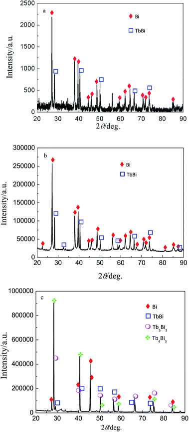
On the basis of the results from cyclic voltammetry, square wave voltammetry, chronopotentiometry and open circuit chronopotentiometry, galvanostatic and potentiostatic electrolysis were employed on Bi film electrode in LiCl–KCl–BiCl3–TbCl3 (4.9 wt%) melts. However, we could not collect the Tb–Bi alloy, because the Tb–Bi alloy prepared is always dispersed in the molten salts, no matter what the temperature was. Thus, the Tb–Bi alloys was formed on liquid Bi electrode in LiCl–KCl–TbCl3 (4.9 wt%) melts by galvanostatic and potentiostatic electrolysis. Fig. 11 shows the XRD patterns of Tb–Bi alloys gained by galvanostatic and potentiostatic electrolysis. The results of XRD shown in Fig. 11(a) and (b) indicate that only one Tb–Bi intermetallic compound TbBi was produced by galvanostatic electrolysis at −0.02 A and −0.05 A for 3.5 h. However, it can be seen from Fig. 11(c), the Tb–Bi intermetallic compounds, TbBi, Tb4Bi3 and Tb5Bi3, were prepared by potentiostatic electrolysis at −1.45 V for 6 h on liquid Bi electrode in LiCl–KCl–TbCl3 (4.9 wt%) melts. Fig. 12 presents the SEM images of Tb–Bi alloys obtained by galvanostatic electrolysis at −0.02 A and −0.05 A for 3.5 h, respectively. Making a comparison of Fig. 12(a) and (b), we can observe the Tb–Bi alloys with different surface morphologies.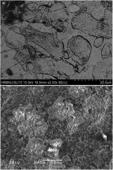 | ||
| Fig. 12 SEM images obtained in LiCl–KCl–TbCl3 (4.9 wt%) melts on liquid Bi electrode by galvanostatic electrolysis for 3.5 h. (a) −0.02 A; (b) −0.05 A. | ||
Conclusions
The electrochemical reaction of Tb(III) was studied on different electrodes (W electrode, liquid Bi electrode and Bi film electrode) in LiCl–KCl–TbCl3 melts by a series of electrochemical techniques. The exchange current densities of Tb were estimated on W substrate at different temperatures by the linear polarization method. The result of cyclic voltammetry on liquid Bi electrode suggested that the electrochemical reaction of Tb(III) to Tbin liquid Bi was a quasi-reversible and diffusion-controlled process. Cyclic voltammogram, square wave voltammogram and chronopotentiogram exhibit three new reduction signals of Tb(III) on Bi film electrode than that on W electrode in LiCl–KCl–TbCl3 melts due to the formation of Tb–Bi intermetallic compounds.The thermodynamic properties of Tb–Bi intermetallic compounds in the temperature range from 673 K to 823 K were calculated by emf measurements. From the linear dependence of the standard molar Gibbs energies of formation of Tb–Bi intermetallic compounds with temperature, we obtained the molar entropies and enthalpies of formation as well as equilibrium constant of formation reaction for each Tb–Bi intermetallic compound. Electrochemical formation of Tb–Bi alloys was performed in LiCl–KCl–TbCl3 melts on liquid Bi electrode by galvanostatic and potentiostatic electrolysis, respectively. The results of XRD of the deposits showed the formation of TbBi, TbBi3/4 and TbBi3/5 intermetallic compounds.
Acknowledgements
The work was financially supported by the National Natural Science foundation of China (11575047, 11675044, 21173060, and 21271054), the Major Research plan of the National Natural Science Foundation of China (91326113 and 91226201), Natural Science Foundation of Heilongjiang Province of China (No. QC2013C011) and the Fundamental Research funds for the Central Universities (HEUCF2016012).References
- Y. U. Chang, Nucl. Technol., 1989, 88, 129–138 CrossRef CAS.
- T. Inoue, M. Sakata, H. Miyashiro, A. Sasahara and T. Matsumura, Nucl. Technol., 1991, 93, 206–220 CAS.
- T. Koyama, T. Kinoshita, T. Inoue, M. Ougier, R. Malmbeck, J. P. Glatz and L. Koch, J. Nucl. Sci. Technol., 2002, 3, 765–768 CrossRef.
- S. H. Kim, S. Paek, T. J. Kim, D. Y. Park and D. H. Ahn, Electrochim. Acta, 2012, 85, 332–335 CrossRef CAS.
- K. Uozomi, M. Iizuka, T. Kato, T. Inoue, O. Shirai, T. Iwai and Y. Arai, J. Nucl. Mater., 2004, 325, 34–43 CrossRef.
- Y. Sakamura, O. Shirai, T. Iwai and Y. Suzuki, J. Alloys Compd., 2001, 321, 76–83 CrossRef CAS.
- G. Y. Kim, D. Yoon, S. Paek, S. H. Kim, T. J. Kim and D. H. Ahn, J. Electroanal. Chem., 2012, 682, 128–135 CrossRef CAS.
- T. Murakami and T. Koyama, J. Electrochem. Soc., 2011, 158, F147–F153 CrossRef CAS.
- D. Yoon, S. Phongikaroon and J. Zhang, J. Electrochem. Soc., 2016, 163, E97–E103 CrossRef CAS.
- H. Hayashi, M. Akabori and K. Minato, Nucl. Technol., 2008, 162, 129–134 CAS.
- H. Shibata, H. Hayashi, M. Akabori, Y. Arai and M. Kurata, J. Phys. Chem. Solids, 2014, 75, 972–976 CrossRef CAS.
- O. Shirai, A. Uehara, T. Fujii and H. Yamana, J. Nucl. Mater., 2005, 344, 142–145 CrossRef CAS.
- O. Shirai, M. Iizuka, T. Iwai, Y. Suzuki and Y. Arai, J. Electroanal. Chem., 2000, 490, 31–36 CrossRef CAS.
- O. Shirai, K. Uozumi, T. Iwai and Y. Arai, J. Appl. Electrochem., 2004, 34, 323–330 CrossRef CAS.
- S. Vandarkuzhali, M. Chandra, S. Ghosh, N. Samanta, S. Nedumaran, B. P. Reddy and K. Nagarajan, Electrochim. Acta, 2014, 145, 86–98 CrossRef CAS.
- T. Kato, T. Inoue, T. Iwai and Y. Arai, J. Nucl. Mater., 2006, 357, 105–114 CrossRef CAS.
- Y. Castrillejo, P. Hernández, R. Fernández and E. Barrado, Electrochim. Acta, 2014, 147, 743–751 CrossRef CAS.
- Y. Castrillejo, R. Bermejo, A. M. Martínez, E. Barrado and P. D. Arocas, J. Nucl. Mater., 2007, 360, 32–42 CrossRef CAS.
- Y. Castrillejo, M. R. Bermejo, P. D. Arocas, A. M. Martínez and E. Barrado, J. Electroanal. Chem., 2005, 579, 343–358 CrossRef CAS.
- Y. Castrillejo, F. Oduber and E. Barrado, RSC Adv., 2016, 6, 71719–71726 RSC.
- J. Serp, P. Lefebvre, R. Malmbeck, J. Rebizant, P. Vallet and J. P. Glatz, J. Nucl. Mater., 2005, 340, 266–270 CrossRef CAS.
- M. Kurata, Y. Sakamura and T. Matsui, J. Alloys Compd., 1996, 234, 83–92 CrossRef CAS.
- M. Li, Q. Q. Gu, W. Han, X. M. Zhang, Y. Sun, M. L. Zhang and Y. D. Yan, RSC Adv., 2015, 5, 82471–82480 RSC.
- Y. Castrillejo, M. R. Bermejo, P. D. Arocas, F. de la Rosa and E. Barrado, Electrochemistry, 2005, 73, 636–643 CAS.
- T. Jiang, S. M. Peng, M. Li, T. T. Pei, W. Han, Y. Sun and M. L. Zhang, Acta Phys.-Chim. Sin., 2016, 32, 1708–1714 CAS.
- W. Han, Z. Y. Li, M. Li, W. L. Li, X. M. Zhang, X. G. Yang, M. L. Zhang and Y. Sun, J. Electrochem. Soc., 2017, 164, E62–E70 CrossRef CAS.
- J. Serp, P. Lefebvre, R. Malmbeck, J. Rebizant, P. Vallet and J. P. Glatz, J. Nucl. Mater., 2005, 340, 266–270 CrossRef CAS.
- O. Shirai, M. Iizuka, T. Iwai and Y. Arai, Anal. Sci., 2001, 17, 51–57 CrossRef CAS PubMed.
- K. Liu, L. Y. Yuan, Y. L. Liu, X. L. Zhao, H. He, G. A. Ye, Z. F. Chai and W. Q. Shi, Electrochim. Acta, 2014, 130, 650–659 CrossRef CAS.
- P. Chamelot, L. Massot, L. Cassayre and P. Taxil, Electrochim. Acta, 2010, 55, 4758–4764 CrossRef CAS.
- M. Li, Q. Q. Gu, W. Han, Y. D. Yan, M. L. Zhang, Y. Sun and W. Q. Shi, Electrochim. Acta, 2015, 167, 139–146 CrossRef CAS.
- H. Konishi, K. Mizuma, H. Ono, E. Takeuchi, T. Nohira and T. Oishi, ECS Trans., 2012, 50, 561–569 CrossRef.
- S. Rayaprolu and D. Chidambaram, ECS Trans., 2014, 58, 51–66 CrossRef.
- W. Han, Q. N. Sheng, M. L. Zhang, M. Li, T. T. Sun, Y. C. Liu, K. Ye, Y. D. Yan and Y. C. Wang, Metall. Mater. Trans. B, 2014, 45, 929–935 CrossRef CAS.
- F. Seon, G. Picard and B. Tremillon, Electrochim. Acta, 1983, 28, 209–215 CrossRef CAS.
- M. R. Bermejo, J. Gómez, A. M. Martínez, E. Barrado and Y. Castrillejo, Electrochim. Acta, 2008, 53, 5106–5112 CrossRef CAS.
- S. L. Wang, Z. B. Hu, F. Gao, C. P. Wang and X. J. Liu, J. Phase Equilib. Diffus., 2011, 32, 441–446 CrossRef CAS.
- H. Konishi, T. Nishikiori, T. Nohira and Y. Ito, Electrochim. Acta, 2003, 48, 1403–1408 CrossRef CAS.
- Y. Castrillejo, M. R. Bermejo, A. I. Barrado, R. Pardo, E. Barrado and A. M. Martinez, Electrochim. Acta, 2005, 50, 2047–2057 CrossRef CAS.
- Y. Castrillejo, M. R. Bermejo, P. D. Arocas, A. M. Martinez and E. Barrado, J. Electroanal. Chem., 2005, 575, 61–74 CrossRef CAS.
- P. Taxil and J. Mahenc, J. Appl. Electrochem., 1987, 17, 261–269 CrossRef CAS.
- Y. Castrillejo, A. Vega, M. Vega, P. Hernández, J. A. Rodriguez and E. Barrado, Electrochim. Acta, 2014, 118, 58–66 CrossRef CAS.
| This journal is © The Royal Society of Chemistry 2017 |

