 Open Access Article
Adsorption of fluoride at the interface of water with calcined magnesium–ferri–lanthanum hydrotalcite-like compound
Peng Wua,
Jishan Wua,
Ling Xiac,
Yao Liud,
Linya Xua and
Shaoxian Song *ab
*ab
aSchool of Resources and Environmental Engineering, Wuhan University of Technology, Luoshi Road 122, Wuhan, Hubei 430070, China. E-mail: ssx851215@whut.edu.cn
bHubei Key Laboratory of Mineral Resources Processing and Environment, Luoshi Road 122, Wuhan, Hubei 430070, China
cHubei Provincial Collaborative Innovation Center for High Efficient Utilization of Vanadium Resources, Luoshi Road 122, Wuhan, Hubei 430070, China
dDepartment of Pharmacy, The First People's Hospital of Xiushui County, Jiujiang, Jiangxi 332400, China
First published on 16th May 2017
Abstract
In this work, a new adsorbent, Mg/Fe/La hydrotalcite-like compound (defined as Mg/Fe/La HLc), was synthesized with a facile one-step hydrothermal method for removing fluoride from water. Several measurements, such as XRD, FT-IR, SEM, XPS and N2 adsorption–desorption technique, were used to characterize the adsorbent and to approach into the adsorption of fluoride at the interface of water with calcined Mg/Fe/La hydrotalcite-like compound (defined as Mg/Fe/La CHLc). The experimental results have shown that the adsorption was well described by the pseudo-second-order model and followed Langmuir isotherm. The maximum adsorption capacity reached 60 mg g−1, and the desorption could be easily realized in a aqueous Na2CO3 solution, indicating that the Mg/Fe/La CHLc could be used as a potential adsorbent for effectively removing fluoride from water. The mechanisms of the adsorption might be attributed to the chemisorption due to the complexation of fluoride in water with lanthanum on the surfaces of the Mg/Fe/La CHLc, besides of the surface adsorption and interlayer adsorption due to the “memory effect” of hydrotalcite. In addition, it was found that the element of lanthanum in the adsorbent played a great role in the adsorption of fluoride in water.
1. Introduction
Fluoride water contamination derived from mineral weathering or chemical industry has become a worldwide concern due to its severe threat to living organisms, in particular humans.1 Long-term ingestion of high-concentration fluorides in drinking water can lead to health problems such as dental fluorosis, skeletal fluorosis and deformation of bones even lesions of the organs.1,2 Unfortunately, over 200 million people in the world are influenced by the fluoride concentrations in drinking water higher than 1.5 mg L−1, a guideline line set by WHO.3 Therefore, it is significant to pay attentions on fluoride removal from drinking water.The methods for removing fluoride from water include precipitation,4 adsorption,5 electrodialysis,6 reverse osmosis,7 electrsorption8 and membrane filtration.9 Among them, adsorption has been considered to be the superior technique for defluoridation because of its low cost, easy operation, minimized waste disposal, environment-friendliness and applicability to decentralized water supply system.10 Numerous natural or synthetic materials have been used as fluoride adsorbents, such as red mud, alum sludge, carbon nanotubes and mixed metal oxides.11–15 However, the adsorption and desorption performance was limited because of the structure of these material. It might be a good idea to use nano-scale layered materials to remove fluoride from aqueous solutions.
Layered double hydroxides (LDH), also known as hierarchical anionic clays, have attracted considerable attentions due to their case applicability such as catalysts, nanotechnology and environmental decontamination. The general formula of LDH can be represented as  , where M2+ and M3+ represent divalent metal cations (Mg2+, Ni2+, Cu2+, Zn2+, etc.) and trivalent metal cations (Fe3+, Al3+, Cr3+, La3+, etc.), respectively, x is the molar ratio of M3+/(M2+ + M3+), An− is the intercalated anion (CO32−, NO3−, Cl−, etc.). The positive surplus charges of the metal hydroxide layer are balanced by interlayer anions. With thermal decomposition, LDH could turn into mixed metal oxides due to the elimination of interlayer anions. The oxides could be reconstructed into their original layered structure by adsorbing various anions in aqueous solution during the rehydration process, which is termed “memory effect”.16 Because of the high anion-exchange capacities and large surface area, the calcined LDH have been considered as effective adsorbent for removing fluoride in water.17,18
For these layered compounds, most studies focus on the aluminum-based ones such as Mg/Al LDH.19,20 However, the high residual concentration of aluminum after adsorption in drinking water has been proven to be a potential risk factor for human health.21 Recently, a large amount of researches have been done to develop iron-based adsorbents for removing hazardous anions from water.22–24 In addition, rare earth metals (La, Ce, ect.) have been added into the oxides for fluoride removal, showing a strong affinity to fluoride ion due to their high electropositivity.25–27 Accordingly, introducing La into the Mg/Fe layered compound to develop an Mg/Fe/La hydrotalcite-like compound with hierarchically porous structure might be a good adsorbent for fluoride removal from water.
In this work, a new material, Mg/Fe/La hydrotalcite-like compound, was synthesized with a facile one-step hydrothermal method, and then the Mg/Fe/La CHLc was tested on the adsorption of fluoride in aqueous solutions. The objectives of this study are to develop a new and effective adsorbent for fluoride removal from water and to approach into the mechanisms of the adsorption and desorption fluoride at the interface of Mg/Fe/La HLC/water.
2. Materials and methods
2.1 Reagents and chemicals
All the reagents used in the study were all of analytical grade and purchased from Sinopharm Chemical Regent Co., Ltd. (China). Ultrapure water was used throughout the synthesis and adsorption experiments.2.2 Preparation of adsorbent
The Mg–Fe–La hydrotalcite-like compounds for a constant Mg2+![[thin space (1/6-em)]](https://www.rsc.org/images/entities/char_2009.gif) :
:![[thin space (1/6-em)]](https://www.rsc.org/images/entities/char_2009.gif) (Fe3+ + La3+) ratio of 3
(Fe3+ + La3+) ratio of 3![[thin space (1/6-em)]](https://www.rsc.org/images/entities/char_2009.gif) :
:![[thin space (1/6-em)]](https://www.rsc.org/images/entities/char_2009.gif) 1 with different La3+
1 with different La3+![[thin space (1/6-em)]](https://www.rsc.org/images/entities/char_2009.gif) :
:![[thin space (1/6-em)]](https://www.rsc.org/images/entities/char_2009.gif) (Fe3+ + La3+) ratios were synthesized using hydrothermal method. In detail, the solution containing Fe(NO3)3·9H2O, Mg(NO3)2·6H2O and La(NO3)3·6H2O with desired amount was mixed with 50 mL water, and then transferred into a 100 mL Teflon-lined autoclave after taking ultrasonic oscillation for 10 minutes and heated at 150 °C for 12 h in a muffle furnace. After the furnace chamber cooled down, the precipitate was separated by the suction filter machine and washed with de-ionized water until the pH value was close to 7. The wet solid was slowly dried in the oven at 70 °C for 10 h, and finally calcined at different temperatures (150, 300, 400, 500, 600, 700, 800 °C) for 3 h to obtain Mg/Fe/La CHLc. The calcined and uncalcined ones were subsequently used for adsorption experiments.
(Fe3+ + La3+) ratios were synthesized using hydrothermal method. In detail, the solution containing Fe(NO3)3·9H2O, Mg(NO3)2·6H2O and La(NO3)3·6H2O with desired amount was mixed with 50 mL water, and then transferred into a 100 mL Teflon-lined autoclave after taking ultrasonic oscillation for 10 minutes and heated at 150 °C for 12 h in a muffle furnace. After the furnace chamber cooled down, the precipitate was separated by the suction filter machine and washed with de-ionized water until the pH value was close to 7. The wet solid was slowly dried in the oven at 70 °C for 10 h, and finally calcined at different temperatures (150, 300, 400, 500, 600, 700, 800 °C) for 3 h to obtain Mg/Fe/La CHLc. The calcined and uncalcined ones were subsequently used for adsorption experiments.
2.3 Characterization methods
The as-prepared Mg/Fe/La HLc and Mg/Fe/La CHLc before and after fluoride adsorption were characterized by scanning electron microscopic (SEM), specific surface and pore size analysis, X-ray diffraction (XRD), Fourier transform infrared spectroscopy (FT-IR) and X-ray photoelectron spectroscopy (XPS). The surface morphology of the materials were determined by SEM operating at 20 kV (JSM-IT300, JEOL, Japan). The phase components and crystallinity of the Mg/Fe/La materials were determined by X-ray Diffraction analysis (D8, Brucker, Germany). The specific surface area and pore structure of the samples (degassed at 150 °C in vacuum) were conducted by nitrogen adsorption–desorption at 77 K (V-Sorb2800P, Gold APP, China). FT-IR spectroscopy (2000, Thermo Nicolet, America) was used to detect the chemical bonds presented on the samples. Additionally, the functional groups and the chemical state of the element before and after adsorption were determined by X-ray photoelectron spectroscopy (XPS) (2000, Thermo Electron VG Multilab, America).2.4 Batch adsorption experiments
The fluoride adsorption experiments were estimated in batch mode in terms of molar ratio of nitrate, contact time, fluoride concentration and initial pH. The adsorption experiments except isotherm experiments were performed in triplicate with 100 mL initial fluoride concentration of 5 mg L−1 in 150 mL capacity PVC conical flask and added a defined amount of Mg/Fe/La CHLc in a mechanical shaker at the speed of 150 rpm at 35 ± 1 °C. The adsorption isotherm experiments were obtained by adding 0.05 g Mg/Fe/La CHLc to 100 mL fluoride solutions with a concentration range of 5–130 mg L−1 at pH 6.8 ± 0.1 under 35 ± 1 °C for 10 h in a mechanical shaker at the speed of 150 rpm min−1. The effect of pH on the adsorption was conducted within a pH range of 6 to 11 and the pH value of the solution was adjusted by 0.1 mol L−1 NaOH or 0.1 mol L−1 HCl solutions. The concentration of fluoride ion was measured according to the Chinese National Standard HJ 488-2009 “Water Quality-Determination of Fluoride and Fluoride Reagent Spectrophotometric Method”, in which fluoride was determined with a spectrophotometer (Orion Aquamate 8000, Thermo Fisher Scientific, America) based on the fluoride/lanthanum(III)/alizarin mixed-ligand blue ternary complex at a wavelength of 620 nm.28 And the fluoride adsorption capacity was calculated by using the following equation:
 | (1) |
 | (2) |
2.5 Desorption and regeneration
The adsorption–desorption studies were conducted as follows: 0.5 g Mg/Fe/La CHLc was mixed with 1000 mL 5 ppm of fluoride solution for 8 h for full adsorption. After adsorption the adsorbent was separated by filtration with 0.45 μm microfiltration membrane and washed several times with deionized water. The desorption studies were carried out by adding the fluoride loaded Mg/Fe/La CHLc into 0.1 mol L−1 Na2CO3 solution and the mixture was shaken for 8 h. After desorption, the adsorbent was separated by filtration as above-mentioned and dried, followed by calcination in the muffle furnace for 3 h for further adsorption experiments. The adsorption–desorption process was repeated for 5 times and the F concentration in the process was measured and recorded.3. Results and discussion
3.1 Characterization of materials
The XRD patterns of the synthesized Mg/Fe/La HLc and its calcination product were shown in Fig. 1. The characteristic peaks of the Mg/Fe/La HLc (Fig. 1a) (003), (006), (009), (015), (018), (110), (115), corresponding to the diffraction peaks of Mg6Fe2 (OH)16 CO3·4H2O (JCPDS cards: 24-1091), can be assigned to typical peaks of layered double hydroxide.29 Meanwhile, the diffraction peaks with symmetrical planes and sharp peaks demonstrated the high crystallization of Mg/Fe/La HLc. This was suggesting that synthesized material was hydrotalcite-like compound. However, the characteristic peaks of Mg/Fe/La CHLc disappeared in corresponding positions after calcination at 600 °C (Fig. 1b), this was attributed to that the calcined Mg/Fe/La HLc formed the amorphous mixed oxides. Moreover, after adsorption of F, as shown in Fig. 1c, the 2θ value of the characteristic peaks of Mg/Fe/La CHLc-F and Mg/Fe/La HLc were utterly same, it was indicated that Mg/Fe/La CHLc possessed “memory effect”.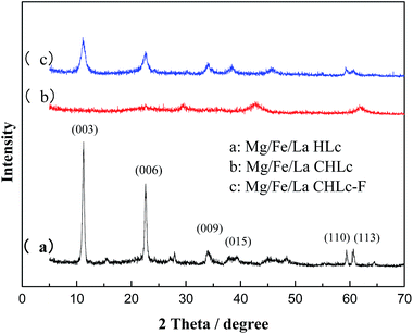 | ||
| Fig. 1 XRD patterns of the Mg/Fe/La HLc (a), Mg/Fe/La CHLc calcined at 600 °C before (b) and after adsorption of F (c). | ||
The specific surface areas, pore volume and average pore diameter of the materials were calculated via the N2 adsorption–desorption technique. As shown in the Table 1, the specific surface area, average pore diameter and pore volume of Mg/Fe/La HLc were 18.7 m2 g−1, 26.99 nm and 0.131 cm3 g−1, while the Mg/Fe/La CHLc were 59.3 m2 g−1, 22.31 nm and 0.347 cm3 g−1, respectively. The surface area and pore volume considerably increased but the average pore diameter decreased after calcination. It revealed that CO32− in the interlayer was transformed to CO2 and the layers were destroyed during the calcination process, leading to a porous structure in the Mg/Fe/La CHLc. These properties provide favorable condition for fluoride removal.
| Materials | SBET, m2 g−1 | Smic, m2 g−1 | Smes, m2 g−1 | VT, cm3 g−1 | Vmic, cm3 g−1 | Vmes, cm3 g−1 | D, nm |
|---|---|---|---|---|---|---|---|
| Mg/Fe/La HLc | 18.7 | 0 | 18.7 | 0.131 | 0.006 | 0.126 | 26.99 |
| Mg/Fe/La CHLc | 59.3 | 0 | 59.3 | 0.347 | 0.021 | 0.331 | 22.31 |
| Mg/Fe/La CHLc-F | 27.9 | 0 | 27.9 | 0.249 | 0.0126 | 0.239 | 16.99 |
The FT-IR spectra of Mg/Fe/La HLc before and after calcination were shown in Fig. 2. The broad and intense absorption band at around 3416 cm−1 was attributed to the bending vibration of the water molecule and OH stretching frequency in interlayer region of Mg/Fe/La HLc.30 The peaks at 2924 cm−1, 2534 cm−1, 1437 cm−1, 884 cm−1 and 748 cm−1 were assigned to the asymmetric stretching bands of the carbonate or bitrate radical.31,32 It is important to mention that the intensity of the OH and CO32− band were diminished or lost after calcination at 600 °C, revealing that water molecules and CO32− were continuously removed and released from the interlayer of the oxides during the calcination. The samples showing bands in the range of 800 cm−1 to 474 cm−1 were attributed to metal–oxygen (M–O) and metal–hydroxyl (M–OH) band vibrations.33
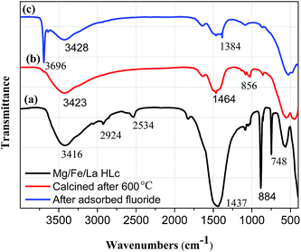 | ||
| Fig. 2 FT-IR spectra of (a) Mg/Fe/La HLc, Mg/Fe/La HLc calcined at 600 °C before (b) and after (c) adsorbed fluoride. | ||
SEM analyses were performed on the samples to investigate the surface morphology and the results were shown in Fig. 3. It can be seen from the Fig. 3a, the morphology of Mg/Fe/La HLc was dominated by homogeneous, plate-like structures with visible edges and smooth surface. After calcinated at 600 °C, a rough surface can be obviously observed in Fig. 1b, and the material presented an irregular structure. This was due to the decomposition of hydroxides into mixed oxides and a porous structure was formed during the calcination process.
 | ||
| Fig. 3 SEM images of Mg/Fe/La HLc (a), Mg/Fe/La HLc calcined at 600 °C before (b) and after (c) adsorbed fluoride. | ||
3.2 Adsorption performance
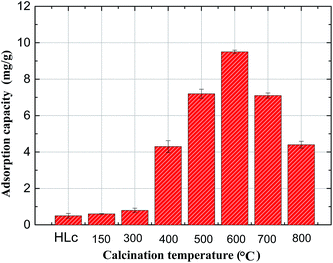
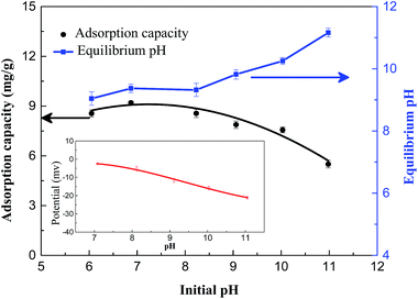
![[thin space (1/6-em)]](https://www.rsc.org/images/entities/char_2009.gif) :
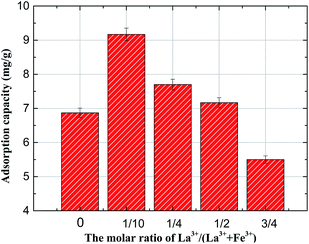
:![[thin space (1/6-em)]](https://www.rsc.org/images/entities/char_2009.gif) 1. As shown in Fig. 5, the La3+/(Fe3+ + La3+) molar ratio had a significant effect on the fluoride adsorption capacity. It was obviously observed that with the increasing percentage of La3+ addition, the F removal efficiency first climb up and then decline. The highest capacity (9.17 mg g−1) was found at a La3+/(Fe3+ + La3+) molar ratio of 1/10, which was much higher than that without La addition (6.87 mg g−1), indicating that adding lanthanum to the Mg/Fe/La HLc could contribute to improve the adsorption capacity of Mg/Fe CHLc for fluoride uptake. Reasons for this enhancement can be ascribed to the stronger affinity between La and fluoride ion than Fe.15 However, the decreased uptake capacity with the further increasing percentage of La may be due to that the larger ion radius of lanthanum (0.1032 nm) than iron (0.055 nm), lead to impede the easy intercalation of La3+ in the hydrotalcites galleries.36 Considering the removal efficiency and economic cost, the molar ratio for La3+/(Fe3+ + La3+) of 1/10 (corresponding to a La3+ percentage of 2.5%) was selected for the further studies.
1. As shown in Fig. 5, the La3+/(Fe3+ + La3+) molar ratio had a significant effect on the fluoride adsorption capacity. It was obviously observed that with the increasing percentage of La3+ addition, the F removal efficiency first climb up and then decline. The highest capacity (9.17 mg g−1) was found at a La3+/(Fe3+ + La3+) molar ratio of 1/10, which was much higher than that without La addition (6.87 mg g−1), indicating that adding lanthanum to the Mg/Fe/La HLc could contribute to improve the adsorption capacity of Mg/Fe CHLc for fluoride uptake. Reasons for this enhancement can be ascribed to the stronger affinity between La and fluoride ion than Fe.15 However, the decreased uptake capacity with the further increasing percentage of La may be due to that the larger ion radius of lanthanum (0.1032 nm) than iron (0.055 nm), lead to impede the easy intercalation of La3+ in the hydrotalcites galleries.36 Considering the removal efficiency and economic cost, the molar ratio for La3+/(Fe3+ + La3+) of 1/10 (corresponding to a La3+ percentage of 2.5%) was selected for the further studies.
ln(qe−qt) = ln![[thin space (1/6-em)]](https://www.rsc.org/images/entities/char_2009.gif) qe − k1t qe − k1t
| (3) |
 | (4) |
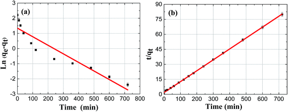
The kinetics results by linearized version of F adsorption on Mg/Fe/La CHLc were described in Fig. 7(a) and (b), and the associated kinetic parameters were summarized in Table 2. The adsorption was fitting better with the pseudo second-order kinetics equation according to the R2 and the theoretical adsorption capacity (qe,cal) values calculated from the pseudo-second-order model (9.17 mg g−1) were in agreement with the experimental adsorption capacity (qe,exp) values (9.1 mg g−1), both suggesting that the adsorption kinetic of fluoride on Mg/Fe/La CHLc in water follows the pseudo-second-order model and implying that the adsorption process was chemisorption.
| Materials | qe,exp (mg g−1) | Pseudo-first-order kinetics | Pseudo-second-order kinetics | ||||
|---|---|---|---|---|---|---|---|
| qe,cal (mg g−1) | K1 (min−1) | R2 | qe,cal (mg g−1) | K2 (g mg−1 min−1) | R2 | ||
| Ma/Fe/La CHLc | 9.1 | 8.55 | 0.0342 | 0.8759 | 9.17 | 0.68 × 10⁻⁴ | 0.9994 |
 | (5) |
| qe = KFce−n | (6) |
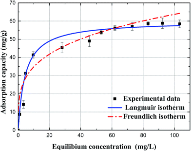 | ||
| Fig. 8 Adsorption isotherms of fluoride on Mg/Fe/La CHLc, the data were fitted with the Langmuir model and Freundlich model (pH, 6.8 ± 0.1; temperature, 35 °C, reaction time, 10 h). | ||
As showed in Fig. 8 and Table 3, the experiment data was in better agreement with the Langmuir model than the Freundlich model for fluoride adsorption on the Mg/Fe/La CHLc in water according to the R2, and the calculated value of qm (qe,cal, 59.98 mg g−1) from Langmuir model was close to the experimental adsorption capacity value (qe,exp, 58.79 mg g−1). In addition, the Langmuir constant, b, with a positive value, indicated that the adsorption of fluoride on the adsorbent was a favorable adsorption system.
| Isotherm | Parameter | Value |
|---|---|---|
| Langmuir | qm (mg g−1) | 59.98 |
| b (L mg−1) | 0.2217 | |
| R2 | 0.9806 | |
| Freundlich | KF (mg1−1/n L1/n g−1) | 19.04 |
| n | 0.2621 | |
| R2 | 0.8774 |
It was noted that the synthetic adsorbent Mg/Fe/La CHLc had a higher adsorption capacity than most of other adsorbents reported, such as carbon-based,13,37 alumina-based,12,38 other metal oxide14,39 and layered double hydroxide32,40 materials (listed in Table 4). Although the adsorption capacity of some adsorbents like La modified seaweed was higher than that of Mg/Fe/La CHLC, the reaction time was longer and the preparation method was more complicated.41 It was suggested that The Mg/Fe/La CHLc is a potential new material as an adsorbent for F removal in terms of higher adsorption capacity or shorter operation time.
| Adsorbents | pH | qe (mg g−1) | Equilibrium time | References |
|---|---|---|---|---|
| Bone char | 7–7.5 | 4.81 | 6000 min | 37 |
| Single-walled carbon nanotubes | 5 | 2.83 | 30 min | 13 |
| Mesoporous alumina | 3 | 8.25 | 150 min | 38 |
| Hierarchical alumina microspheres | 5.5 | 49.4 | 60 min | 12 |
| Fe–Al oxide-GO composite | 7 | 27.75 | 120 min | 39 |
| Mg–Al–La hydrous oxide | 7 | 41.746 | 40 min | 14 |
| ZnCr3–NO3–LDH | 6.8 | 31 | 120 min | 40 |
| Li–Al–LDH | 6–7 | 46.53 | 40 min | 32 |
| La modified seaweed | 7 | 94.34 | 240 min | 41 |
| Mg/Fe/La CHLc | 6.8 | 59.34 | 100 min | This study |
3.3 Adsorption mechanism
To further understand the adsorption mechanism of F on Mg/Fe/La CHLc in water, the samples before and after fluoride adsorption were further investigated using SEM, N2 adsorption–desorption, FT-IR and XPS analytical technique.From Fig. 3c, it was found that the sheets of Mg/Fe/La CHLc-F became more outstretched and the morphology look like petal shaped, which was similar to the Mg/Fe/La HLc. This phenomenon can be descripted as the fluoride ions penetrating into the aperture of the sheets or adsorbed on the interlayer domain of Mg/Fe/La CHLc, which leads to the expansion of the platelet and the crystal structure reconstruction. The BET surface area of Mg/Fe/La CHLc after adsorption decreased from 59.3 m2 g−1 to 27.9 m2 g−1, while the pore volume decreased from 0.347 cm3 g−1 to 0.249 cm3 g−1 (Table 1). This phenomenon was due to that the fluoride effectively adsorbed onto the Mg/Fe/La CHLc surface, indicating that surface adsorption played an important role during the fluoride adsorption by the hierarchically porous Mg/Fe/La CHLc.
The FT-IR spectra of the adsorbent before (b) and after fluoride adsorption (c) were given in Fig. 2. In comparison with virgin material, the Mg/Fe/La CHLc after adsorption of fluoride appeared a sharp peak at 3696 cm−1, meanwhile, the OH group shifted and decreased. The results suggested that OH group involved in the fluoride adsorption reaction, which is consistent with the mechanism of the Mg/Fe/La mixed oxide for fluoride removal.15 The peak at 856 cm−1 (Fig. 3b), which was attributed to the La–O bond vibration, decreased after adsorption and a new peak 1384 cm−1 (Fig. 3c) appeared, indicating that interaction occurs between La–O band and fluoride in the adsorption process,42 the specific mechanism of La for fluoride removal is further analysis by the XPS technique as follows.
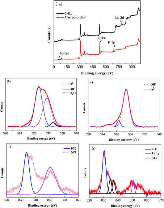
XPS survey spectra and high-resolution XPS spectra of O1s, La 3d of Mg/Fe/La CHLc before and after fluoride loading were conducted to further study the mechanisms of fluoride adsorption on Mg/Fe/La CHLc as shown in Fig. 9. It can be seen a new peak at 684.53 eV appeared after adsorption of fluoride, indicating that fluoride was effectively adsorbed onto the adsorbent, which matched the results of relative atoms amounts (%) listed in the Table 5. The high-resolution spectra of the O1s and La 3d for the Mg/Fe/La CHLc before and after F adsorption in water were shown in Fig. 9b–e. The O1s can be deconvoluted into three components at about 529.35, 531.65 and 533.35 eV, assigning to O2−, –OH and H2O, respectively.43 The peaks of position O1s shifted to lower binding energy after fluoride adsorption, indicating that relevant interactions occurred between the Mg/Fe/La CHLc and fluoride ion. In addition, the relative area ratio of O2− decreased from 54.17% to 8.36%, whereas the percentage of –OH increased from 42.13% to 91.64% (Table 6). This can be interpreted as the state of oxygen changing from O2− to –OH during the rehydration process. As shown in Fig. 9(d) and (e), the intensity and relative area ratio of 3d3 was markedly decreased after adsorption; meanwhile, two peaks appeared at 834.7 and 837.0 eV, which attributed to the LaF3.
| Atomic ratios (%) | O | C | F | Others |
|---|---|---|---|---|
| Mg/Fe/La CHLc | 51.18 | 19.13 | 0 | 29.69 |
| Mg/Fe/La CHLc-F | 43.29 | 20.57 | 5.71 | 30.43 |
| Sample | Peak | Binding energy (eV) | Percent (%) |
|---|---|---|---|
| Mg/Fe/La CHLc | O2− | 529.35 | 54.17 |
| –OH | 531.65 | 42.13 | |
| Mg/Fe/La CHLc-F | O2− | 528.6 | 8.36 |
| –OH | 530.65 | 91.64 |
From the above analysis, the mechanism for fluoride removal by Mg/Fe/La CHLc was explained as follows in detail:
The containing carbonates and hydroxyl in the interlayer of Mg/Fe/La HLc lost and layered double hydroxide decomposes into mixed metal oxides by thermal treatment (eqn (7)). The Mg/Fe/La CHLc can be rehydrated and incorporate fluoride ion in the interlayer to rebuild the original structure (eqn (8)). The fluoride ion incorporated into the interlayer of the Mg/Fe/La CHLc by rebuilding of the original layered structure, called ‘memory effect’ of hydrotalcite, which was in accordance with the SEM results.
 | (7) |
 | (8) |
The active component of lanthanum oxide on the Mg/Fe/La CHLc presented complexation with hydroxyl during the rehydration process (eqn (9)). Due to that the hydroxyl compounds of lanthanum has strong affinity for fluoride, a complexation occurred between fluoride ion and lanthanum (eqn (10)). Moreover, fluoride and hydroxyl have similar hydrated ionic radius, which resulted in the competition between fluoride and hydroxyl (eqn (11)). It can be interpreted the surface complexation and ion exchange coordinated to lanthanum immobilized on Mg/Fe/La CHLc.
| M − (La2O3)nLa2O3 + 3H2O → M − (La2O3)n2La(OH)3 | (9) |
| M − (La2O3)n2La(OH)3 + 4F− → M − (La2O3)n2La(OH)F2 + 4OH− | (10) |
| M − (La2O3)n2La(OH)F2 + 2F− → M − (La2O3)n2LaF3 + 2OH− | (11) |
Therefore, the adsorption of fluoride on the Mg/Fe/La CHLc was resulted from the chemisorption from the complexation of fluoride in water with the lanthanum on the surface of Mg/Fe/La CHLc, and also the surface adsorption by the porous structure and interlayer adsorption due to the “memory effect” of hydrotalcite.
3.4 Desorption and regeneration
To reduce the cost, environmental pollution and assess the reusability of the Mg/Fe/La CHLc, desorption and regeneration performances for re-use of the adsorbent were investigated. Desorption of the used Mg/Fe/La CHLc was performed in 0.1 M Na2CO3 solution and separated by filtration, then calcined in the muffle furnace to regenerate the Mg/Fe/La CHLc. The adsorption capacity at different regeneration cycles were conducted up to five times and the results were shown in Fig. 10. The value of regeneration cycle 0 corresponds to adsorption amount of fresh Mg/Fe/La CHLc. With the increasing regeneration times, the adsorption capacity showed a slight decrease and then reached a plateau after 4 times regeneration. After 5 times of desorption–regeneration cycle, the adsorption capacity of fluoride still achieved a value as high as 5.9 mg g−1. In addition, it was also found that the adsorbent without calcination after Na2CO3 desorption can also showed a defluoridation performance, however, at a very low value (data not shown). This suggested that CO32− can replace the fluoride ion in the interlayer during the rehydration process, and re-build the structure of Mg/Fe/La HLc. Therefore, the Mg/Fe/La CHLc used as an adsorbent for defluoridation is relatively reversible and can be effectively regenerated via Na2CO3 desorption.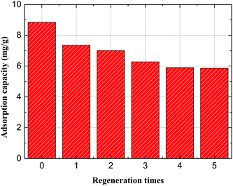 | ||
| Fig. 10 Regeneration behaviors of Mg/Fe/La CHLc by 0.1 M Na2CO3 (adsorbent dosage, 0.5 g L−1; initial fluoride concentration, 5.2 mg L−1; temperature, 35 °C; reaction time, 8 h). | ||
4. Conclusions
(1) In this work, the Mg/Fe/La CHLc material was synthesized through a facile one-step hydrothermal method and calcination at 600 °C. The Mg/Fe/La CHLc has shown a high adsorption capacity to fluoride in water, and could be easily regenerated with an aqueous Na2CO3 solution, indicating that it could be a potential and effective adsorbent for removing fluoride from water.(2) In the Mg/Fe/La HLc, the element of lanthanum played a significant role for the adsorption of fluoride in water.
(3) The adsorption of fluoride on the Mg/Fe/La CHLc in water might be attributed to the chemisorption due to the complexation of fluoride in water with the lanthanum on the surface of Mg/Fe/La CHLc, besides of the surface adsorption and interlayer adsorption due to the “memory effect” of hydrotalcite.
(4) The adsorption followed the Langmuir isotherm and fitted to the kinetics of pseudo-second-order model the maximum adsorption capacity was 60 mg g−1 for fluoride.
Acknowledgements
The financial supports for this work from the National Natural Science Foundation of China under the project No. 51474167, No. 51604207 and No. 51674183 are gratefully acknowledged.References
- J. A. Camargo, Chemosphere, 2003, 50, 251–264 CrossRef PubMed.
- M. G. Sujana, H. K. Pradhan and S. Anand, J. Hazard. Mater., 2009, 161, 120–125 CrossRef CAS PubMed.
- C. M. Kanno, R. L. Sanders, S. M. Flynn, G. Lessard and S. C. B. Myneni, Environ. Sci. Technol., 2014, 48, 5798–5807 CrossRef CAS PubMed.
- N. C. Lu and J. C. Liu, Sep. Purif. Technol., 2010, 74, 329–335 CrossRef CAS.
- L. H. Velazquez-Jimenez, R. H. Hurt, J. Matos and J. R. Rangel-Mendez, Environ. Sci. Technol., 2014, 48, 1166–1174 CrossRef CAS PubMed.
- Z. Amor, B. Bariou, N. Mameri, M. Taky, S. Nicolas and A. Elmidaoui, Desalination, 2001, 13, 215–223 CrossRef.
- L. A. Richards, M. Vuachère and A. I. Schäfer, Desalination, 2010, 261, 331–337 CrossRef CAS.
- P. Wu, L. Xia, M. Dai, L. Lin and S. Song, Colloids Surf., A, 2016, 502, 66–73 CrossRef CAS.
- S. Chatterjee and S. De, Sep. Purif. Technol., 2014, 125, 223–238 CrossRef CAS.
- A. Bhatnagar, E. Kumar and M. Sillanpää, Chem. Eng. J., 2011, 171, 811–840 CrossRef CAS.
- O. Kazak, A. Tor, I. Akin and G. Arslan, RSC Adv., 2016, 6, 86673–86681 RSC.
- N. Xu, Z. Liu, Y. Dong, T. Hong, L. Dang and W. Li, Ceram. Int., 2016, 42, 15253–15260 CrossRef CAS.
- M. H. Dehghani, G. A. Haghighat, K. Yetilmezsoy, G. Mckay, B. Heibati, I. Tyagi, S. Agarwal and V. K. Gupta, J. Mol. Liq., 2016, 216, 401–410 CrossRef CAS.
- Z. Hussain, D. Li, X. Li and J. Kang, RSC Adv., 2015, 5, 43906–43916 RSC.
- J. Wang, D. Kang, X. Yu, M. Ge and Y. Chen, Chem. Eng. J., 2015, 264, 506–513 CrossRef CAS.
- S. Miyata, Clays Clay Miner., 1980, 28, 50–56 CAS.
- J. Fan, Z. Xu and S. Zheng, J. Hazard. Mater., 2007, 139, 175–177 CrossRef CAS PubMed.
- A. Elhalil, S. Qourzal, F. Z. Mahjoubi, R. Elmoubarki, M. Farnane, H. Tounsadi, M. Sadiq, M. Abdennouri and N. Barka, Emerging Contaminants, 2016, 2, 42–48 CrossRef.
- K. Tomohito, O. Jumpei and Y. Toshiaki, J. Hazard. Mater., 2015, 293, 54–63 CrossRef PubMed.
- T. Kameda, J. Oba and T. Yoshioka, J. Environ. Manage., 2017, 188, 58–63 CrossRef CAS PubMed.
- J. Das, P. B. Sairam, N. Baliarsingh and K. M. Parida, J. Colloid Interface Sci., 2007, 316, 216–223 CrossRef CAS PubMed.
- X. J. Zhang, G. S. Wang, W. Q. Cao, Y. Z. Wei, J. F. Liang, L. Guo and M. S. Cao, ACS Appl. Mater. Interfaces, 2014, 6, 7471–7478 CAS.
- B. Kebede, A. Beyene, F. Fufa, M. Megersa and M. Behm, Appl. Water Sci., 2016, 6, 57–65 CrossRef CAS.
- D. Tang and G. Zhang, Chem. Eng. J., 2016, 283, 721–729 CrossRef CAS.
- J. Q. Chen, D. H. Yang, Y. Wei, J. H. Jiang, A. B. Ma and D. Song, Mater. Sci. Forum, 2015, 814, 118–124 CrossRef.
- Y. Zhou, C. Yu and Y. Shan, Sep. Purif. Technol., 2004, 36, 89–94 CrossRef CAS.
- S. Zhang, Y. Lu, X. Lin, X. Su and Y. Zhang, Appl. Surf. Sci., 2014, 303, 1–5 CrossRef CAS.
- K. Shimada, T. Shimoda, H. Kokusen and S. Nakano, Talanta, 2005, 66, 80–85 CrossRef CAS PubMed.
- X. L. Wu, L. Wang, C. L. Chen, A. W. Xu and X. K. Wang, J. Mater. Chem., 2011, 21, 17353–17359 RSC.
- S. Fu, G. Fan, L. Yang, F. Li, S. Fu, G. Fan and L. Yang, Electrochim. Acta, 2015, 152, 146–154 CrossRef CAS.
- W. Xiang, G. Zhang, Y. Zhang, D. Tang and J. Wang, Chem. Eng. J., 2014, 250, 423–430 CrossRef CAS.
- T. Zhang, Q. Li, H. Xiao, H. Lu and Y. Zhou, Ind. Eng. Chem. Res., 2012, 51, 11490–11498 CrossRef CAS.
- T. Wu, L. Mao and H. Wang, RSC Adv., 2015, 5, 23246–23254 RSC.
- D. Kang, X. Yu, S. Tong, M. Ge, J. Zuo, C. Cao and W. Song, Chem. Eng. J., 2013, 228, 731–740 CrossRef CAS.
- L. Lv, J. He, M. Wei, D. G. Evans and X. Duan, J. Hazard. Mater., 2006, 133, 119–128 CrossRef CAS PubMed.
- R. Bîrjega, O. D. Pavel, G. Costentin, M. Che and E. Angelescu, Appl. Catal., A, 2005, 288, 185–193 CrossRef.
- E. M. Nigri, A. Bhatnagar and S. D. F. Rocha, J. Cleaner Prod., 2016, 142, 3558–3570 CrossRef.
- S. G. Lanas, M. Valiente, E. Aneggi, A. Trovarelli, M. Tolazzi and A. Melchior, RSC Adv., 2016, 6, 42288–42296 RSC.
- S. Kanrar, S. Debnath, P. De, K. Parashar, K. Pillay, P. Sasikumar and U. C. Ghosh, Chem. Eng. J., 2016, 306, 269–279 CrossRef CAS.
- P. Koilraj and S. Kannan, Chem. Eng. J., 2013, 234, 406–415 CrossRef CAS.
- Y. Yu, C. Wang, X. Guo and C. J. Paul, J. Colloid Interface Sci., 2015, 441, 113–120 CrossRef CAS PubMed.
- W. Zhang, J. Fu, G. Zhang and X. Zhang, Chem. Eng. J., 2014, 251, 69–79 CrossRef CAS.
- L. Po-I, C. Li-Ching, H. Chia-Hua, S. Hsin, L. Teh-Ming, H. Ren-Yang, C. Min-Chao and C. C. M. Ma, J. Colloid Interface Sci., 2014, 446, 352–358 Search PubMed.
| This journal is © The Royal Society of Chemistry 2017 |

