DOI:
10.1039/C7RA04288D
(Paper)
RSC Adv., 2017,
7, 33671-33679
One-step synthesis of composite material MWCNT@BiVO4 and its photocatalytic activity
Received
16th April 2017
, Accepted 27th June 2017
First published on 3rd July 2017
Abstract
In this research, a composite material (MWCNT@BiVO4) was prepared using a one step hydrothermal method. The prepared composite material was characterized by energy-dispersive X-ray analysis, X-ray diffraction, scanning electron microscopy, EDS, UV-Vis diffuse-reflectance spectroscopy, electron spin resonance (ESR), X-ray photoelectron spectroscopy, and photoluminescence spectroscopy. The scanning electron microscopic images showed that MWCNTs were successfully embedded into BiVO4. MWCNT@BiVO4 showed a strong visible-light absorption capacity, high efficiency for electron–hole separation, and excellent stability. The degradation test of RhB was conducted under visible light irradiation. Compared with BiVO4 (K = −0.05657) and P25 (K = −0.03227), MWCNT@BiVO4 (K = −0.11894) realized the highest removal ratio of Rhodamine B (RhB) under visible light irradiation, therefore, MWCNT@BiVO4 might be promoted to practical applications. The stability of MWCNT@BiVO4 was also verified via recycling and reusing experiments. After 5 cycles, MWCNT@BiVO4 could still maintain the removal rate of RhB at 95.96%. In addition, this paper deduced the growth mechanism of MWCNT@BiVO4 and the degradation mechanism of RhB, proving that MWCNT@BiVO4 can be used in future practices.
1. Introduction
Since the titania (TiO2) electrode was found to be an effective photocatalyst for the decomposition of water in the early 1970s, nanoscale semiconductor-based photocatalysis has become a frontier science with rapid progress.1 With years of exploration, scientists found that existing photocatalytic technologies cannot effectively utilize and convert solar energy. In recent years, researchers have made attempts to adjust the energy band structure of semi-conductor photocatalysts, and have successfully prepared new visible photocatalysts, such as CaIn2O4,2 Bi2WO6,3 AgAlO2,4 InVO4,5 BiVO4,6 etc. Among them, BiVO4 is the most representative one, which has attracted extensive attention for its narrowed energy gap,41 higher chemical stability, strong redox ability, and non-toxic and environmentally friendly features.7–9 However, BiVO4 also has several shortcomings, such as weak adsorption capacity of target substances and easy recombination of photon-generated carriers. Therefore, it is necessary to further improve the visible photocatalytic activity of BiVO4.10
Generally, the modification methods of BiVO4 can be generally categorized into doping modification42 and compounding modification.11,12 The difficulty of doping modification is the realization of quantitative doping, as we know that over-doping could cause electron–hole recombination.13 Moreover, the high cost of noble metal doping14 as well as the toxicity of doping elements15 should also be taken into consideration. In contrast, the compositing modification enjoys advantages of controllability and easy operation.16 Through combining BiVO4 with other photocatalysts,17 heterojunction between BiVO4 and other semiconductors can be formed, which can improve the separation efficiency between electrons and holes and thus enhance the photocatalytic activity of bismuth. The composite photocatalysts include BiVO4/CeO2,43 Ag3PO4/InVO4/BiVO4,18 QD-RGO/InVO4/BiVO4,19 BiVO4/Bi2O2CO3,20 Pt/RuO2/BiVO4,21 Cu2O/BiVO4,22 InVO4/BiVO4,23 three-layer composite photocatalyst BiVO4–TiO2–BiVO4,44 etc. The electron–hole recombination of BiVO4 can be greatly reduced by compositing BiVO4 with other semiconductors or conductors.
As an advanced material with regular pipe network structure, carbon nanotubes (CNTs) can act as an ideal photocatalyst carrier for its good electrical conductivity, high chemical stability and strong adsorption capacity.24,25 During the preparation of composite material, introducing CNTs into BiVO4 can enhance the adsorption and enrichment capacity of BiVO4 upon organic matters. Moreover, the CNTs, with excellent electron conversion ability, can enhance the transmission and promote the separation of photon-generated carriers, so as to improve the photo-quantum efficiency of BiVO4. Researches on BiVO4/Bi2WO6/multi-walled carbon nanotube (MWCNT) nanocomposites,45 single wall carbon nanotube (SWCNT)/BiVO4,46 and CNT–BiVO4 (ref. 47) have been conducted for enhancing BiVO4 performance. However, it is indeed a difficulty to composite CNTs with semiconductor materials effectively, tightly, and easily.
To overcome the shortcomings of BiVO4 and the difficulties in the process of compositing CNTs with BiVO4, this research adopted one-step hydrothermal method to embed multi-walled carbon nanotubes (MWCNT) into BiVO4 and successfully prepared composite material MWCNT@BiVO4. The CNTs were tightly composited with BiVO4 semiconductor via a simple and effective method, just like that many “hands” were formed on BiVO4, so as to tightly grasp pollutants. Many “evacuation” passageways were established inside of BiVO4, so that the electron–hole pairs can be effectively separated and inhibited from being recombined. What's more, CNTs can provide more active sites owe to its larger specific surface area. Various characterization results showed that the modification material enjoyed excellent photo properties. The results of photocatalysis degradation experiments showed that as-prepared composite material had a significantly higher visible adsorption capacity, higher degradation capacity, and greatly increased kinetic constant of degradation rate for RhB. The recycle experiment results showed that such composite material enjoyed high stability. The growth mechanism and degradation mechanism of such composite material were deduced in this research, which is of guiding effect for its practical application and production. The as-prepared composite material could be applied into visible photocatalysis field.
2. Experimental section
2.1 Materials and reagents
This experiment involved analytically pure chemicals, including multi-walled carbon nanotube (MWCNT) solution (mass fraction of 10%, purity ≥ 99.85%, length 5–10 μm, diameter 10–40 nm, dispersed by 5% polyvinylpyrrolidone K-30 (PVP), Shanghai HuaYi Company, China), bismuth nitrate (Bi(NO3)3·5H2O, Chengdu Area of the Industrial Development Zone Xinde Mulan, Chongqing, China), sodium hydroxide powder (NaOH, Chongqing Chuandong Chemical Company, Chongqing, China), nitric acid (HNO3, Chengdu Area of the Industrial Development Zone Xinde Mulan, Chengdu, China), ammonium metavanadate (NH4VO3, Chongqing Chuandong Chemical Company, Chongqing, China), P25 (Shanghai strong Chemical Reagent Co., Ltd., Shanghai, China), Rhodamine B (RhB, Tianjin Guangfu Fine Chemical Research Institute, Tianjin, China).
2.2 Synthesis of BiVO4 and MWCNT@BiVO4
In preparation of BiVO4, first dissolve 2 mmol Bi(NO3)·5H2O with 4 mL of 4 mol L−1 HNO3 and 50 mL of deionized water, and then keep stirring the system for 30 min before resulting in solution called solution A. On the other hand, dissolve 2 mmol NH4VO3 with 4 mL of 2 mol L−1 NaOH, and then keep stirring the system for 30 min before producing solution B. After that, solution A and B were mixed, then transferred into a 100 mL of Teflon-lined autoclave to be sealed and heated at 180 °C for 16 h before cooling to room temperature. Subsequently, centrifuging treatment was conducted to obtain raw product, which was then washed with distilled water and ethanol for six times, and dried under vacuum condition overnight at 60 °C for 12 h. Finally, the product was calcined in muffle furnace at 400 °C for 3 h before obtaining final product. In contrast, to synthesize MWCNT@BiVO4, 2 mg of MWCNT solution (mass fraction 10%, dispersed by 5% PVP) was added to solution A. The remaining processes are identical as the synthesis process of BiVO4.
2.3 Characterization
The crystal structures of as-prepared samples were characterized by X-ray diffraction (XRD) under Cu K radiation using a Rigaku D/Max2500pc diffractometer (Tokyo, Japan), with scanning angle of 2θ varying from 10° to 70° and the scanning rate being set to 4° min−1. A Zeiss AURIGA field emission microscope (EHT = 10 kV; Zeiss, Oberkochen, Germany) was adopted to obtain scanning electron microscopy (SEM) images under a laser source of Ar+. Energy-dispersive X-ray analysis (EDS) was conducted during SEM measurements. The surface chemical environments of prepared samples were investigated by X-ray photoelectron spectra (XPS) using a PHI5000 (Kanagawa Prefecture, Japan) Versa Probe system with monochromatic Al K X-rays. Hitachi U-3010 (Tokyo, Japan) UV-Vis spectrophotometer was used to carry out UV-Vis diffuse-reflectance spectroscopy (UV-Vis DRS). The photoluminescence (PL) spectra of as-prepared photocatalysts were acquired by a Hitachi F-7000 (Tokyo, Japan) spectrometer with excitation wavelength of 280 nm. Electron spin resonance (ESR, JES FA200, Tokyo, Japan) measurement was carried out by mixing the samples in a 50 mM DMPO solution tank (wherein the aqueous dispersion was for DMPO–˙OH while methanol dispersion was for DMPO–˙O2−). It is worth noting that all experiments were conducted at room temperature.
2.4 Evaluation of photocatalytic activity and stability of MWCNT@BiVO4 composites
The photocatalytic activities of as-prepared samples could be evaluated through photodegradation of RhB under visible irradiation at room temperature. In the experiment, 0.20 g of catalyst was first added into a 250 mL beaker containing 200 mL of 5 mg L−1 RhB aqueous solution, and then mixed solution was subjected to magnetic stirring for 30 min in the dark to reach good dispersion and adsorption–desorption equilibrium between catalyst and dye. The experimental solution was placed 350 mm away from a 500 W Xe lamp (with <420 nm cut-off UV filter) which acted as a visible light source. The solution was collected every 1 h, and then subjected to 10![[thin space (1/6-em)]](https://www.rsc.org/images/entities/char_2009.gif) 000 rpm centrifugation for removing all catalysts. Through measuring the absorbance of the solutions at 552 nm using a spectrophotometer, the concentration of remaining dye was monitored. For comparison, photocatalytic experiments were also conducted with pure BiVO4, MWCNT@BiVO4, P25, and no catalyst, respectively. To investigate the stability of prepared samples, the solution after photocatalysis degradation was centrifuged at 10
000 rpm centrifugation for removing all catalysts. Through measuring the absorbance of the solutions at 552 nm using a spectrophotometer, the concentration of remaining dye was monitored. For comparison, photocatalytic experiments were also conducted with pure BiVO4, MWCNT@BiVO4, P25, and no catalyst, respectively. To investigate the stability of prepared samples, the solution after photocatalysis degradation was centrifuged at 10![[thin space (1/6-em)]](https://www.rsc.org/images/entities/char_2009.gif) 000 rpm to collect products, and then these products were recycled 5 times before characterization.
000 rpm to collect products, and then these products were recycled 5 times before characterization.
3. Results and discussion
3.1 XRD pattern analysis
Among several crystal forms of BiVO4, only the monoclinic crystal BiVO4 can effectively absorb visible light.26 Fig. 1 show the XRD patterns of MWCNT, BiVO4 and MWCNT@BiVO4. It can be observed that all primary diffraction peaks of the BiVO4 XRD patterns are in good consistence with monoclinic BiVO4 (JCPDS no. 14-0688). All the peaks of the BiVO4 are agree with the planes of (110), (011), (−121), (121) etc. of the monoclinic BiVO4, and no other impure peaks emerge. This reveals that the highly pure monoclinic BiVO4 has been successfully prepared by a one-step hydrothermal method.27 According to the diffractogram of MWCNT@BiVO4, the new peak are not presented in BiVO4 but in the XRD patterns of MWCNT.28 The newly peak appears in the composite is pertained to the characteristic peak of plane (111) of MWCNT. And all of the left peaks are match with those in the pure BiVO4. This indicates that MWCNT has been successfully composited with BiVO4.
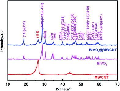 |
| | Fig. 1 XRD patterns of MWCNT, BiVO4 and MWCNT@BiVO4. | |
3.2 Analysis of morphology and composition based on SEM, EDS and HRTEM
Fig. 2a and b show the SEM images of BiVO4 and MWCNT@BiVO4, respectively. Fig. 2c is the partial enlarged detail of Fig. 2b. From Fig. 2c, it can be observed that the pure BiVO4 is a porous thin slice with smooth surface, while MWCNT@BiVO4 is a sphere with MWCNT embedded on rough surface, which is more suitable for the occurrence of chemical reaction. It can be clearly seen that MWCNT is tightly embedded with BiVO4. According to the EDS of MWCNT@BiVO4 in Fig. 2d–i as well as EDS line of MWCNT@BiVO4 in Fig. 3, it can be known that sample MWCNT@BiVO4 consists of Bi, O, V and C, which is consistent with the XRD and XPS results shown in Fig. 1 and 4b, respectively. Some CNTs are embedded inside of BiVO4, while some are exposed on surface of BiVO4. The HRTEM of MWCNT@BiVO4 is shown in the Fig. 2j–l, it can be seen clearly that the MWCNT and BiVO4 are in good combination. This arrangement is beneficial for sample to take advantages of the excellent adsorption capacity and the large specific surface area of CNTs, so as to provide more active points. In addition, such arrangement is suitable for the electrons inside of BiVO4 to be discharged via CNTs, which is conductive to the separation of electron–hole pairs. Therefore, MWCNT@BiVO4 is expected to show good photocatalytic activity.
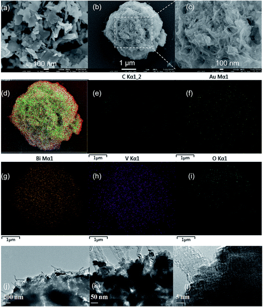 |
| | Fig. 2 SEM images of as-synthesized BiVO4 (a), MWCNT@BiVO4 (b and c), EDS of MWCNT@BiVO4 (d–i) after sputtering Au on silicon slice, HRTEM of MWCNT@BiVO4 (j–l). | |
 |
| | Fig. 3 Scanning of EDS line of MWCNT@BiVO4: (a) SEM image, (b) element content distributions of Bi, V, C and O, (c) EDS spectra. | |
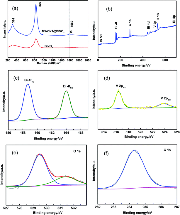 |
| | Fig. 4 (a) Raman spectra of BiVO4 and MWCNT@BiVO4, (b–f) XPS of MWCNT@BiVO4: (b) survey spectra, (c) Bi 4f5/2 and Bi 4f7/2 peaks, (d) V 2p3/2 and V 2p1/2 peaks, (e) O 1s peak, and (f) C 1s peaks. | |
3.3 Analysis of chemical states through Raman spectrum and XPS
We investigated the chemical states and composition of as-prepared samples according to Raman spectrum and XPS. Raman spectrum peak is sensitively related with short-range ordered structure of the photocatalyst.29 According to Raman spectrum, we can know material information such as local structure, crystallinity, and electronic properties.30 As can be seen in Fig. 4, the peaks at 827 and 324 cm−1 are associated with the typical vibrations of monoclinic BiVO4. The peak at 324 cm−1 is ascribed to bending vibration and asymmetric stretching vibration of VO43−. It can be seen that the intensity of Raman peak of MWCNT@BiVO4 is stronger than that of BiVO4. The Raman spectra also reveal that the PVP and MWCNT have little effect on the short-range symmetry of the VO43− tetra-hedra.48 In addition, the Raman peak may also be affected by the morphology of the sample.49 On the other hand, the disappearance of the 712 cm−1 peaks may because of that the samples were hydrothermally prepared.13 The Raman peak at 827 cm−1 is mainly caused by two V–O stretching vibrations of different orders. According to Fig. 4a, there is a typical peak at 1580 cm−1 in the Raman spectrum of MWCNT. This typical peak is correlated to the G band of the ordered structure of carbon nanotubes.31
XPS analysis was conducted to investigate the chemical states of as-prepared samples. The spectra within the range of 0–700 eV are shown in Fig. 4b. It can be observed that the composite material consists of O, V, Bi, and C. The binding energy of non-oxygenated ring C is corrected to 284.6 eV. Fig. 4c shows that the binding energies Bi 4f7/2 and Bi 4f5/2 are 158.8 and 164.1 eV, respectively.32 According to Fig. 4d, the peaks at binding energies of 523.9 (V 2p1/2) and 516.4 eV (V 2p3/2) are ascribed to the split signal of V 2p, and the V 2p peak is ascribed to V5+.33 According to Fig. 4e, the samples have XPS signals of O 1s at 529.7 eV and 532.7 eV, which is mainly due to the O2− anions in the BiVO4 crystallites. The Raman spectrum and XPS are consistent with the XRD and EDS.
3.4 Characterization of optical properties based on UV-Vis DR, PL, ESR
Fig. 5a shows the UV-Vis diffuse reflectance spectra of as-prepared samples. It can be observed that BiVO4 and WMCNT@BiVO4 have strong absorption capacities both in the ultraviolet region and in the visible region. The UV absorption capacities can be ascribed to the band transition from O 2p to V 3d, while the visible-light absorption is associated with the transition from valence band to V 3d conduction band.34 According to the split-level absorption spectrum, we can find that the electronics migration is not an impure state migration.35 Both adsorption intensity and adsorption range of WMCNT@BiVO4 are improved. The absorption band is expanded from 525 nm to 630 nm. Therefore, it can be concluded that the optical properties of WMCNT@BiVO4 is better than that of pure BiVO4.
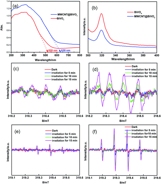 |
| | Fig. 5 (a) UV-vis spectra. (b) PL spectra at room temperature. (c–f) Electron spin resonance spectroscopy: (c) DMPO–˙O2− for BiVO4. (d) DMPO–˙O2− for WMCNT@BiVO4. (e) DMPO–˙OH for BiVO4, (f) DMPO–˙OH for WMCNT@BiVO4. | |
PL spectrum can be influenced by the transferring, migration, and separation efficiency of photogenerated charge carriers in semiconducting materials.36 The PL intensity is determined by the photocatalytic activity. PL measurement was carried out to investigate the effect of MWCNT on the photocatalytic process. As shown in Fig. 5b, the PL spectrum of MWCNT@BiVO4 is compared with that of BiVO4 under the excitation wavelength of 280 nm. It can be found that the PL peak intensity of MWCNT@BiVO4 is significant higher, which reveals that MWCNT is beneficial for separation of electron–hole pair.
The active radicals during the photocatalysis process was detected by electron spin resonance spectroscopy.37 In this research, we captured ˙OH (DMPO–˙OH) and ˙O2− (DMPO–˙O2) using 5,5-dimethyl-1-pyrroline-N-oxide (DMPO). According to Fig. 5c–f, we can find that the ˙O2− and ˙OH− signal peaks appear after visible irradiation for 15 min. However, no signal peaks of the ˙O2− and ˙OH appear in dark condition. This indicates that the ˙OH and ˙O2− are generated under visible irradiation.38 The signal of MWCNT@BiVO4 is significantly stronger than that of BiVO4, which indicates that photogenerated carriers resulted from MWCNT embedding further enhance the production of active species.
3.5 Evaluation of photocatalytic activity and chemical stability of as-prepared photocatalyst based on degradation of RhB and analysis of its recycling stability
Fig. 6a shows the photocatalytic activities of samples under visible irradiation for 7 hours. In contrast, the self-degradation of RhB (with no catalyst) was also estimated. Results showed that the self-degradation rate of RhB after visible irradiation for 7 h was about 1.79%. In contrast, the degradation rates of RhB with MWCNT@BiVO4, BiVO4, P25 were 96.90%, 46.47%, and 25.70%, respectively. MWCNT@BiVO4 (K = −0.11894) realized the highest degradation rate of RhB, followed by BiVO4 (K = −0.05657) and P25 (K = −0.03227). MWCNT@BiVO4 has excellent photocatalytic performance for its high visible light absorption capacity, high separation efficiency of photogenerated charge carriers, large specific surface area, and large quantity of active sites. The photocatalytic activity of P25 under visible irradiation was limited as it can only absorb UV light. The removal rate of RhB is mainly dependent on the light adsorption and the optical sensibilization of RhB.39
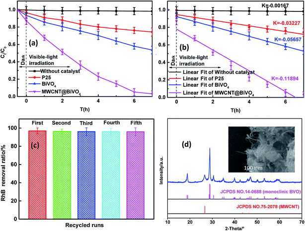 |
| | Fig. 6 (a) Degradation rates of RhB with various catalysts under visible irradiation; (b) linear fitting of data from photocatalytic reaction with reaction rate constant, K. (c) Photocatalytic degradation of RhB using MWCNT@BiVO4 after 5 recycles; (d) SEM image and XRD patterns of MWCNT@BiVO4 after 5 recycles. | |
The chemical stability is key parameter, which greatly affects application performance of photocatalysts. The RhB removal rate using recycled MWCNT@BiVO4 under visible light irradiation is shown in Fig. 6c. It can be observed that the degradation rate of RhB tends to be stable after five cycles. Through repeated tests, it can be known that the MWCNT@BiVO4 can be easily recycled by simple filtration, and the finally removal rate maintains at 95.96%, which is pretty stable. According to Fig. 6d, it can be observed that the phase structure of the sample remains unchanged, which indicates that the MWCNT@BiVO4 is not easily to be photodecomposed. The high chemical stability of MWCNT@BiVO4 is of great importance to its practical application and modification.
3.6 Postulated formation mechanism of MWCNT@BiVO4
The formation of specific crystal morphology can be accounted by the directional coalescence mechanism. Therefore, a highly ordered superstructure can be formed by directional self-assembly of primary particles. Following the growth mechanism shown in Scheme 1, PVP is adsorbed and intertwined on MWCNT, and thus the surface energy of surface energy is reduced, so that MWCNT can be dispersed and prevented from being reunited (see the first step 1 in the Scheme 1); after adding Bi(NO3)3, Bi3+ is selectively adsorbed on the surface of the PVP. There exists coordination interaction between metal ions and carbonyl group of PVP (see the step 2 in the Scheme 1);40 after addition of NH4VO3, VO3− will react with Bi3+ on PVP, resulting in seed crystals (see the step 3 in the Scheme 1); then transferring the seed crystals into high-temperature hydrothermal reactor, the seed crystals gradually grow and develop (see step 4 in the Scheme 1); finally, BiVO4 is ripened and PVP is calcined in muffle furnace at 400 °C (see step 5 in the figure).
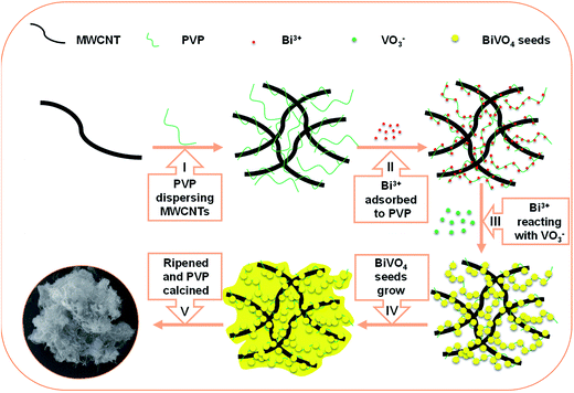 |
| | Scheme 1 Postulated growth mechanism of the MWCNT@BiVO4. | |
3.7 Degradation mechanism of RhB with photocatalysts
Scheme 2 is the postulated degradation mechanism of RhB with MWCNT@BiVO4. According to the enlarged detail of the Scheme 2, the RhB molecules are first absorbed on the surface of MWCNT@BiVO4, and then some of RhB molecules are transferred into excited state (RhB*) under visible-light irradiation. After that, the electrons are introduced from the RhB* into the MWCNT. Meanwhile, electrons of BiVO4 can be transferred from VB to CB under visible-light excitation, leaving holes in the VB. Moreover, the electrons on the surface of BiVO4 can be trapped and transferred quickly by the MWCNT. The electrons on MWCNT can react with O2 to produce ˙O2− radicals and ˙OH radicals. It is worth noting that electron hole can also produce some hydroxyl radicals. Lastly, RhB+ and RhB are degraded by ˙O2−, ˙OH or holes. The MWCNT, as electron-mediators in this process, conductive to the separation and transferring of injected electrons. In addition, the MWCNT also acts as adsorption fuel as well as significant base providing reactive sites. The whole set of reaction processes can be summarized as follows:| | |
RhB + visible light → RhB*
| (R1) |
| | |
RhB* + MWCNT@BiVO4 → MWCNT@BiVO4 (e−) + RhB+
| (R2) |
| | |
BiVO4 + visible light → BiVO4 (h+ + e−)
| (R3) |
| | |
BiVO4 (e−) + MWCNT → BiVO4 + MWCNT (e−)
| (R4) |
| | |
MWCNT (e−) + O2 → MWCNT + ˙O2−
| (R5) |
| | |
˙O2− + H2O → ˙OH + OH− + O2
| (R6) |
| | |
˙OH, ˙O2− or h+ + RhB or RhB+ → degradation products
| (R8) |
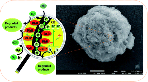 |
| | Scheme 2 Degradation mechanism of RhB with MWCNT@BiVO4. | |
4. Conclusions
In this paper, a composite material MWCNT@BiVO4 was prepared using one-step hydrothermal method. The prepared samples were analyzed by various characterization methods. In the synthesis process, MWCNT was well embedded inside of the BiVO4, while BiVO4 maintained monoclinic structure. Due to the embedding of MWCNT, the visible light absorption range was expanded, the adsorption intensity was improved, and the separation of carriers was significantly enhanced. The photocatalytic activities of as-prepared samples were estimated through the degradation rate of RhB under visible light irradiation. Results showed that the photocatalytic activity of MWCNT@BiVO4 was the highest. Moreover, MWCNT@BiVO4 can maintain substantial photocatalytic activity even after 5 recycles. The prepared composite material MWCNT@BiVO4 enjoyed excellent chemical stability. The formation process of such composite material can be accounted by directional growth mechanism. The photo degradation mechanism of MWCNT@BiVO4 was also deduced in this paper. This new material prepared in this research is expected to have a promising application in practice.
Acknowledgements
Financial support from the Science and Technology Innovation Special Projects of Social Undertakings and Livelihood Support, Chongqing (cstc2016shmszx20009), the Science and Technology Project of Chongqing Education Commission (KJ1500604), the graduate scientific research and innovation foundation of Chongqing, China (CYB16008), the Chongqing Research Program of Basic Research and Frontier Technology (cstc2015jcyjA20013) and the 111 Project (B13041) is gratefully acknowledged.
References
- R. Daghrir, P. Drogui and D. Robert, Ind. Eng. Chem. Res., 2013, 52, 3581–3599 CrossRef CAS.
- J. Gou, J. Wang, B. Yu and D. Zhang, J. Nanosci. Nanotechnol., 2016, 16, 3973–3976 CrossRef CAS PubMed.
- R. Rahimi, S. Pordel and M. Rabbani, J. Nanostruct. Chem., 2016, 6, 191–196 CrossRef CAS.
- K. C. Bhamu and K. R. Priolkar, Mater. Chem. Phys., 2017, 190, 114–119 CrossRef CAS.
- D. S. Lee and Y. W. Chen, J. CO2 Util., 2015, 10, 1–6 CrossRef.
- C. Laberty-Robert, S. Hilliard, D. Friedrich, H. Strubb, S. Kressman and V. Artero, ChemPhotoChem, 2017, 6, 273–280 Search PubMed.
- P. Longchin, P. Pookmanee, S. Satienperakul, S. Sangsrichan, R. Puntharod, V. Kruefu, W. Kangwansupamonkon and S. Phanichphant, Integr. Ferroelectr., 2016, 175, 18–24 CrossRef CAS.
- T. S. Sinclair, B. M. Hunter, J. R. Winkler, H. B. Gray and A. M. Müller, Mater. Horiz., 2014, 2, 330–337 RSC.
- I. Khan, S. Ali, M. Mansha and A. Qurashi, Ultrason. Sonochem., 2017, 36, 386–392 CrossRef CAS PubMed.
- L. Chen, D. Meng, X. Wu, A. Wang, J. Wang, Y. Wang and M. Yu, J. Phys. Chem. C, 2016, 120, 18548–18559 CAS.
- Y. Ma, F. L. Formal, A. Kafizas, S. R. Pendlebury and J. R. Durrant, J. Mater. Chem. A, 2015, 3, 20649–20657 CAS.
- K. T. Woo, P. Yuan, G. A. Galli and C. Kyoung-Shin, Nat. Commun., 2015, 6, 8769 CrossRef PubMed.
- C. Yin, S. Zhu, Z. Chen, W. Zhang, J. Gu and D. Zhang, J. Mater. Chem. A, 2013, 1, 8367–8378 CAS.
- Z. F. Huang, L. Pan, J. J. Zou, X. Zhang and L. Wang, Nanoscale, 2014, 6, 14044–14063 RSC.
- C. Karunakaran and S. Kalaivani, Mater. Sci. Semicond. Process., 2014, 27, 352–361 CrossRef CAS.
- M. Zhong, T. Hisatomi, Y. Kuang, J. Zhao, M. Liu, A. Iwase, Q. Jia, H. Nishiyama, T. Minegishi and M. Nakabayashi, J. Am. Chem. Soc., 2015, 137, 5053–5060 CrossRef CAS PubMed.
- P. Ju, P. Wang, B. Li, H. Fan, S. Ai, D. Zhang and Y. Wang, Chem. Eng. J., 2014, 236, 430–437 CrossRef CAS.
- X. Lin, X. Guo, W. Shi, F. Guo, G. Che, H. Zhai, Y. Yan and Q. Wang, Catal. Commun., 2015, 71, 21–27 CrossRef CAS.
- X. Lin, Y. Wang, J. Zheng, C. Liu, Y. Yang and G. Che, Dalton Trans., 2015, 44, 19185–19193 RSC.
- P. Madhusudan, J. Ran, J. Zhang, J. Yu and G. Liu, Appl. Catal., B, 2011, 110, 286–295 CrossRef CAS.
- F. Lin, D. Wang, Z. Jiang, Y. Ma, J. Li, R. Li and C. Li, Energy Environ. Sci., 2012, 5, 6400–6406 CAS.
- E. Aguilera-Ruiz, U. M. García-Pérez, M. D. L. Garza-Galván, P. Zambrano-Robledo, B. Bermúdez-Reyes and J. Peral, Appl. Surf. Sci., 2015, 328, 361–367 CrossRef CAS.
- G. Feng, W. Shi, L. Xue, Y. Xu, G. Yu and G. Che, Sep. Purif. Technol., 2015, 141, 246–255 CrossRef.
- J. Du, S. Pei, L. Ma and H. M. Cheng, Adv. Mater., 2014, 28, 12384–12392 Search PubMed.
- S. N. Habisreutinger, T. Leijtens, G. E. Eperon, S. D. Stranks, R. J. Nicholas and H. J. Snaith, Nano Lett., 2014, 14, 5561–5568 CrossRef CAS PubMed.
- Y. Lu, H. Shang, F. Shi, C. Chao, X. Zhang and B. Zhang, J. Phys. Chem. Solids, 2015, 85, 44–50 CrossRef CAS.
- R. Huo, X. L. Yang, Y. Q. Liu and Y. H. Xu, Mater. Res. Bull., 2017, 88, 56–61 CrossRef CAS.
- D. Zhao, W. Zong, Z. Fan, S. Xiong, M. Du, T. Wu, Y. W. Fang, F. Ji and X. Xu, CrystEngComm, 2016, 18, 9007–9015 RSC.
- H. M. Zhang, J. B. Liu, H. Wang, W. X. Zhang and H. Yan, J. Nanopart. Res., 2008, 10, 767–774 CrossRef CAS.
- J. B. Liu, H. Wang, S. Wang and H. Yan, Mater. Sci. Eng., B, 2003, 104, 36–39 CrossRef.
- M. Zhang, C. Shao, X. Li, P. Zhang, Y. Sun, C. Su, X. Zhang, J. Ren and Y. Liu, Nanoscale, 2012, 4, 7501–7508 RSC.
- H. Li, Y. Sun, B. Cai, S. Gan, D. Han, L. Niu and T. Wu, Appl. Catal., B, 2015, 170–171, 206–214 CrossRef CAS.
- H. Huang, L. Liu, Y. Zhang and N. Tian, RSC Adv., 2014, 5, 1161–1167 RSC.
- B. Xie, H. Zhang, P. Cai, R. Qiu and Y. Xiong, Chemosphere, 2006, 63, 956–963 CrossRef CAS PubMed.
- T. Xiong, F. Dong and Z. Wu, RSC Adv., 2014, 4, 56307–56312 RSC.
- S. Selvarajan, A. Suganthi, M. Rajarajan and K. Arunprasath, Powder Technol., 2017, 307, 203–212 CrossRef CAS.
- J. Zhang, Y. Lu, L. Ge, C. Han, Y. Li, Y. Gao, S. Li and H. Xu, Appl. Catal., B, 2017, 204, 385–393 CrossRef CAS.
- T. Wu, J. Long, Z. Fan, M. Du, S. Xiong, D. Zhao, F. Ji, H. E. Qiang, Y. Zeng and X. Xu, CrystEngComm, 2016, 18, 6471–6482 RSC.
- Q. Wang, X. Chen, K. Yu, Y. Zhang and Y. Cong, J. Hazard. Mater., 2013, 246–247, 135–144 CrossRef CAS PubMed.
- Q. Gong, X. Qian, X. Ma and Z. Zhu, Cryst. Growth Des., 2006, 6, 1821–1825 CAS.
- M. Yao, M. Liu, L. Gan, F. Zhao, X. Fan, D. Zhu, Z. Xu, Z. Hao and L. Chen, Colloids Surf., A, 2013, 433, 132–138 CrossRef CAS.
- M. Yao, L. Gan, M. Liu, P. K. Tripathi, Y. Liu and Z. Hu, J. Mater. Eng. Perform., 2015, 24, 2359–2367 CrossRef CAS.
- N. Wetchakun, S. Chaiwichain, B. Inceesungvorn, K. Pingmuang, S. Phanichphant, A. I. Minett and J. Chen, ACS Appl. Mater. Interfaces, 2012, 4, 3718–3723 CAS.
- M. Wang, W. Li, Y. Zhao, S. Gu, F. Wang, H. Li, X. Liu and C. Ren, RSC Adv., 2016, 6, 75482–75490 RSC.
- L. Lin, D. Yu, W. Wang, P. Gao, K. Bu and B. Liu, Mater. Lett., 2016, 185, 507–510 CrossRef CAS.
- Z. Khan, S. Bhattu, S. Haram and D. Khushalani, RSC Adv., 2014, 4, 17378–17381 RSC.
- X. Zhou, J. Yu, Y. Zhang, D. Yu and W. Lu, Rare Met., 2011, 30, 199–202 CrossRef CAS.
- B. Liu, Z. Li, S. Xu, X. Ren, D. Han and D. Lu, J. Phys. Chem. Solids, 2014, 75, 977–983 CrossRef CAS.
- A. Galembeck and O. L. Alves, Thin Solid Films, 2000, 365, 90–93 CrossRef CAS.
|
| This journal is © The Royal Society of Chemistry 2017 |
Click here to see how this site uses Cookies. View our privacy policy here.  Open Access Article
 ae,
Wenwen Wangb,
Yaofang Sunad,
Zihong Fanc,
Mao Duae,
Qian Zhangad,
Fangying Jiad and
Xuan Xu*ae
![[thin space (1/6-em)]](https://www.rsc.org/images/entities/char_2009.gif) 000 rpm centrifugation for removing all catalysts. Through measuring the absorbance of the solutions at 552 nm using a spectrophotometer, the concentration of remaining dye was monitored. For comparison, photocatalytic experiments were also conducted with pure BiVO4, MWCNT@BiVO4, P25, and no catalyst, respectively. To investigate the stability of prepared samples, the solution after photocatalysis degradation was centrifuged at 10
000 rpm centrifugation for removing all catalysts. Through measuring the absorbance of the solutions at 552 nm using a spectrophotometer, the concentration of remaining dye was monitored. For comparison, photocatalytic experiments were also conducted with pure BiVO4, MWCNT@BiVO4, P25, and no catalyst, respectively. To investigate the stability of prepared samples, the solution after photocatalysis degradation was centrifuged at 10![[thin space (1/6-em)]](https://www.rsc.org/images/entities/char_2009.gif) 000 rpm to collect products, and then these products were recycled 5 times before characterization.
000 rpm to collect products, and then these products were recycled 5 times before characterization.


