 Open Access Article
Creative Commons Attribution 3.0 Unported Licence
A facile conversion of a Ni/Fe coordination polymer to a robust electrocatalyst for the oxygen evolution reaction
Lieyuan Huangb,
Xingbo Ge *ab and
Shuai Dongb
aState Key Laboratory of Oil and Gas Reservoir Geology and Exploitation, Southwest Petroleum University, Chengdu 610500, P. R. China. E-mail: xbge@swpu.edu.cn; Tel: +86-28-83037337
bThe Center of New Energy Materials and Technology, School of Chemistry and Chemical Engineering, Southwest Petroleum University, Chengdu 610500, China
First published on 27th June 2017
Abstract
Cost-efficient, active, and durable electrocatalysts are highly desired to facilitate the oxygen evolution reaction (OER) for water splitting. On the basis of a Ni hexacyanoferrate (NiHCF) Prussian blue-type coordination polymer, a facile route was developed to fabricate robust Ni/Fe composites for the OER in alkaline electrolyte. The obtained catalysts were characterized by SEM, XRD, FTIR, EDS and XPS methods, and the catalytic activity was evaluated by the electrochemical technique. The Ni/Fe catalyst, which was identified as mixed Ni/Fe oxides, afforded an OER onset overpotential of 310 mV and a Tafel slope of ∼44 mV per decade in alkaline medium. The Ni/Fe composite also exhibits excellent durability in the electrocatalysis process. No obvious degradation of the OER catalytic density was observed during the cyclic voltammetry (CV) process.
Introduction
The growing demand for energy and the increasing concerns about environmental pollution from fossil fuels are stimulating intense research interest in energy conversion and storage from alternative sustainable energy sources.1 Hydrogen, as a clean and sustainable energy carrier, has attracted tremendous interest around the world. “Hydrogen economy” has emerged as a fascinating new field.2 Photochemical or electrochemical splitting of water to form hydrogen and oxygen offers a possible means for storing energy obtained from intermittent sources such as the sun and wind.3 The sluggish kinetics of the oxygen evolution reaction (OER), accompanied with the four electron and four proton transfer, has been regarded as a major bottleneck in the overall water splitting process.4 To facilitate the OER process, considerable efforts have been devoted to the development of effective electrocatalysts during the past few decades.5 While RuO2 and IrO2 have been identified as the most active catalysts for the OER,6–8 their high cost restricts their commercial applications. Recently, transition-metal-based composites manifested comparable OER activity, and thus are considered as alternative catalysts with low cost and earth-abundant storage.9,10Ni/Fe-based composites have been known as active OER catalysts since 1980s,11 and renewed interest has been witnessed in recent years on developing Ni/Fe-based materials for better activity and stability.12–16 Many approaches, including electrodeposition, hydrothermal synthesis method, and photochemical metal–organic deposition etc., have been exploited to construct Ni/Fe oxides/or hydroxides as advanced OER catalysts. For example, the cathodically electrodeposited Ni/Fe alloy films, would be oxidized to oxides/or hydroxides layers under the OER condition (or just in the air), serving as OER active electrodes.12,17–19 Adopting this electrodeposition strategy, McCrory et al. evaluated the OER activity of a series of heterogeneous electrocatalysts and found Ni/Fe-based composites stood out among all non-precious metal catalysts in concentrated alkaline conditions.8,20 The chemical-hydrothermal or co-deposition method was also extensively reported to synthesize Ni/Fe oxides films,21 nanoparticles,22–24 Ni/Fe double hydroxide hybrids,25–29 and their high OER activity have been demonstrated. Recently, by combining photochemical metal–organic deposition and post annealing treatment, Smith et al. has successfully prepared amorphous Ni/Fe oxide thin films, exhibiting a superior OER activity compared to other Ni or Fe based electrocatalysts.30,31 Qiao et al. have in situ grown the nitrogen doped NiFe double layered hydroxide nanolayers on 3D nickel foam, thus achieved an extremely high OER catalytic activity.32 In spite of these progress, new catalysts and synthetic methods should be explored to fabricate more candidates for OER.
Prussian blue-type coordination polymers (PBs) are a type of versatile materials, which were extensively applied in magnetism,33,34 electrochromism,35 biosensors,36 catalysis37,38 and sodium-ion batteries.39,40 Due to its porosity, well-controlled morphology and compositions, PBs can be recognized as promising candidates for water oxidation catalysts. Very recently, PBs were served as precursors to prepare nanoporous metal oxide materials, which exhibited promising water oxidation activity in both neutral and basic media.41–43 Since PBs have three-dimensional open architecture, and taking account of the high activity of Ni/Fe composites, it would be worth addressing a detailed research on Ni hexacyanoferrates (NiHCF) as new efficient OER catalyst.
Herein, on the basis of NiHCF, we reported a facile route to fabricate active Ni/Fe composite as efficient OER electrocatalyst in alkaline medium. It was found that the structure and properties of the Ni/Fe composite could be tuned by varying the annealing condition. The optimized Ni/Fe composites exhibit enhanced activity and durability for OER.
Experimental section
Materials
All chemicals were purchased in analytical grade from Chengdu Kelong Chemical Reagent Company, and used without further purification.Synthesis of NiHCF and Ni/Fe composites
The NiHCF was first fabricated by codeposition. Typically, nickel salt aqueous solution (10 mM) and ferricyanide aqueous solution (10 mM) were prepared by dissolving NiCl2·6H2O and K3[Fe(CN)6] in ultrapure water, respectively. Then the two solutions were mixed in beaker by dropwise adding the as-prepared K3[Fe(CN)6] solution (40 mL) into NiCl2 solution (40 mL) at 30 °C under vigorous stirring, immediately forming an obvious slurry. The formed slurry was maintained at 30 °C for 1 h and then aged for 24 h at room temperature without any interruption. The precipitate was separated by centrifugation at 3000 rpm for 20 min, then washed with ultrapure water for three times. The NiHCF was finally obtained by drying the precipitates at 50 °C in air for 12 h.The fabrication of Ni/Fe composites was realized by annealing the NiHCF precursor under various temperatures, ranging from 150 to 600 °C. All of the precursors were annealed under the selected temperature for 2 h with a ramp of 10 °C min−1. Hereafter, the samples made by annealing treatment would be named as “involved metals + heated temperature”. For instance, NiHCF annealed at 300 °C would be expressed as “Ni/Fe-300”.
Characterization
The crystalline structures of as-prepared materials were investigated by powder X-ray diffraction (XRD). The XRD patterns with diffraction intensity versus 2θ were detected by an X'Pert PRO MPD X-ray diffractometer (PANalytical B.V.) using Cu-Kα as radiation source. The scanning rate was kept at 5° min−1. The morphology and elemental compositions of the as-synthesized materials were analyzed using ZEISS EV0 MA15 scanning electron microscope (SEM) coupled with energy-dispersive X-ray spectroscopy (EDS). The Fourier transform infrared (FTIR) spectra were measured on a FTIR spectrometer (WQF520, Beijing Rayleigh Analytical Instrument Corporation) at room temperature. The surface electronic state and composition of materials were studied using an X-ray photoelectron spectrometer (XPS) (ESCALAB 250, ThermoFisher Scientific USA) equipped with a monochromated Al K X-ray source.Electrochemical measurements
Electrochemical experiments were performed on a CHI 600D electrochemistry workstation (CH Instrument, Shanghai, China) with a standard three-electrode configuration in 0.1 M KOH at room temperature. A Pt wire and Ag/AgCl (sat.) electrode were used as counter and reference electrodes, respectively. In brief, the catalyst (5 mg) was dispersed in 1 mL water/isopropanol solution (3![[thin space (1/6-em)]](https://www.rsc.org/images/entities/char_2009.gif) :
:![[thin space (1/6-em)]](https://www.rsc.org/images/entities/char_2009.gif) 1 v/v) containing 100 μL Nafion solution (DuPont 520, 5 wt%) by sonicating for 30 min to form a homogeneous ink. Then 4 μL of the catalyst ink (containing 20 μg of catalyst) was loaded onto an indium tin oxide (ITO) with a catalyst loading of ∼0.10 mg cm−2, and then used as the working electrode. Prior to catalysts coating, the ITO was sonicated sequentially in 1 M NaOH aqueous solution, ultrapure water, and absolute ethanol. The electrochemical capacitances of the electrodes were determined using cyclic voltammetry (CV). Electrochemical impedance spectroscopy (EIS) measurements were conducted in 1 M KOH with the amplitude potential of 5 mV, and the frequency scan range was from 0.1 Hz to 100 kHz at 1.573 V vs. RHE. All the potentials in this article were converted to reversible hydrogen electrode (RHE) potential according the equation E(RHE) = E(Ag/AgCl) + 0.059 pH + 0.197 V. The overpotentials (η) were calculated by the equation η = E(RHE) − 1.23 V.
1 v/v) containing 100 μL Nafion solution (DuPont 520, 5 wt%) by sonicating for 30 min to form a homogeneous ink. Then 4 μL of the catalyst ink (containing 20 μg of catalyst) was loaded onto an indium tin oxide (ITO) with a catalyst loading of ∼0.10 mg cm−2, and then used as the working electrode. Prior to catalysts coating, the ITO was sonicated sequentially in 1 M NaOH aqueous solution, ultrapure water, and absolute ethanol. The electrochemical capacitances of the electrodes were determined using cyclic voltammetry (CV). Electrochemical impedance spectroscopy (EIS) measurements were conducted in 1 M KOH with the amplitude potential of 5 mV, and the frequency scan range was from 0.1 Hz to 100 kHz at 1.573 V vs. RHE. All the potentials in this article were converted to reversible hydrogen electrode (RHE) potential according the equation E(RHE) = E(Ag/AgCl) + 0.059 pH + 0.197 V. The overpotentials (η) were calculated by the equation η = E(RHE) − 1.23 V.
The turnover frequency (TOF) was calculated according to equation: TOF = j × A/(4 × F × m), where j is the current density obtained at overpotential of 400 mV in A cm−2, A is the surface area of the electrode, F is the Faraday efficiency (96![[thin space (1/6-em)]](https://www.rsc.org/images/entities/char_2009.gif) 485 C mol−1) and m is the number of moles of the Ni2+ deposited onto the electrodes.
485 C mol−1) and m is the number of moles of the Ni2+ deposited onto the electrodes.
Results and discussion
The crystalline structures of the NiHCF and annealed samples were characterized by XRD, as shown in Fig. 1. All diffraction peaks of NiHCF are identical to the reported experimental patterns which ascribe to Prussian blue-type coordination polymers,37 indicating a pure Ni hexacyanoferrate phase. As annealing temperature increases, these diffraction peaks of NiHCF weaken gradually, and disappear at the temperature of 300 °C. Meanwhile, the appearance of six diffraction peaks at 30.4°, 35.7°, 37.3°, 43.4°, 57.6° and 63.1° for samples that annealed upon 300 °C could be assigned to NiFe2O4 (JCPDF 10-0325) and NiO (JCPDF 44-1159). The peak at 44.4° for both Ni/Fe-300 and Ni/Fe-450 samples might be derived from the (200) plane of Fe3O4 phase (JCPDF 28-0491). After annealed at 600 °C, all of the detectable diffraction peaks belong to NiFe2O4 and NiO.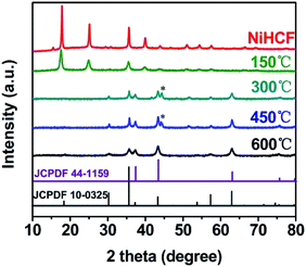 | ||
| Fig. 1 XRD patterns of the as-prepared Ni hexacyanoferrate (NiHCF) and the annealed samples. The peaks beneath “*” attribute to Fe3O4 (JCPDF 28-0491). | ||
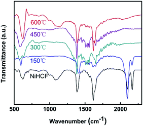
The chemical evolution of Ni/Fe samples were detected by FTIR spectroscopy, as shown in Fig. 2. Two absorption bands at 2165 cm−1 and 2097 cm−1 for both NiHCF and Ni/Fe-150 samples could be indexed to the CN stretching mode (Fe–CN–Ni) and the typical cyanide linkage isomerism pattern of NiHCF, respectively.33,37 These two absorption bands disappear at 300 °C, suggesting the decomposition of NiHCF. This observation is in line with the XRD results. Besides, the bending vibration appears at 1610 cm−1 could be ascribed to water molecular, and the bands ranging at 1000–1400 cm−1 can be assigned to M–O mode.44
The morphology and microstructure of the prepared catalysts were observed by SEM. Fig. 3 shows the SEM images of NiHCF, Ni/Fe-300 and Ni/Fe-600. All of the samples show an agglomerate of nanoparticles with diameter of 50–200 nm. EDS results suggest the atom ratio of Ni/Fe in the Ni/Fe composites is ca. 1.2, slightly higher than the initial ratio of Ni2+/[Fe(CN)6]3− (1![[thin space (1/6-em)]](https://www.rsc.org/images/entities/char_2009.gif) :
:![[thin space (1/6-em)]](https://www.rsc.org/images/entities/char_2009.gif) 1).
1).
 | ||
| Fig. 3 SEM images of the (a) as-prepared NiHCF, (b) NiHCF annealed at 300 °C and (c) 600 °C. The scale bars are 500 nm. | ||
The chemical and electronic states of Ni/Fe composites were investigated by XPS (Fig. 4). The XPS survey spectra (Fig. 4a) show the expected photoelectron peaks due to Ni, Fe, and O elements in three samples. The N 1s peak is only detected in NiHCF, which could be ascribed to Fe–CN–Ni group (FTIR).
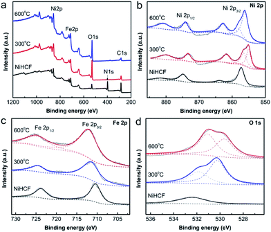 | ||
| Fig. 4 XPS spectra of the as-prepared NiHCF and the annealed samples: (a) survey, (b) Ni 2p, (c) Fe 2p and (d) O 1s. | ||
Additionally, the Ni 2p (Fig. 4b) and Fe 2p (Fig. 4c) spectra of NiHCF could be assigned to Ni hexacyanoferrate,45 thus confirmed the synthesis of Ni–Fe Prussian blue analogue. The two fitted peaks located at 855.2 eV and 856.5 eV for Ni 2p3/2 of Ni/Fe-300 (Fig. 4b) could be assigned to Ni2+ in NiFe2O4 and NiO, respectively,46,47 which consistent with the XRD results. For Ni/Fe-600 sample, the Ni 2p3/2 peaks shift to 856.1 eV and 857.8 eV, indicating the change of surface electronic state. The Fe 2p spectrum (Fig. 4c) of Ni/Fe-300 presented two peaks at the binding energy of 711.2 eV and 724.4 eV, which belong to the Fe 2p3/2 and Fe 2p1/2 of Fe3+.48 These Fe 2p3/2 and Fe 2p1/2 peaks have positively shifted in Ni/F-600 sample. The shift of Ni 2p and Fe 2p peaks in Ni/Fe-600 sample might be relevant to the appearance of O vacancy in the composites, which could be identified by the O 1s XPS spectra. As shown in O 1s spectra (Fig. 4d), the symmetrical O 1s peak for NiHCF at binding energy of 532.4 eV could be assigned to chemisorbed oxygen species. The O 1s region of Ni/Fe-300 catalyst could be fitted to two individual peaks. The O 1s at 530.2 eV is typically for metal–oxygen bonds, and the 531.8 eV peak can be attributed to OH adsorbed groups. For Ni/Fe-600 sample, the O 1s peaks at the binding energy of 529.6 eV and 530.9 eV could be assigned to the lattice oxygen and oxygen vacancy, respectively.49,50 The difference of relative intensity of the two peaks in two samples indicates the changes of the structure and surface properties with the variation of the annealing temperature.
To evaluate the OER activity of the as-prepared catalysts, the Ni/Fe composites were loaded onto ITO electrodes and investigated using electrochemical CV technique in 0.1 M KOH (pH 13) electrolyte at a constant scan rate of 20 mV s−1. Fig. 5a show a group of iR-compensated CV curves of Ni/Fe catalysts. While bare ITO electrode is inactive towards OER, all the samples show obvious OER activity. For NiHCF, a pair of redox peaks clearly shows up at 1.16–1.23 V, which could be assigned to [Fe(CN)6]3−/[Fe(CN)6]4− couple in the coordination polymer. These redox peaks decrease in intensity with the annealing temperature, and disappear at Ni/Fe-300 sample, further verify the complete decomposition of the NiHCF polymer. Although annealing at 150 °C did not change the crystalline structure of NiHCF, Ni/Fe-150 sample exhibits enhanced OER activity. The highest electrocatalytic activity was observed on Ni/Fe-300, with an onset overpotential as low as 310 mV, and a further increase of the annealing temperature inversely results in a decrease of the OER activity. The potentials required for the current of 1 mA cm−2, 5 mA cm−2 and 10 mA cm−2 were used to further elaborate the OER catalytic activity of Ni/Fe catalysts. The Ni/Fe-300 achieves a small overpotential of 355 mV, 416 mV and 462 at 1 mA cm−2, 5 mA cm−2 and 10 mA cm−2, respectively. TOF was calculated to illustrate the intrinsic activity of Ni/Fe catalysts (Table 1). We have calculated TOF using the catalyst mass and composition. The TOF of Ni/Fe-300 at overpotential of 400 mV is 0.05 s−1, higher than other annealed samples and comparable to the N–Ni/Fe LDH reported previously.32 The significant improvement in the OER kinetics on Ni/Fe-300 is also demonstrated by the lower Tafel slope of 44 mV dec−1 at low overpotential compared to other samples (Fig. 5b). It is well accepted that a Tafel slope of ∼40 mV dec−1 indicating the rate-determining step (RDS) of the OER reaction is the second electron transfer step from the hydroxylated active site to form the oxide: M–OH + OH− = M–O + H2O + e−, where “M” denotes the active site. While a slope of 60 mV dec−1 indicates that the RDS is a chemical evolution of the unstable M–OH* to form more stable M–OH.51–53 The distinction of Tafel slope between NiHCF and Ni/Fe oxides suggests a different catalytic mechanism.
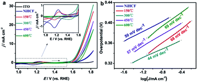 | ||
| Fig. 5 (a) iR-compensated CV curves and (b) Tafel plots of the as-prepared NiHCF and the annealed samples in 0.1 M KOH, the inset in (a) is a magnification of CVs from 0.96 V to 1.6 V (vs. RHE). | ||
| Sample | Electrolyte | η onset potential [mV] | η at 1 mA cm−2 [mV] | η at 5 mA cm−2 [mV] | η at 10 mA cm−2 [mV] | Turnover frequency (TOF) at η = 400 mV | Tafel slope [mV dec−1] | Reference |
|---|---|---|---|---|---|---|---|---|
| NiHCF/ITO | 0.1 M KOH | 364 | 453 | 572 | — | — | 50 | This work |
| Ni/Fe-150/ITO | 0.1 M KOH | 341 | 375 | 432 | 476 | 0.03 | 68 | This work |
| Ni/Fe-300/ITO | 0.1 M KOH | 310 | 355 | 416 | 462 | 0.05 | 44 | This work |
| Ni/Fe-450/ITO | 0.1 M KOH | 342 | 395 | 457 | 507 | 0.02 | 57 | This work |
| Ni/Fe-600/ITO | 0.1 M KOH | 370 | 413 | 478 | 532 | 0.01 | 69 | This work |
| MWCNTs/Ni(OH)2 | 0.1 M KOH | 322 | 373 | 435 | 474 | — | 87 | 54 |
| HU-NiCo2O4/GC | 0.1 M KOH | 316 | — | — | — | — | 51 | 55 |
| N–NiFe LDH | 0.1 M KOH | 210 | — | — | 230 | 0.05 | 35 | 32 |
| IrO2 | 0.1 M KOH | 300 | — | — | 350 | 0.03 | 23 | 32 |
| 2D N–NiFe LDH | 0.1 M KOH | 310 | — | — | 390 | 165 | 32 | |
| Co, N doped carbon | 0.1 M KOH | — | — | — | 350 | — | 83.3 | 56 |
| NG-NiCo | 0.1 M KOH | 350 | — | — | — | — | 614 | 57 |
| Fe6Ni10Ox | 1 M KOH | — | — | — | 286 | — | 48 | 22 |
| Ni0.69Fe0.31Ox/C | 1 M KOH | — | — | — | 280 | — | 30 | 24 |
| Ni2/3Fe1/3–GO | 1 M KOH | — | — | — | 230 | 42 | 28 | |
| CQD/NiFe-LDH | 1 M KOH | — | — | — | 235 | — | — | 29 |
| Ni–Co PBA | 1 M KOH | — | — | — | 380 | — | 50 | 43 |
The aforementioned results indicate that NiHCF could serve as a promising composite to fabricate active OER catalysts. The as-prepared Ni/Fe-300 afforded superior activity as an OER catalyst, with a lower onset overpotential and Tafel slope than that of the reported MWCNTs/Ni(OH)2 (ref. 54) and hollow urchin-like NiCo2O4 nanoparticle (Table 1).55 Actually, it's difficult to compare the activity of the catalysts prepared by diverse methods directly because of the distinct structure and thus the active surface area. Although the fabricated Ni/Fe catalyst is not as good as same well-studied Ni/Fe catalysts at current density of 10 mA cm−2, it could be compensated by further tailing the catalyst structure or using 3D porous substrate.
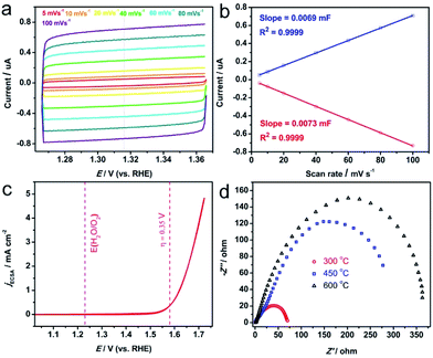
In order to compare the intrinsic activity of the Ni/Fe-300 catalyst with the reported results, the OER activity was also measured in 1 M KOH solution. The electrochemically active surface area (ECSA) was used to normalize the catalytic current density. The ECSA is estimated by determining the double-layer capacitance from CV according to the previous reports.8,20 Briefly, the potential is scanned in a nonfaradaic potential window (here is 1.266 V to 1.366 V vs. RHE) at varying scan rates (Fig. 6a). The obtained current plotted against the scan rate at 1.316 V (vs. RHE) gives a straight line (Fig. 6b). The slope of the line is assigned to the electrochemical double layer capacitance (Cdl). Herein, the Cdl adopted the average value of the slope of anodic and cathodic lines, and the ECSA is obtained by dividing Cdl with specific capacitance Cs (0.040 mF cm−2), which is found to be ∼0.1775 cm2. The ECSA normalized CV of Ni/Fe-300 is shown in Fig. 6c, the current density at η = 0.35 V for OER is ∼0.38 mA cm−2, which is superior to the NiOx (0.12 mA cm−2), NiCeOx (0.11 mA cm−2), NiCoOx (0.2 mA cm−2), NiCuOx (0.15 mA cm−2) and comparable to that of IrOx (0.4 mA cm−2).8 More benchmarking parameters of the recently reported catalysts could be found in Table 2. Further improvement of activity might be realized by using ideal supports such as graphene to well disperse the as-prepared catalysts.
The long-term stability of the Ni/Fe-300 catalyst towards the OER was also examined by the cycling and potentiostatic in 0.1 M KOH solution, Fig. 7 shows the OER polarization tests curves measured before and after 1000 CV cycles at a scan rate of 20 mV s−1. After the 1000 cycles, the Ni/Fe-300 catalyst shows a slight loss of current density compared with the initial cycle, indicating the Ni/Fe-300 catalyst is highly stable in a long-term electrochemical OER process. Besides, when biased potentiostatically at a overpotential of 334 mV on the electrode, the Ni/Fe-300 catalyst also afforded a relatively stable catalytic current density for 10 h consecutive electrolysis.
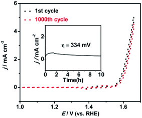 | ||
| Fig. 7 Durability test for the Ni/Fe-300 (NiHCF annealed at 300 °C) sample by CVs before and after 1000 cycles and the i–t curve (inset) at the overpotential of 334 mV in 0.1 M KOH solution. | ||
Based on the above experimental results and analysis, we could reasonably discuss the origin of the superior OER activity of the Ni/Fe-300 sample. As confirmed by XRD, FTIR and XPS spectra, the NiHCF is gradually decomposed into Ni/Fe oxides at high temperature, and the Ni/Fe-300 catalyst mainly consists of NiFe2O4 and NiO. Studies suggested that spinel nickel ferrite (NiFe2O4) with Ni2+ occupying the tetrahedral holes and Fe3+ occupying the octahedral holes plays a significant role in improving the oxygen evolution activity of the mixed metal oxide systems.58–60 Therefore, the enhancement of the OER catalytic activity of Ni/Fe-300 could be attributed to the formation of mixed NiFe2O4 dominated phase and the synergistic effect involved in the hybrids. Otherwise, the higher annealing temperature leads to higher resistance (Fig. 6d), which would hamper the electrontransfer and thus cause the inferior OER activity. The interaction effects between the Ni and Fe in the mixed metal oxides still in controversy and could be thoroughly investigated. Profoundly, the OER activity Ni/Fe binary and Ni/Fe/M ternary metal compounds and incorporating with supporting materials (such as nitrogen-doped carbon nanotubes and 3D graphene) are worthy of exploring in future researches.
Conclusions
In summary, we have demonstrated a facile route to convert NiHCF to an active Ni/Fe composite as efficient OER electrocatalyst in alkaline media. The structure, components, chemical states and OER catalytic performance of the composite were well-controlled by changing the annealing condition. The Ni/Fe-300, confirmed as mixed Ni/Fe oxides, exhibited best OER catalytic activity with onset overpotential of 310 mV and a Tafel slope of 44 mV dec−1. No obvious degradation of the OER catalytic activity of the Ni/Fe composites electrode during the CV measurements was observed. The results indicated that the metal hexacyanometallates are reliable precursors to fabricate high efficient OER catalysts, and could be easily extended to other mixed metal composites, thus offered a promising avenue to obtain OER catalysts with high efficiency and stability, which could potentially serve as electrocatalysts for (photo)electrochemical cells in water splitting application.Acknowledgements
This work was supported by the National Natural Science Foundation of China (21403174).References
- N. Armaroli and V. Balzani, Angew. Chem., Int. Ed., 2007, 46, 52–66 CrossRef CAS PubMed.
- T. R. Cook, D. K. Dogutan, S. Y. Reece, Y. Surendranath, T. S. Teets and D. G. Nocera, Chem. Rev., 2010, 110, 6474–6502 CrossRef CAS PubMed.
- A. J. Bard and M. A. Fox, Acc. Chem. Res., 1995, 28, 141–145 CrossRef CAS.
- M. W. Kanan and D. G. Nocera, Science, 2008, 321, 1072–1075 CrossRef CAS PubMed.
- J. Yang, D. Wang, H. Han and C. Li, Acc. Chem. Res., 2013, 46, 1900–1909 CrossRef CAS PubMed.
- Y. Zhang, E. C. Judkins, D. R. McMillin, D. Mehta and T. Ren, ACS Catal., 2013, 3, 2474–2478 CrossRef CAS.
- T. Nakagawa, N. S. Bjorge and R. W. Murray, J. Am. Chem. Soc., 2009, 131, 15578–15579 CrossRef CAS PubMed.
- C. C. L. McCrory, S. Jung, J. C. Peters and T. F. Jaramillo, J. Am. Chem. Soc., 2013, 135, 16977–16987 CrossRef CAS PubMed.
- A. Singh and L. Spiccia, Coord. Chem. Rev., 2013, 257, 2607–2622 CrossRef CAS.
- R. Subbaraman, D. Tripkovic, K.-C. Chang, D. Strmcnik, A. P. Paulikas, P. Hirunsit, M. Chan, J. Greeley, V. Stamenkovic and N. M. Markovic, Nat. Mater., 2012, 11, 550–557 CrossRef CAS PubMed.
- D. A. Corrigan, J. Electrochem. Soc., 1987, 134, 377–384 CrossRef CAS.
- M. W. Louie and A. T. Bell, J. Am. Chem. Soc., 2013, 135, 12329–12337 CrossRef CAS PubMed.
- D. Friebel, M. W. Louie, M. Bajdich, K. E. Sanwald, Y. Cai, A. W. Wise, M.-J. Cheng, D. Sokaras, T.-C. Weng, R. Alonso-Mori, R. C. Davis, J. R. Bargar, J. K. Nørskov, A. Nilsson and A. T. Bell, J. Am. Chem. Soc., 2015, 137, 1305–1313 CrossRef CAS PubMed.
- L. Trotochaud, S. L. Young, J. K. Ranney and S. W. Boettcher, J. Am. Chem. Soc., 2014, 136, 6744–6753 CrossRef CAS PubMed.
- M. Gong and H. Dai, Nano Res., 2015, 8, 23–39 CrossRef CAS.
- J. B. Gerken, S. E. Shaner, R. C. Massé, N. J. Porubsky and S. S. Stahl, Energy Environ. Sci., 2014, 7, 2376–2382 CAS.
- X. Li, F. C. Walsh and D. Pletcher, Phys. Chem. Chem. Phys., 2011, 13, 1162–1167 RSC.
- M. D. Merrill and R. C. Dougherty, J. Phys. Chem. C, 2008, 112, 3655–3666 CAS.
- K. H. Kim, J. Y. Zheng, W. Shin and Y. S. Kang, RSC Adv., 2012, 2, 4759–4767 RSC.
- C. C. L. McCrory, S. Jung, I. M. Ferrer, S. M. Chatman, J. C. Peters and T. F. Jaramillo, J. Am. Chem. Soc., 2015, 137, 4347–4357 CrossRef CAS PubMed.
- L. Trotochaud, J. K. Ranney, K. N. Williams and S. W. Boettcher, J. Am. Chem. Soc., 2012, 134, 17253–17261 CrossRef CAS PubMed.
- L. Kuai, J. Geng, C. Chen, E. Kan, Y. Liu, Q. Wang and B. Geng, Angew. Chem., Int. Ed., 2014, 53, 7547–7551 CrossRef CAS PubMed.
- D. Zhang, L. Meng, J. Shi, N. Wang, S. Liu and C. Li, Electrochim. Acta, 2015, 169, 402–408 CrossRef CAS.
- Y. Qiu, L. Xin and W. Li, Langmuir, 2014, 30, 7893–7901 CrossRef CAS PubMed.
- Y. Vlamidis, E. Scavetta, M. Gazzano and D. Tonelli, Electrochim. Acta, 2016, 188, 653–660 CrossRef CAS.
- X. Long, J. Li, S. Xiao, K. Yan, Z. Wang, H. Chen and S. Yang, Angew. Chem., Int. Ed., 2014, 126, 7714–7718 CrossRef.
- M. Gong, Y. Li, H. Wang, Y. Liang, J. Z. Wu, J. Zhou, J. Wang, T. Regier, F. Wei and H. Dai, J. Am. Chem. Soc., 2013, 135, 8452–8455 CrossRef CAS PubMed.
- W. Ma, R. Ma, C. Wang, J. Liang, X. Liu, K. Zhou and T. Sasaki, ACS Nano, 2015, 9, 1977–1984 CrossRef CAS PubMed.
- D. Tang, J. Liu, X. Wu, R. Liu, X. Han, Y. Han, H. Huang, Y. Liu and Z. Kang, ACS Appl. Mater. Interfaces, 2014, 6, 7918–7925 CAS.
- R. D. L. Smith, M. S. Prévot, R. D. Fagan, Z. Zhang, P. A. Sedach, M. K. J. Siu, S. Trudel and C. P. Berlinguette, Science, 2013, 340, 60–63 CrossRef CAS PubMed.
- R. D. L. Smith, M. S. Prévot, R. D. Fagan, S. Trudel and C. P. Berlinguette, J. Am. Chem. Soc., 2013, 135, 11580–11586 CrossRef CAS PubMed.
- S. Chen, J. Duan, P. Bian, Y. Tang, R. Zheng and S.-Z. Qiao, Adv. Energy Mater., 2015, 5, 1500936 CrossRef.
- H. Alamri, N. Ballot, J. Long, Y. Guari, J. Larionova, K. Kleinke, H. Kleinke and E. Prouzet, Chem. Mater., 2014, 26, 875–885 CrossRef CAS.
- M. Cao, X. Wu, X. He and C. Hu, Chem. Commun., 2005, 17, 2241–2243 RSC.
- K. Lee, A.-Y. Kim, J. H. Park, H.-G. Jung, W. Choi, H. Y. Lee and J. K. Lee, Appl. Surf. Sci., 2014, 313, 864–869 CrossRef CAS.
- S.-M. Chen and K.-T. Peng, J. Electroanal. Chem., 2003, 547, 179–189 CrossRef CAS.
- S. Pintado, S. G. Ferrón, E. C. Escudero-Adán and J. R. Galán-Mascarós, J. Am. Chem. Soc., 2013, 135, 13270–13273 CrossRef CAS PubMed.
- L. Zhang, L. Shi, L. Huang, J. Zhang, R. Gao and D. Zhang, ACS Catal., 2014, 4, 1753–1763 CrossRef CAS.
- M. J. Piernas-Muñoz, E. C. Castillo-Martínez, O. Bodarchuk, M. Armand and T. Rojo, J. Power Sources, 2016, 324, 766–773 CrossRef.
- L. Wang, J. Song, R. Qiao, L. A. Wray, M. A. Hossain, Y.-D. Chuang, W. Yang, Y. Lu, D. Evans, J.-J. Lee, S. Vail, X. Zhao, M. Nishijima, S. Kakimoto and B. G. Goodenough, J. Am. Chem. Soc., 2015, 137, 2548–2554 CrossRef CAS PubMed.
- J. Wei, Y. Feng, Y. Liu and Y. Ding, J. Mater. Chem. A, 2015, 3, 22300–22310 CAS.
- X. Li, L. Yuan, J. Wang, L. Jiang, A. I. Rykov, D. L. Nagy, C. Bogdán, M. A. Ahmed, K. Zhu, G. Sun and W. Yang, Nanoscale, 2016, 8, 2333–2342 RSC.
- L. Han, X.-Y. Yu and W. Lou, Adv. Mater., 2016, 28, 4601–4605 CrossRef CAS PubMed.
- L. Poul, N. Jouini and F. Fiévet, Chem. Mater., 2000, 12, 3123–3132 CrossRef CAS.
- S. Tricard, C. Costa-Coquelard, F. Volatron, B. Fleury, V. Huc, P.-A. Albouy, C. David, F. Miserque, P. Jeqou, S. Palacin and T. Mallah, Dalton Trans., 2012, 41, 1582–1590 RSC.
- N. S. Mclntyre and M. G. Cook, Anal. Chem., 1975, 47, 2208–2213 CrossRef.
- S. O. Grim, L. J. Matienzo and W. E. Swartz Jr, J. Am. Chem. Soc., 1972, 94, 5116–5117 CrossRef CAS.
- N. S. McIntyre and D. G. Zetaruk, Anal. Chem., 1977, 49, 1521–1529 CrossRef CAS.
- C. Solís, S. Somacescu, E. Palafox, M. Balaguer and J. M. Serra, J. Phys. Chem. C, 2014, 118, 24266–24273 Search PubMed.
- T. L. Barr, J. Phys. Chem., 1978, 82, 1801–1810 CrossRef CAS.
- F. J. Pérez-Alonso, C. Adán, S. Rojas, M. A. Peña and J. L. G. Fierro, Int. J. Hydrogen Energy, 2014, 39, 5204–5212 CrossRef.
- D. K. Bediako, C. Costentin, E. C. Jones, D. G. Nocera and J.-M. Savéant, J. Am. Chem. Soc., 2013, 135, 10492–10502 CrossRef CAS PubMed.
- Y. Surendranath, M. W. Kanan and D. G. Nocera, J. Am. Chem. Soc., 2010, 132, 16501–16509 CrossRef CAS PubMed.
- X. Zhou, Z. Zhang, Y. Ma and Y. Qu, J. Mater. Chem. A, 2014, 2, 11799–11806 CAS.
- J. Wang, T. Qiu, X. Chen, Y. Lu and W. Yang, J. Power Sources, 2014, 268, 341–348 CrossRef CAS.
- B. Bayatsarmadi, Y. Zheng, Y. Tang, M. Jaroniec and S.-Z. Qiao, Small, 2016, 12, 3703–3711 CrossRef CAS PubMed.
- S. Chen, J. Duan, M. Jaroniec and S.-Z. Qiao, Angew. Chem., Int. Ed., 2013, 52, 13567–13570 CrossRef CAS PubMed.
- A. A. Singh and R. N. Singh, Int. J. Hydrogen Energy, 2010, 35, 3243–3248 CrossRef.
- J. Landon, E. Demeter, N. İnoğlu, C. Keturakis, I. E. Wachs, R. Vasić, A. I. Frenkel and J. R. Kitchin, ACS Catal., 2012, 2, 1793–1801 CrossRef CAS.
- Y.-F. Li and A. Selloni, ACS Catal., 2014, 4, 1148–1153 CrossRef CAS.
| This journal is © The Royal Society of Chemistry 2017 |

