
 Open Access Article
 This Open Access Article is licensed under a
 Creative Commons Attribution 3.0 Unported Licence
Accordion-like graphene by a facile and green synthesis method reinforcing polyolefin nanocomposites†
Wensheng Gaoa,
Jiangong Li a,
Xiaojie Yana,
Bochao Zhub,
Junji Jiab,
Anping Huangb,
Kefeng Xieb and
Yongxiao Bai*a
a,
Xiaojie Yana,
Bochao Zhub,
Junji Jiab,
Anping Huangb,
Kefeng Xieb and
Yongxiao Bai*a
aMOE Key Laboratory for Magnetism and Magnetic Materials, Institute of Material Science and Engineering, Lanzhou University, Lanzhou 730000, PR China. E-mail: baiyx@lzu.edu.cn
bLanzhou Petrochemical Research Center, Petro China, Lanzhou 730000, PR China
First published on 15th June 2017
Abstract
Herein, accordion-like graphene with a large specific surface area, efficient reduction degree and designed functional groups was successfully synthesized via thermal expansion exfoliation of alkylated graphite oxide at relatively low temperature (below 170 °C) without any auxiliary equipment. This functional graphene (M-LTRGO) displayed an improved compatibility and interfacial interaction with polyolefin matrix. The graphene-reinforced polyolefin (including polypropylene and polyethylene) nanocomposites exhibited better mechanical strength and thermal stability than the neat and parallel graphene-reinforced polyolefin nanocomposites. The tensile breaking strength of random polypropylene (PPR) and linear low-density polyethylene (LLDPE) increased by 42.77% and 58.59%, respectively, after their incorporation at a loading amount of 0.5 wt%. Into M-LTRGO that is much more stronger than other graphene counterparts obtained via double screw melting compounding. This method provides a new route for the large-scale and green production of functional graphene, endowing the nanocomposites with various functional properties and enhanced mechanical performance, and may have great potential applications in structural engineering plastic and biomedical, soft protection, special packaging, and biotechnological areas.
Introduction
During the last few years, graphene nanofillers have been comprehensively incorporated into polymer matrices,1 such as polyvinyl alcohol,2 polyacrylonitrile,3 polymethylmethacrylate,4 polystyrene,5 epoxy,6 and polyurethane,7 because of the unique comprehensive properties of graphene.8,9 Compared to the neat matrix, graphene-based polymer composites show significant improvements in thermal conductivity, electric conductivity, mechanical strength, and other functional performance. Polyolefin is the most widely used polymer in industry and life;10 however, it suffers from many drawbacks such as low strength, low heat resistance and static damage. However, graphene as nano filler overcomed some of the deficiencies of polyolefin, and graphene-based polyolefin nanocomposites have shown inspiring comprehensive performance.1,11 The common methods used for the synthesis of graphene include mechanical exfoliation of graphite,12,13 heat-treatment of metal-containing carbon, chemical vapor deposition (CVD),14 liquid-phase stripping graphite,15,16 and reduction of graphene oxide.17,18 Considering the challenges of large-scale production of high quality graphene sheets and the irreversible aggregation in a polymer matrix,3 graphene oxide (GO), which can be easily prepared from natural graphite, offers potential for the production of chemically modified graphene on the ton scale.19 It has emerged as a precursor, offering the potential of cost-effective, large-scale production of graphene-based materials.6,20 However, pure GO sheets can only be widely incorporated in most of the polar polymers and are incompatible with non-polar polymers. The powerful interfacial adhesion and homogeneous dispersion of graphene in a polymer host are the two key factors to maximize its reinforcing effects.21 Therefore, the surface modification of graphene oxide is a vital step for obtaining a molecular level dispersion of individual graphene in a non-polar polymer matrix.9 However, the modified graphene oxide (MGO) has a tendency to aggregate22 during the drying and compounding processes, which would significantly decrease the comprehensive properties of the graphene-based nanocomposites.1 On the other hand, graphene prepared via high-temperature thermal expansion (HTRGO) has huge surface area and stable 3D structure; however, it has a low compatibility with polyolefin due to the decomposition of the modifier at high temperature. Recently, in order to overcome these drawbacks, Hung et al.11 have reported the preparation of a polypropylene/GO nanocomposite via in situ polymerization to solve the stacking problem of graphene oxide and improve the compatibility of the two components. Ma et al.1 reported polypropylene-graft-HTRGO that manifested an improved compatibility with graphene-based polypropylene nanocomposites synthesized via a melting blending process. The alkylated modifying to GO sheets23–25 using a molecular design provided a facile, compatibility improving route to synthesise the polyolefin/GO composites mainly through solution compounding due to the aggregation of MGO. As above mentioned, most of the previous-related studies have focused on the surface modification of graphene or GO to improve the compatibility between the graphene lamella and polymer components. However, there are few reports that take the initial structure and surface modification of graphene filler into account to study the effect of graphene properties on polyolefin nanocomposites obtained via the double screw melting blending. This method is preferred in polyolefin composite technology because of its suitability for continuous large-scale production26 and environmental protection without the production of emissions.27 Considering the industrial application prospects and environmental protection, functional graphene, with a huge exfoliation degree and effective modification degree, has been expected to be prepared at large scale via a facile and green route. First, the alkylated modification method is preferred because of its rapid modification rate and excellent modification effect.28,29 Moreover, lauramidepropylamine oxide (LAO) is an amine oxide-based zwitterionic surfactant, which is one of the most frequently used surfactants and widely used in detergents, toiletry, and antistatic preparations;30,31 it could quickly modify GO under acidic conditions and showed an excellent lipophilic property. Second, thermal expansion of graphite oxide is a fast and economical way to obtain exfoliated graphene as a polymer composite filler.32 Commonly, the initial decomposition temperature of the alkyl modifier21,33 is between 200 and 250 °C; thus, theoretically, the peak thermal treatment temperature should be below 200 °C and the high temperature thermal expansion technology17,34 has to be abandoned. Thermal exfoliation takes place when the decomposition rate of the epoxy and hydroxyl sites of graphite oxide exceeds the diffusion rate of the evolved CO2 gases, thus yielding pressures that exceed the van der Waals force holding the graphene sheets together.17 The decomposition temperature of the oxygen-containing groups is 150–250 °C, and a fast expansion exfoliation of graphene layers may be achieved and few-layered graphene can be produced at this low temperature.18,35 The thermal reduction of GO at a low temperature was first studied by Yang et al.,18 where they successfully prepared low-temperature thermally reduced graphene (LTRGO) at 200 °C under high vacuum conditions. Chong et al.36 studied the relationship between the heating rate and the graphene structure and proved that the faster heating rate had a better exfoliation effect. To obtain functional graphene with a huge exfoliation degree and alkylation modification degree, the low temperature thermal expansion technology was improved and the alkylated graphite oxide was used as the precursor. This study focused on adjusting the heating rate and designing a short-term preheating method to realize more uniform and complete exfoliation to M-GO without any auxiliary equipment at low temperature.In this study, the fully exfoliated and partially modified graphene was prepared at a large scale. The whole process was completed in 15 min at a relatively low temperature (170 °C), which takes the lowest GO thermally exfoliated temperature and represents the most simple and efficient preparation method to the best of our knowledge. After being incorporated in polyolefin (PP and LLDPE), the M-LTRGO showed an improved compatibility as compared to the high temperature thermally reduced graphene oxide (M-HTRGO) and a far better dispersibility as compared to alkylated graphene oxide in the polyolefin matrix obtained via double screw melting blending. Eventually, the M-LTRGO displayed excellent comprehensive properties and industrialization prospects as compared to the parallel graphene.
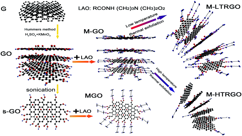 | ||
| Fig. 1 Schematic for the preparation of functional graphene. G: graphite; GO: graphite oxide; s-GO: single-layer graphene oxide; M-GO: alkylated graphite oxide; MGO: alkylated graphene oxide; (top) M-LTRGO: low-temperature thermal exfoliation alkylated graphite oxide; (bottom) M-HTRGO: high-temperature (1050 °C) exfoliation alkylated graphite oxide under an Ar atmosphere. | ||
Results and discussion
The structure and morphology of M-LTRGO was characterized via physical characterization, as shown in Fig. 2. Low-magnification TEM images (Fig. 2(A) and (B)) indicate that the samples are homogeneous micrometer-sized flakes with a low contrast, indicating a small thickness18 due to the high peeling effect. The crystal structure at the edge of the M-LTRGO sheets cannot be directly observed in the TEM images (Fig. 2(C) and (D)),42,43 which may be due to the fact that graphene sheets stacked and thickened after the low-temperature thermal reduction. A SAED pattern obtained from the same area is shown in Fig. 2(C) (top inset); an amorphous structure is indicated by the diffuse diffraction pattern,44 owing to the folded layers with different crystalline orientations18 after low-temperature thermal reduction. The number of layers could be measured from the folded regions and the AFM images (Fig. 2(G) and (H)); the thinnest sheet is only 0.36 nm and the thickest sheet is about 5 nm. The SEM images (Fig. 2(E) and (F)) intuitively indicate that the M-GO was fully and uniformly exfoliated into 3D-structured graphene via a low-temperature thermal treatment. On the other hand, the specific surface areas (SSA) based on the BET method (SBET) and total pore volumes (Vt) of LTRGO are 359.103 m2 g−1 and 1.120 cm3 g−1, respectively, and it shows type-IV adsorption isotherms45 as observed from the adsorption–desorption curve (in the ESI S3†); this further indicates the complete and uniform exfoliation of M-GO.17 The above mentioned results illustrate that the low-temperature expansion technology can realize a similar and efficient exfoliation effect as that realized via a high-temperature thermal exfoliation method.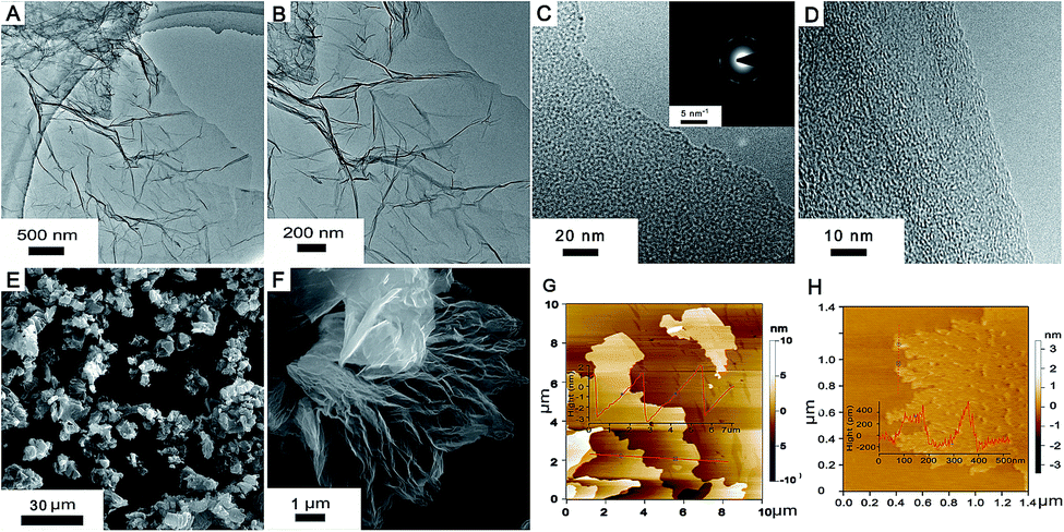 | ||
| Fig. 2 Structure and morphology of M-LTRGO. (A and B) Low-magnification TEM images of the M-LTRGO segment. (C and D) High-magnification TEM images (C-inset: SAED pattern at the same location, scale bar, 5 nm−1). (E and F) SEM images. (G and H) AFM images. | ||
The MGO and M-HTRGO were prepared to compare with M-LTRGO. They unilaterally have a better modification degree (the MGO has excellent lipophilicity and could disperse in xylene, butanol, and so on) and larger exfoliation degree. First, they displayed a significant difference in the morphology and structure, as shown in Fig. 3. The layers of M-LTRGO (Fig. 3(C)) and M-HTRGO (Fig. 3(D)) were exfoliated to a large extent, and both of them had stable 3D structures, which were further confirmed via the TEM characterizations (in the ESI S2†). In addition, the higher resolution images could be easily achieved without any pretreatment, suggesting the enhanced conductivity of M-LTRGO18 (in ESI S1,† the surface resistance for graphene pastes and detailed investigations are presented). However, the layers of MGO (Fig. 3(B)) were still tightly stacked and the electric beam was obviously aggregated similar to those of GO (Fig. 3(A)).
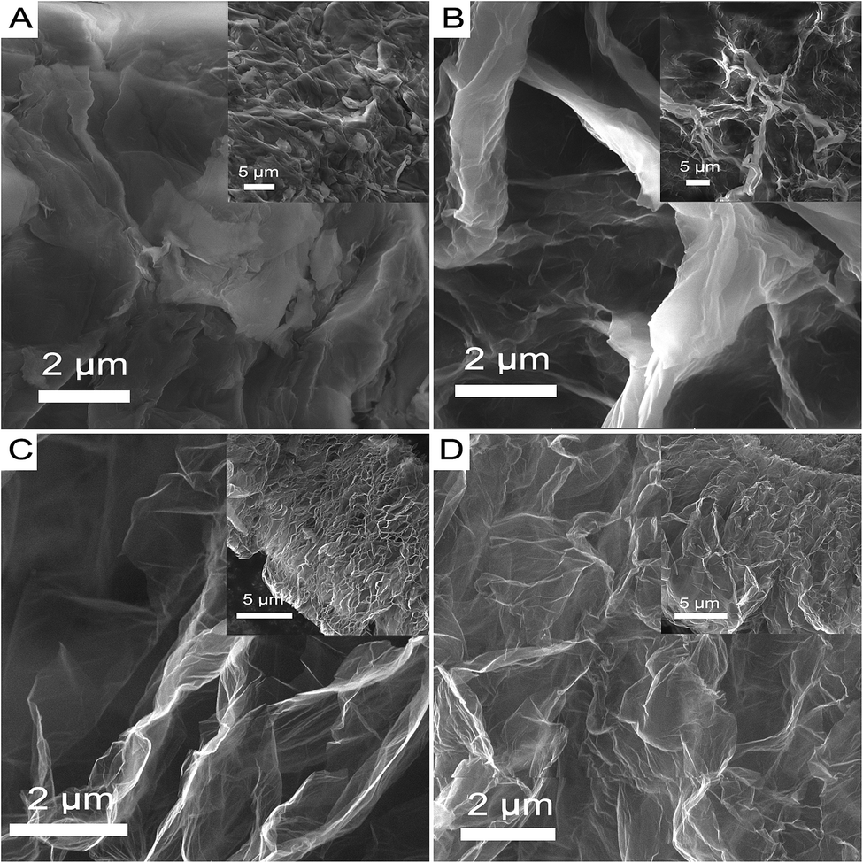 | ||
| Fig. 3 SEM images of GO (A), MGO (B), M-LTRGO (C), and M-HTRGO (D). | ||
The exfoliation degree and the modification effect of M-LTRGO and MGO were characterized via X-ray diffraction (XRD). Fig. 4 exhibits the XRD patterns of natural graphite, GO, M-GO, M-LTRGO, and M-HTRGO. The natural graphite was characterized by a sharp (002) peak at 26.5° with a typical interlayer spacing of 0.34 nm. The XRD pattern of graphite oxide shows a typical (002) peak located at 10.98°, corresponding to an interlayer spacing of 0.81 nm, which agrees well with previous results.46,47 After modification with LAO, the typical (002) peak of the MGO shifted to 6.38°, corresponding to an interlayer spacing of 1.38 nm; this certifies the effective modification of GO because of the increase in the (002) interlayer spacing. On the other hand, the intense diffraction peak proves the significant layer stacking of the MGO.48 After low-temperature expansion to M-GO, the sharp peak around 10.98° disappeared, indicating the removal of the oxygen-containing groups and the sufficient peeling18 of ordered stacked graphite oxide sheets during the low-temperature thermal treatment process. Based on the results of the XRD patterns, the ranking of the exfoliation degree should be M-HTRGO > M-LTRGO > MGO, which was further proved by the surface area analysis. The specific surface area (SSA) value of the above mentioned graphene is 476.16 m2 g−1, 359.10 m2 g−1, and 7.46 m2 g−1, respectively. The detailed data are shown in Table 1 of the ESI.†
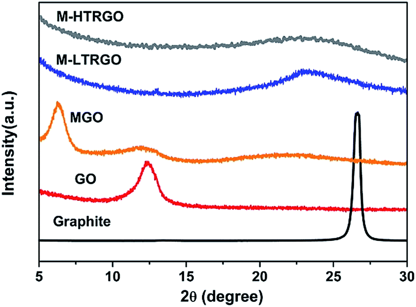 | ||
| Fig. 4 XRD patterns of GO, MGO, M-LTRGO, and M-HTRGO. | ||
The chemical structure and composition changes on the surface of GO were demonstrated mainly through the FTIR spectra and the XPS fitting spectra. Fig. 5 shows the FT-IR spectra of GO, MGO, M-LTRGO and M-HTRGO. The typical peaks appeared at 3437, 1632 and 1066 cm−1, corresponding to the presence of hydroxyl, carboxyl and epoxy groups, respectively.49 Compared with GO and MGO, the broad peak intensity at 3437 cm−1 (OH stretching vibration) in the spectrum of M-LTRGO and M-HTRGO significantly decreased, which indicated absence of hydrophilic functional groups.17 After thermal reduction, the asymmetric peaks at 2920 and 2845 cm−1 assigned to the CH2 stretching vibrations of the alkyl group obviously became weaker and even disappeared. However, the alkyl group peaks for M-LTRGO were still retained, which illustrated that the M-LTRGO could maintain enough alkylated chain as compared to M-HTRGO through different thermal expansion process.
 | ||
| Fig. 5 FT-IR spectrum of GO, MGO, M-LTRGO and M-HTRGO. | ||
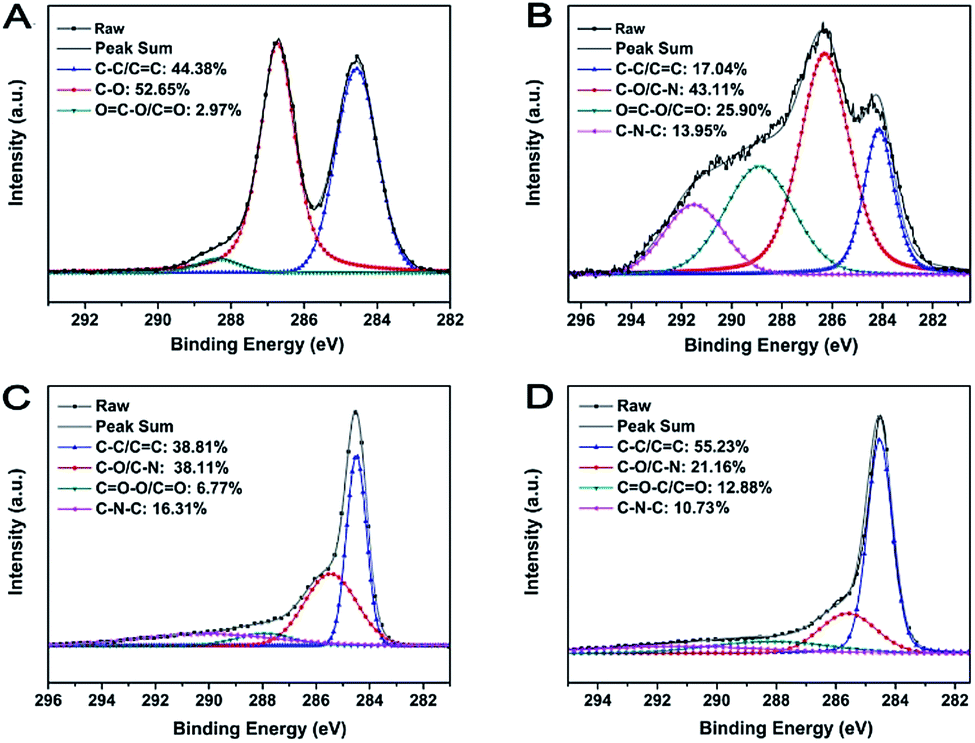
The surface chemistry composition and the reduction degree of M-LTRGO and the parallel graphene were further quantitatively characterized using X-ray photoelectron spectra (XPS). The spectrum shown in Fig. 6(B) displays the C 1s peaks of M-GO; the C–N bond (285.6 ± 0.3 eV) and the C–C–N bond (291.5 ± 0.3 eV) of the C 1s spectrum certifies the successful modification with LAO.50,51 After low temperature (170 °C) and high temperature (1050 °C) thermal treatment, the proportion of the fitting peak area (Fig. 6(C) and (D)) corresponding to the organic functional groups significantly reduced as compared to that of the MGO (Fig. 6(B)). The ratio of SC–C/C![[double bond, length as m-dash]](https://www.rsc.org/images/entities/char_e001.gif) C/Sall increased from 17.04% to 38.81% and 55.23%, which indicated the removal of a large quantity of organic groups during the low- and high-temperature thermal expansion processing.24 In addition, the ratio of SC–N–C/Sall and SC–N/C–O/Sall in the M-LTRGO XPS fitting spectrum is 16.31% and 38.11%, which is much higher than 10.71% and 21.76% for M-HTRGO. This suggests M-LTRGO retained more lipophilic groups than M-HTRGO during the thermal process, which is highly consistent with the result of the FT-IR analysis.
C/Sall increased from 17.04% to 38.81% and 55.23%, which indicated the removal of a large quantity of organic groups during the low- and high-temperature thermal expansion processing.24 In addition, the ratio of SC–N–C/Sall and SC–N/C–O/Sall in the M-LTRGO XPS fitting spectrum is 16.31% and 38.11%, which is much higher than 10.71% and 21.76% for M-HTRGO. This suggests M-LTRGO retained more lipophilic groups than M-HTRGO during the thermal process, which is highly consistent with the result of the FT-IR analysis.
 | ||
| Fig. 6 The XPS fitting spectrum of GO (A), MGO (B), M-LTRGO (C), and M-HTRGO (D). | ||
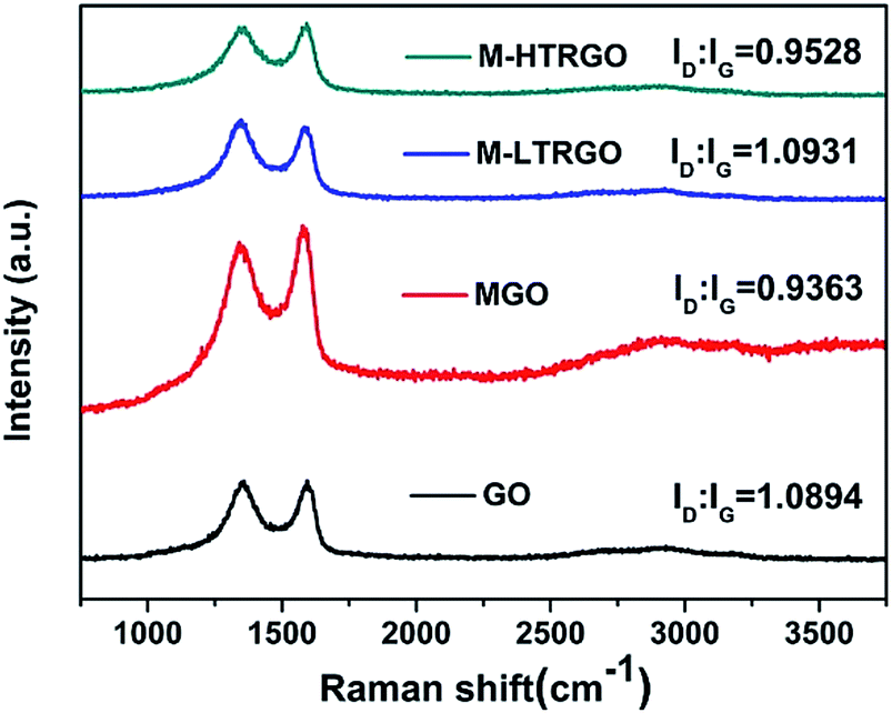
The structural changes of GO, MGO, M-LTRGO and M-HTRGO can be reflected via the variation of the relative intensities of G (the E2g mode of the sp2 carbon atoms) and D (the symmetry A1g mode) bands in the Raman spectrum. As depicted in Fig. 7, after modification and high temperature (1000 °C) reduction, the intensity ratio of the D/G bands decreased. This agrees well with the Raman spectrum of GO modified by dodecyl dimethyl benzyl ammonium chloride (1227)52 and thermally reduced GO.40 However, in the Raman spectrum of M-LTRGO, the intensity ratio of D/G clearly increased and the contribution of the increasing peak intensity originated from two factors: first, the morphology and structure of M-LTRGO transferred from a relative order (MGO) into disorder; second, the M-LTRGO was not subjected to the high-temperature annealing process.36
 | ||
| Fig. 7 Raman spectrum of GO, MGO, M-LTRGO, and M-HTRGO. | ||
As M-LTRGO was incorporated into polyolefin using a twin-screw mixer, Raman spectroscopy was preferred as a simple and effective method to analyse the interfacial interactions between the graphene sheets and polymer. Chen et al.53 suggested that the peak ratio (I2953,C–H2 stretching/I812,C–C,CO side chain stretching) of PMMA is related to the interaction between the PMMA molecular chains and the single wall carbon nanotubes (SWCNT), and the higher intensity of the backbone C–H2 stretching band suggests the stronger anisotropic interaction between PMMA and SWCNT in the melt-blended composites. Macosko et al.54 suggested that the peak ratio (I2935/I812) of TRG/i-PMMA and PG/i-PMMA increases with higher loadings and the i-PMMA molecules at the interface are aligned by graphene sheets, which is in agreement with the study reported by Chen et al.53 The molecular structure of PP and PE are similar to that of PMMA; the peaks (2882 cm−1, I2882) and (812 cm−1, I812) in the Raman spectrum are the C–H2 stretching and C–C side chain stretching vibration, respectively. The peak ratios (I2882/I812) for the pure polyolefin and the composites are shown in Fig. 8. The Raman peak ratios reported in this study are independent of the compatibility and dispersibility of the two components at the same loadings. The higher peak ratio (I2882/I812) of polyolefin/M-LTRGO (including PP, PPR, and LLDPE) suggests that the M-LTRGO has a stronger anisotropic interaction with the polyolefin matrix due to the balanced exfoliation degree and modification degree. The stronger anisotropic interaction between M-LTRGO and the polyolefin matrix eventually contributes to the enhancement in the mechanical property and thermal stability.
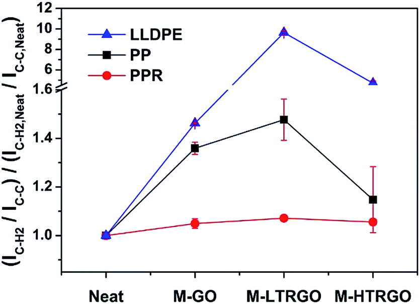 | ||
| Fig. 8 Raman peak ratio (I2882/I812) for double screw melting blending graphene/polyolefin nanocomposites. Error bars represent a range of readings obtained from five measurements at randomly selected locations. Spectrum are shown in the ESI S4.† | ||
The mechanical properties of graphene-based polyolefin nanocomposites were tested via the Instron testing system and are shown in Fig. 9. The M-LTRGO showed significantly improved enhancement in the tensile breaking strength, elongation at break and bending strength at a low loading of 0.5 wt% as compared to parallel graphene. In particular, the tensile breaking strength increased by 42.77% and 58.59% with the incorporation of PPR and LLDPE, respectively, which was a small breakthrough for graphene-based polyolefin composites prepared by a double screw melting blending. Note that the Charpy impact strength reduced in the three kinds of polyolefin nanocomposites. However, the M-LTRGO-based polyolefin nanocomposites maintained the most impact performance that even increased in the PP matrix. The key to this excellent performance for polyolefin/M-LTRGO is that M-LTRGO takes advantages of both M-GO and M-HTRGO, which results in a stronger anisotropic interaction with the polymer, supported by Raman characterization shown in Fig. 8. Because good modification is the basis of compatibility, the large SSA contributes more to the dispersibility of graphene in the matrix during the melting blending process. The M-LTRGO not only conveniently took the advantages of two types of graphene but also simultaneously avoided their shortcomings (difficult to disperse and low compatibility) during the melting blending process and eventually exhibited excellent performance in the graphene-based polyolefin nanocomposites.
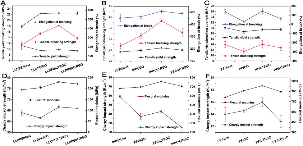 | ||
| Fig. 9 Mechanical characterizations for double screw melting blending of graphene/polyolefin nanocomposites. Error bars represent standard deviation for seven parallel measurements for each sample: tensile yield strength, tensile breaking strength, elongation at break, flexural modulus, and impact strength of a simply supported beam. Text detailed data are shown in the ESI Tables 2–4.† | ||
The UV transmission spectrum of graphene-based polyolefin composites are illustrated in Fig. 10. In particular, the curves of the neat polyolefin showed a high UV transmittance, especially in the longer-wavelength (340–400 nm) region. The UV transmission spectrum of graphene-based polyolefin composites showed a dramatic decline for different kinds of graphene, implying that the low content of graphene could effectively block UV rays.41 Note that M-LTRGO- and M-HTRGO-based polyolefin composites showed a more pronounced decline of UV transmission and higher UPF values than the M-GO-based polyolefin, which confirmed the better dispersibility of M-LTRGO and M-HTRGO than that of M-GO during the melting blending process because of the relatively large specific area. Although MGO had a more complete modification degree, polyolefin/MGO eventually could not show an improved enhancement in the mechanical properties and the Raman characteristic peak ratio because of the extremely low dispersibility in the matrix.
 | ||
| Fig. 10 The UV transmission spectrum of the graphene/polyolefin nanocomposites (A–C) and the UPF values of the sample sheets (D). The thickness of the polyolefin composites samples is uniformly 0.80 mm. | ||
The storage modulus represents the stiffness of a viscoelastic material and is proportional to the energy stored during a loading cycle. The tan![[thin space (1/6-em)]](https://www.rsc.org/images/entities/char_2009.gif) δ is a measure of the energy loss, which is defined as the ratio of the loss modulus to the storage modulus. The storage modulus of the graphene–polyolefin composites significantly increased when the M-LTRGO and other parallel graphene were mixed via melting blending with polyolefin, as shown in the ESI S5;† this could be attributed to the mechanical interlocking55 between graphene and the matrix due to the presence of alkylated short chain on the graphene surface. The thermal properties of the nanocomposites were tested using a Perkin Elmer Diamond thermal analyzer (Fig. 11). Obviously, the polyolefin/M-LTRGO composites displayed best thermal stability as compared to their counterparts; the thermal decomposition temperature of Td20 improved 35 °C, 33 °C and 21 °C for a PP-sp179, PPR, and LLDPE matrix, respectively. The reason that the polyolefin/M-LTRGO shows better thermal stability than the parallel composites is the huge interfacial area and the strong hydrophobic–hydrophobic interactions2,25,55 between polyolefin and the M-LTRGO nanocomposites obtained via the double screw melting blending technology, as mentioned in Fig. 8–10.
δ is a measure of the energy loss, which is defined as the ratio of the loss modulus to the storage modulus. The storage modulus of the graphene–polyolefin composites significantly increased when the M-LTRGO and other parallel graphene were mixed via melting blending with polyolefin, as shown in the ESI S5;† this could be attributed to the mechanical interlocking55 between graphene and the matrix due to the presence of alkylated short chain on the graphene surface. The thermal properties of the nanocomposites were tested using a Perkin Elmer Diamond thermal analyzer (Fig. 11). Obviously, the polyolefin/M-LTRGO composites displayed best thermal stability as compared to their counterparts; the thermal decomposition temperature of Td20 improved 35 °C, 33 °C and 21 °C for a PP-sp179, PPR, and LLDPE matrix, respectively. The reason that the polyolefin/M-LTRGO shows better thermal stability than the parallel composites is the huge interfacial area and the strong hydrophobic–hydrophobic interactions2,25,55 between polyolefin and the M-LTRGO nanocomposites obtained via the double screw melting blending technology, as mentioned in Fig. 8–10.
 | ||
| Fig. 11 TGA curves of graphene-based polyolefin composites. (A-LLDPE, B-PPR, and C-PP) TGA curves and (D-LLDPE, E-PPR, and F-PP) 1st derivative derived from the TGA curves of the polyolefin-based graphene composites. (Heating rate is 10 °C min−1). The detailed thermal stability data are shown in the ESI Table 5.† | ||
Conclusions
We developed a low temperature (170 °C), rapid thermal exfoliation technology for large-scale synthesis of high quality 3D morphology functional graphene from alkylated graphite oxide. This graphene has a higher reduction and exfoliation extent, along with a huge specific surface area and stable 3D morphology. In addition, it could maintain more functional groups because of a stable 3D open architecture. Its special architecture achieved an excellent balance between the interfacial compatibility and dispersibility of graphene to the polyolefin matrix. After incorporation in polyolefin (PP and LLDPE), the M-LTRGO based polyolefin composites showed excellent mechanical (nearly 42.77% and 58.59% increase in tensile breaking strength at a loading of 0.5 wt% in PPR and LLDPE, respectively) and thermal properties as compared to modified graphene oxide and high temperature thermally reduced graphene. This low-temperature preparation technology provides a new route for the industrial large-scale preparation of functional graphene, which is also expected to be applied in polymer composites and other fields such as energy, chemical industry, and building materials.Experimental
Preparation of M-GO, LTRGO, and M-LTRGO
GO was prepared using a modified Hummers method.37 Briefly, graphite flakes (25 g) were put into concentrated H2SO4 (500 mL) and kept in an ice bath (<5 °C). KMnO4 (150 g) was gradually added under stirring to keep the temperature of the mixture below 30 °C. After stirring for 24 h, the mixture was slowly diluted using 3 L distilled water. After this, 30% H2O2 solution (50 mL) was slowly added to the mixture in case if the mixture ejected from the container. Upon addition, the mixture turned bright yellow while bubbling. The mixture coagulated and was washed several times with 5–10% HCl solution for removing the remaining metal and sulfate ions, followed by repeated washings with distilled water until the pH of the solution became close to neutral. Eventually, the graphite oxide solution was freeze-dried at −35 °C and 6–8 Pa for 72 h.MGO (modified graphene oxide) was prepared in a beaker by adding an optimized amount of lauramidopropylamine oxide (LAO) to the designed graphene oxide solution.38 The resultant mixture was then ultrasonicated and stirred for 30 minutes at room temperature (25 °C). Eventually, the precipitates were washed via suction filtration and freeze-dried. The modified graphite oxide (M-GO) has a similar synthetic method except that the raw material is graphite oxide. After finishing the addition of LAO, graphite oxide rapidly flocculated and deposited. Eventually, the modified graphite oxide was filtered and dried to prepare it for the thermal reduction experiment.
M-LTRGO was produced from modified graphite oxide (M-GO) in a tube heating furnace via two steps, as shown in Fig. 1. Step 1: M-GO was kept for 5–10 minutes at 80 °C in a drying oven; step 2: M-GO was rapidly heated to 170 °C for one minute in a tube furnace; caution: slight explosion phenomenon occurred some seconds later; eventually, the expanded powder was obtained and further dried. The whole synthesis period is 15 min including the preparation time of about 12 min, and the thermal expansion is instantly finished.
M-HTRGO was produced from M-GO via ultra-rapid thermal treatment at 1050 °C (ref. 39 and 40) under an argon protection. The thermal expansion is still instantly finished under the high temperature thermal shock.
Preparation of MGO, M-LTRGO, and M-HTRGO-based polyolefin nanocomposites
PP/MGO, PP/M-LTRGO, and PP/M-HTRGO nanocomposites were prepared via melt blending using a Lab Tech, co-rotating twin-screw extruder having a L/D of 40 and a screw diameter of 25 mm. PP compounded with 0.5 wt% MGO, 0.5 wt% M-LTRGO, and 0.5 wt% M-HTRGO was denoted as PP/MGO, PP/M-LTRGO, and PP/M-HTRGO, respectively.Twin-screw extrusion granulation: 5 g MGO, 5 g M-LTRGO, and 5 g M-HTRGO were separately mixed with 1000 g PP-sp179 (purchased from Lanzhou Petrochemical Research Center. China). After mixing in a high-speed mixer (10 min), the premix was dried for 12 h at 80 °C in an oven and then added to a twin-screw extruder at a barrel temperature of 200-210-215-220-210 °C; eventually, the graphene/PP nanocomposite granules were obtained. The PPR/graphene and LLDPE/graphene nanocomposites were prepared by the same recipe, and the designed graphene species with the PP/graphene nanocomposites are shown in the ESI Table 6.† The standard text splines were prepared via injection molding (plasticizing temperature: 230 °C; inject pressure: 40 MPa; and mold temperature: 50 °C).
Characterization methods
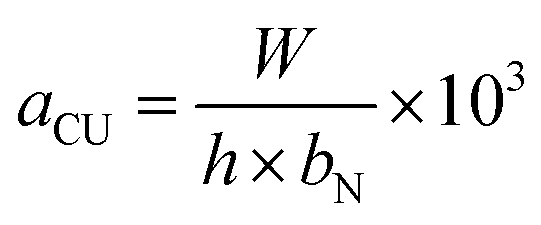
Elemental composition analysis was carried out using X-ray photoelectron spectroscopy (XPS, ESCALAB 250), in which a Shirley background was assumed. The microstructure of the samples was investigated by scanning electron microscopy (SEM-S4800), transmission electron microscopy (TEM-Hitachi H-600), and X-ray diffraction (XRD-Rigaku D/max-2400). Thermal gravimetric analysis (TGA) of the samples was performed using a Perkin-Elmer Diamond thermal analyzer from room temperature to 300 °C at a heating rate of 10°C min−1 with an Ar protection. The nature of the bonding was characterized by a Nicolet NEXUS 670 Fourier transform infrared spectroscope and Raman spectroscope (Horiba Jobin Yvon LABRAM-HR800 with a wavelength range of 0–4000 cm−1). The surface area and pore structure of the M-LTRGO was measured by N2 adsorption at 77 K using the BET method using a MICROMERITICS TriStarII 3020 surface analyzer.The tensile, bending property, and impact absorption energy were tested according to the China National Standard GB/T 1040.2-2006, GB/T 9341-2008, and GB/T 1043.1-2008, respectively. Notched specimens Charpy impact strength (kJ m−2) can be calculated by the following function:
The UV-blocking properties of the GO-LTRGO/PP nanocomposites (10 × 50 × 0.8 mm), as determined by the UV protection factor (UPF) and UV transmission spectra, were obtained by a UV spectrophotometer (UV1000F, Labsphere Inc., USA). On the basis of the obtained data, in accordance with the Australia/New Zealand standard AC/NZS 439:1996, UPF was calculated as follows:41

Acknowledgements
This work was supported by the Petro China Innovation Foundation (502000-071100003).Notes and references
- M. C. Hsiao, S. H. Liao, Y. F. Lin, C. A. Wang, N. W. Pu, H. M. Tsai and C. C. Ma, Nanoscale, 2011, 3, 1516–1522 RSC.
- C. Li, J. Vongsvivut, X. She, Y. Li, F. She and L. Kong, Phys. Chem. Chem. Phys., 2014, 16, 22145–22158 RSC.
- Y. Mo, M. Yang, Z. Lu and F. Huang, Composites, Part A, 2013, 54, 153–158 CrossRef CAS.
- X. Hu, E. Su, B. Zhu, J. Jia, P. Yao, Y. Bai, X. Hu, E. Su, B. Zhu and J. Jia, Compos. Sci. Technol., 2014, 97, 6–11 CrossRef CAS.
- S. Stankovich, D. A. Dikin, G. H. B. Dommett, K. M. Kohlhaas, E. J. Zimney, E. A. Stach, R. D. Piner, S. T. Nguyen and R. S. Ruoff, Nature, 2006, 442, 282–286 CrossRef CAS PubMed.
- X. Shen, Z. Wang, Y. Wu, X. Liu, Y. B. He and J. K. Kim, Nano Lett., 2016, 16(6), 3585 CrossRef CAS PubMed.
- H. Kim, Y. Miura and C. W. Macosko, Chem. Mater., 2010, 22, 3441–3450 CrossRef CAS.
- A. K. Geim and K. S. Novoselov, Nat. Mater., 2007, 6, 183–191 CrossRef CAS PubMed.
- T. Kuilla, S. Bhadra, D. Yao, N. H. Kim, S. Bose and J. H. Lee, Prog. Polym. Sci., 2010, 35, 1350–1375 CrossRef CAS.
- M. Kato, A. Usuki, N. Hasegawa, H. Okamoto and M. Kawasumi, Polym. J., 2011, 43, 583–593 CrossRef CAS.
- Y. Huang, Y. Qin, Y. Zhou, H. Niu, Z.-Z. Yu and J.-Y. Dong, Chem. Mater., 2010, 22, 4096–4102 CrossRef CAS.
- K. S. Novoselov, D. Jiang, F. Schedin, T. J. Booth, V. V. Khotkevich, S. V. Morozov and A. K. Geim, Proc. Natl. Acad. Sci. U. S. A., 2005, 102, 10451–10453 CrossRef CAS PubMed.
- K. R. Paton, E. Varrla, C. Backes, R. J. Smith, U. Khan, A. O'Neill, C. Boland, M. Lotya, O. M. Istrate and P. King, Nat. Mater., 2014, 13, 624–630 CrossRef CAS PubMed.
- Y. Zhang, L. Zhang, P. Kim, M. Ge, Z. Li and C. Zhou, Nano Lett., 2012, 12, 2810–2816 CrossRef CAS PubMed.
- K. H. Park, B. H. Kim, S. H. Song, J. Kwon, B. S. Kong, K. Kang and S. Jeon, Nano Lett., 2012, 12, 2871–2876 CrossRef CAS PubMed.
- K. Parvez, Z. S. Wu, R. Li, X. Liu, R. Graf, X. Feng and K. Mullen, J. Am. Chem. Soc., 2014, 136, 6083–6091 CrossRef CAS PubMed.
- M. J. McAllister, J.-L. Li, D. H. Adamson, H. C. Schniepp, A. A. Abdala, J. Liu, M. Herrera-Alonso, D. L. Milius, R. Car and R. K. Prud'homme, Chem. Mater., 2007, 19, 4396–4404 CrossRef CAS.
- W. Lv, D. M. Tang, Y. B. He, C. H. You, Z. Q. Shi, X. C. Chen, C. M. Chen, P. X. Hou, C. Liu and Q. H. Yang, ACS Nano, 2009, 3, 3730–3736 CrossRef CAS PubMed.
- G. Wang, J. Yang, J. Park, X. Gou, B. Wang, H. Liu and J. Yao, J. Phys. Chem. C, 2008, 112, 8192–8195 CAS.
- A. Ashori, S. Menbari and R. Bahrami, J. Ind. Eng. Chem., 2016, 38, 37–42 CrossRef CAS.
- Y. S. Yun, Y. H. Bae, D. H. Kim, J. Y. Lee, I. J. Chin and H. J. Jin, Carbon, 2011, 49, 3553–3559 CrossRef CAS.
- M. A. Rafiee, J. Rafiee, Z. Wang, H. Song, Z. Z. Yu and N. Koratkar, ACS Nano, 2009, 3, 3884–3890 CrossRef CAS PubMed.
- S. H. Ryu and A. M. Shanmugharaj, Chem. Eng. J., 2014, 244, 552–560 CrossRef CAS.
- X. Yang, T. Mei, J. Yang, C. Zhang, M. Lv and X. Wang, Appl. Surf. Sci., 2014, 305, 725–731 CrossRef CAS.
- M. Y. Song, S. Y. Cho, R. K. Na, S. H. Jung, J. K. Lee, Y. S. Yun and H. J. Jin, Carbon, 2016, 108, 274–282 CrossRef CAS.
- A. A. Vasileiou, M. Kontopoulou and A. Docoslis, ACS Appl. Mater. Interfaces, 2014, 6, 1916–1925 CAS.
- H. Kim, A. A. Abdala and C. W. Macosko, Macromolecules, 2010, 43, 6515–6530 CrossRef CAS.
- K. Das, S. Maiti, M. Ghosh, D. Mandal and P. K. Das, J. Colloid Interface Sci., 2013, 395, 111–118 CrossRef CAS PubMed.
- W. Meng, E. Gall, F. Ke, Z. Zeng, B. Kopchick, R. Timsina and X. Qiu, J. Phys. Chem. C, 2015, 119(36), 21135–21140 CAS.
- L. Suazon, D. Barry, J. Fletcher, K. Wisniewski and B. Thomas, US Pat., 6,440,925, 2002.
- M. T. García, E. Campos and I. Ribosa, Chemosphere, 2007, 69, 1574–1578 CrossRef PubMed.
- M.-C. Hsiao, S.-H. Liao, Y.-F. Lin, C.-A. Wang, N.-W. Pu, H.-M. Tsai and C.-C. M. Ma, Nanoscale, 2011, 3, 1516–1522 RSC.
- S. Choudhary, H. P. Mungse and O. P. Khatri, J. Mater. Chem., 2012, 22, 21032–21039 RSC.
- H. C. Schniepp, J. L. Li, M. J. Mcallister, H. Sai, M. Herrera-Alonso, D. H. Adamson, R. K. Prud'Homme, R. Car, D. A. Saville and I. A. Aksay, J. Phys. Chem. B, 2006, 110, 8535 CrossRef CAS PubMed.
- H. Bi, K. Yin, X. Xie, Y. Zhou, N. Wan, F. Xu, F. Banhart, L. Sun and R. S. Ruoff, Adv. Mater., 2012, 24, 5124–5129 CrossRef CAS PubMed.
- S. J. Yang, T. Kim, H. Jung and R. P. Chong, Carbon, 2013, 53, 73–80 CrossRef CAS.
- Y. Si and E. T. Samulski, Nano Lett., 2008, 8, 1679–1682 CrossRef CAS PubMed.
- N.-W. Pu, C.-A. Wang, Y.-M. Liu, Y. Sung, D.-S. Wang and M.-D. Ger, J. Taiwan Inst. Chem. Eng., 2012, 43, 140–146 CrossRef CAS.
- Z. S. Wu, W. Ren, L. Gao, J. Zhao, Z. Chen, B. Liu, D. Tang, B. Yu, C. Jiang and H. M. Cheng, ACS Nano, 2009, 3, 411–417 CrossRef CAS PubMed.
- Y. Fang, B. Luo, Y. Jia, X. Li, B. Wang, Q. Song, F. Kang and L. Zhi, Adv. Mater., 2012, 24, 6348–6355 CrossRef CAS PubMed.
- X. Hu, M. Tian, L. Qu, S. Zhu and G. Han, Carbon, 2015, 95, 625–633 CrossRef CAS.
- H. Zhang, J. Geng, R. T. Ott, M. F. Besser and M. J. Kramer, Metall. Mater. Trans. A, 2015, 46, 4078–4085 CrossRef CAS.
- H. Zhang, W. Ding, H. Kai and L. Ming, Nanoscale Res. Lett., 2010, 5, 1264 CrossRef CAS PubMed.
- D. C. Marcano, D. V. Kosynkin, J. M. Berlin, A. Sinitskii, Z. Sun, A. Slesarev, L. B. Alemany, W. Lu and J. M. Tour, ACS Nano, 2010, 4, 4806–4814 CrossRef CAS PubMed.
- M. D. Donohue and G. L. Aranovich, Adv. Colloid Interface Sci., 1998, 76–77, 137–152 CrossRef CAS.
- A. Nepal, G. Chiu, J. Xie, G. P. Singh, N. Ploscariu, S. Klankowski, T. Sung, J. Li, B. N. Flanders, K. L. Hohn and C. M. Sorensen, Appl. Phys. A: Mater. Sci. Process., 2015, 120, 543–549 CrossRef CAS.
- J. T. Choi, D. H. Kim, K. S. Ryu, H.-i. Lee, H. M. Jeong, C. M. Shin, J. H. Kim and B. K. Kim, Macromol. Res., 2011, 19, 809–814 CrossRef CAS.
- Z. Wu, H. Zhong, X. Yuan, H. Wang, L. Wang, X. Chen, G. Zeng and Y. Wu, Water Res., 2014, 67, 330–344 CrossRef CAS PubMed.
- D. Voiry, J. Yang, J. Kupferberg, R. Fullon, C. Lee, H. Y. Jeong, H. S. Shin and M. Chhowalla, Science, 2016, 353, 1413–1416 CrossRef CAS PubMed.
- J. Russat, Surf. Interface Anal., 1988, 11, 414–420 CrossRef CAS.
- B. Yuan, C. Bao, L. Song, N. Hong, K. M. Liew and Y. Hu, Chem. Eng. J., 2014, 237, 411–420 CrossRef CAS.
- Y. C. Hui and Z. Q. Chen, Chin. J. Inorg. Chem., 2013, 29, 922–928 CAS.
- B. Chen, M. Cinke, J. Li, M. Meyyappan, Z. Chi, J. P. Harmon, P. A. O'RourkeMuisener, L. Clayton and J. D'Angelo, Adv. Funct. Mater., 2005, 15, 1183–1187 CrossRef CAS.
- K. H. Liao, S. Aoyama, A. A. Abdala and C. Macosko, Macromolecules, 2014, 47, 8311–8319 CrossRef CAS.
- N. Song, J. Yang, P. Ding, S. Tang, Y. Liu and L. Shi, Ind. Eng. Chem. Res., 2014, 53, 19951–19960 CrossRef CAS.
Footnote |
| † Electronic supplementary information (ESI) available. See DOI: 10.1039/c7ra04139j |
| This journal is © The Royal Society of Chemistry 2017 |