
 Open Access Article
 This Open Access Article is licensed under a Creative Commons Attribution-Non Commercial 3.0 Unported Licence
Co9S8 activated N/S co-doped carbon tubes in situ grown on carbon nanofibers for efficient oxygen reduction†
Fang Wangae,
Ting Liu*a,
Yaofang Guoa,
Wenzhen Lib,
Ji Qic,
David Rooneyd and
Kening Sun *a
*a
aBeijing Key Laboratory for Chemical Power Source and Green Catalysis, School of Chemical Engineering and Environment, Beijing Institute of Technology, Beijing, 100081, China. E-mail: bitkeningsun@163.com; liuting@bit.edu.cn
bChemical and Biological Engineering Department, Iowa State University, Ames, IA50011, USA
cSchool of Chemical Engineering, Dalian University of Technology, Dalian, 116024, China
dSchool of Chemistry and Chemical Engineering, Queen's University Belfast, Belfast BT9 5AG, UK
eChemistry and Chemical Engineering Department, College of Life, Tarim University, Alar, 843300, China
First published on 11th July 2017
Abstract
Herein, we report a facile and environment-friendly route for the preparation of Co9S8 activated N/S co-doped carbon tubes (denoted as Co9S8@N/S–CT) in situ grown on a carbon nanofiber network derived from bacterial cellulose. The as-prepared Co9S8@N/S–CT has a novel microstructure with homogeneous and lotus root-like carbon tubes plugged with Co9S8 active substance, which are embedded in the carbon nanofibers. This nonprecious Co9S8@N/S–CT composite has a comparable catalytic activity for the oxygen reduction reaction and superior stability compared with commercial Pt/C catalyst. This is attributed to a synergistic catalytic effect due the intimate contact between Co9S8 active sites and the highly conductive heteroatom doped carbon tubes, showing the great potential for using the Co9S8@N/S–CT composite as a novel non-precious cathode catalyst in fuel cells or metal–air battery applications.
1 Introduction
In order to solve the problem of energy shortage and environmental pollution, people are committed to the exploitation of high efficiency, low cost and eco-friendly alternative energy transfer and storage systems.1–5 Electrocatalysts are vital to the field of renewable energy technologies such as rechargeable metal–air batteries and fuel cells.6,7 As such the employment of highly active and durable electrocatalysts to accelerate the oxygen reduction reaction (ORR) has practical significance to commercial fuel cell and rechargeable metal–air battery applications. In general, the ORR rate is relatively slow and hence Pt and its alloys have been used to overcome the sluggish kinetics and accelerate the overall conversion process.8–10However, the high cost of these noble metal catalysts limits their supply and the weak durability severely hinders their applicability to practical advancement. Thus, the development of low-cost ORR electrocatalysts which have high activity and improved durability is of paramount importance. Recently, non-precious metal embedded in the carbon matrix composites with nanostructure have arisen as a promising alternative ORR catalyst to platinum-based catalysts.11–13 In these catalysts, the interaction between metal materials and carbon matrix can effectively reduce the local oxygen adsorption on the surface of the carbon by promoting the electron transfer between the metal and carbon.14 Carbon matrix, in turn, can prevent the reunion and loss of metal components in the process of reaction. Therefore, this type of catalyst, even compared with platinum-based catalysts, shows relatively higher catalytic activity towards ORR.
Lately, a new, low-cost carbon material, three-dimensional (3D) carbon nanofibers (CNFs) have been prepared by adopting natural precursor bacterial cellulose (BC) hydrogel.15,16 Bacterial cellulose, as a kind of abundant and green biomass nanomaterial, has a large number of hydroxyl groups which can be used as the nucleation center for metal oxide or metal sulfide nanoparticles.17–19 More importantly, BC-derived CNFs have good electrical conductivity, which can be utilized to prepare a variety of flexible catalysts based on the BC-derived CNFs. Inspired by their excellent properties, we have reported a series of catalysts embedded in CNFs derived from BC, which demonstrated superior electrocatalytic activity and stability under alkaline media. These materials were comparable to commercial Pt/C and outperformed commercial IrO2 as well as RuO2.20,21
Meanwhile, nano-sized transition metal sulfides have been studied extensively of their prospective application in the energy conversion and storage devices because of their high catalytic potential in the field of electrocatalysis.22,23 Among a variety of transition metal sulfides, cobalt sulfides show a relatively good electrical conductivity, persistent high thermal stability and high theoretical energy.24 In order to improve their performance, there has been a tendency to develop cobalt sulfides and carbon nano-composite materials. Nanometer cobalt sulfide (Co9S8), which is metal-rich within the family of cobalt sulfides, has attracted more and more attention because it exhibits outstanding performance in many application fields covering supercapacitors,25 hydrodesulfurization,26 lithium ion batteries,27 dye sensitized solar cells,28 and electrocatalysts towards hydrogen evolution reaction (HER).29 For these applications, the nanostructures of the materials are particularly important because they can usually reduce the limitation of charge transfer, shorten the length of the diffusion layer which the active electrochemical ions go through, and also increase the surface active sites exposed to the electrolyte. As a result, researchers have been trying to develop liquid phase synthesis methods for preparation of Co9S8 nanostructures, such as nanoparticles, nanosheets, hollow nanospheres and nano-yolk–shell structures, as well as some composite structures combined with carbon nanomaterials.30–35 However, to the best of our knowledge, the synthesis of embedding Co9S8 into N/S co-doped carbon nanostructural framework derived from BC and its performance as ORR catalyst has not been studied yet.
In this work, we explored the effect of heating rate on the in situ synthesis of composite materials derived from BC, while a novel material, Co9S8@N/S–CT, was synthesized by controlling the heating procedure. This is a facile and green route for the preparation of Co9S8 nanocrystals activated N/S co-doped carbon tubes in situ grown on CNFs derived from bacterial cellulose. The process was implemented with a simple impregnation followed by pyrolysis. Co9S8 serves as active sites and carbon fibers are the source of carbon for in situ growth of lotus root-like carbon tubes, at the same time nitrogen and sulfur are co-doped into the carbon tubes. This study demonstrated that the promising Co9S8@N/S–CT has superior performance and stability as an efficient electrocatalyst towards ORR in the alkaline media.
2 Experimental
2.1 Materials and methods
Bacterial cellulose hydrogels were kindly provided by Ms CY Zhong (Hainan Yeguo Foods Co., Ltd., China). The wet BC pellicles were first cut into rectangular slices (4 × 5 cm2) and soaked in deionized water for 24 hours to remove acid. Afterwards, they were placed into liquid nitrogen to ensure a quick freeze followed by freeze drying for 48 hours. The resulting BC aerogels were then soaked in the solution consisting of CoCl2, thiourea and urea (mole ratio = 1![[thin space (1/6-em)]](https://www.rsc.org/images/entities/char_2009.gif) :2:100) and freeze-dried for another 48 hours. This processing method can preserve the tenuous network owing to the low surface tension. Finally, the resulting aerogels were annealed in a tubular furnace under a N2 atmosphere to complete the carbonization and doping thus the black and ultralight CNF-based aerogels were obtained. It is well understood that temperature will directly govern the pyrolysis products. In order to obtain well-structured Co9S8@N/S–CT, a moderate heating program was followed which is referred to the thermal gravimetric curves of BC (Fig. S1†). Specifically, it was firstly heated to 200 °C (2 °C min−1) and then up to 220 °C (1 °C min−1) with a dwelling time of 1 hour at 220 °C. The subsequent heating was up to 350 °C (1 °C min−1) with a dwelling time of 1 hour at 350 °C and the material was finally heated up to 900 °C within 180 min. For comparison, N/S–CNF samples were prepared using the same procedure without adding of CoCl2.
:2:100) and freeze-dried for another 48 hours. This processing method can preserve the tenuous network owing to the low surface tension. Finally, the resulting aerogels were annealed in a tubular furnace under a N2 atmosphere to complete the carbonization and doping thus the black and ultralight CNF-based aerogels were obtained. It is well understood that temperature will directly govern the pyrolysis products. In order to obtain well-structured Co9S8@N/S–CT, a moderate heating program was followed which is referred to the thermal gravimetric curves of BC (Fig. S1†). Specifically, it was firstly heated to 200 °C (2 °C min−1) and then up to 220 °C (1 °C min−1) with a dwelling time of 1 hour at 220 °C. The subsequent heating was up to 350 °C (1 °C min−1) with a dwelling time of 1 hour at 350 °C and the material was finally heated up to 900 °C within 180 min. For comparison, N/S–CNF samples were prepared using the same procedure without adding of CoCl2.
2.2 Characterization
The morphology of the as-prepared catalyst was observed by scanning electron microscopy (SEM, QUANTA FEG 250) and transmission electron microscopy (TEM, JEOL 2100F) inductively coupled high resolution transmission electron microscopy (HRTEM). Energy Dispersive Spectrometer (EDS) tests were carried out with a light element detector via the ZAF technique. X-ray diffraction (XRD) patterns were collected by a Rigaku Ultima IV diffractometer using Cu Kα radiation (λ = 1.5406 Å) with a filament current of 40 mA and a tube voltage of 40 kV. X-ray photoelectron spectroscopy (XPS) was conducted on Physical Electronics 5400 ESCA. Raman spectroscopy was performed on a Renishaw Micro-Raman spectroscopy system with an excitation wavelength of 532 nm. N2 adsorption/desorption measurements (BET, Quadrasorb SI, Quantachrome Instrument Corporation) were used to identify the specific surface area.2.3 Electrochemical measurements
The electrocatalytic activity was tested in a water jacketed integrated glass cell connected with a typical three-electrode system at room temperature. Glassy carbon (GC) was used as the working electrode, while Pt wire and Hg/HgO were used as counter electrode and reference electrode respectively. The testing system was equipped with a CHI 760 electrochemistry workstation (Shanghai Chenhua Instruments, Inc.) along with a rotating disk device (MSR, Pine Instruments, Inc.). An ethanol solution with a concentration of 2 mg catalyst per mL was prepared as the catalyst ink. Especially, Nafion solution (5%, 15 μl) was added to the ink in order to prevent the catalyst detaching from the electrode surface. After 10 min ultrasonic dispersion, the prepared catalyst ink (10 μl) was dripped onto a pre-polished GC electrode (5 mm diameter). The total catalyst loading was 0.08 mg cm−2. O2-saturated 0.1 M KOH aqueous solution served as the supporting electrolyte for the test of cyclic voltammetry (CV, the scan rate of 50 mV s−1), linear scanning voltammetry (LSV, the scan rate of 5 mV s−1) and chronoamperometry (the applied voltage of 0.4 V vs. RHE). As a control, CV tests were also carried out under N2 saturation to eliminate capacitance contributions. RDE measurements were scanned cathodically with rotation rates varying from 400 to 2500 rpm and with the scan rate of 5 mV s−1 in O2-saturated 0.1 M KOH aqueous solution. The transferred electron number (n) in ORR were determined by Koutecky–Levich (K–L) equation.36
| B = 0.2nFCoD2/3ov−1/6 |
3 Results and discussion
A facile strategy for the synthesis of metal-rich sulfide, Co9S8 enriched carbon tube in situ grown on N/S co-doped CNF networks derived from bacterial cellulose was illustrated in Fig. 1. Unlike other pyrolysis routes for preparing Co9S8 crystals, there were no hazardous surfactants or intricate procedures involved in the system and Co9S8@N/S–CT was generated via simple immersion followed by direct pyrolysis. In this case, the as-prepared Co9S8@N/S–CT composite was found to have a novel microstructure and exhibits competitive performance as an electrocatalyst for ORR.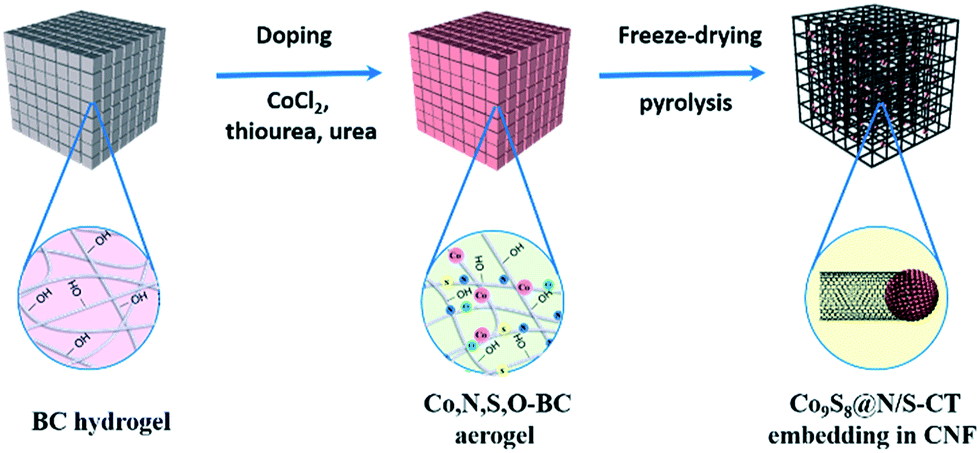 | ||
| Fig. 1 Illustration of the formation process of Co9S8@N/S–CT embedding in CNF. | ||
XRD characterization was conducted to determine the composition of the as-prepared materials. XRD pattern of the Co9S8@N/S–CT composite (Fig. 2a) indicates five characteristic peaks at 29.9°, 47.4°, 52.0°, 73.3° and 76.7°, respectively, which are indexed well to the cubic Co9S8 (JCPDS# 19-0364). It is clearly demonstrated that Co9S8 nanocrystals embedded in the hybrid composite. The diffraction peaks at 44.2°, 51.5° and 75.8° belong to three characteristics peaks of Co (111), Co (200) and Co (220) (JCPDS# 15-0806), and thus the Co-doping in the N/S–CNF is thereby proved. The strong peak at 26.0° from the graphite-like (002) structure suggests the existence of highly graphitic carbon. Studies have shown that, during the electrocatalytic process, high degree graphitization of carbon matrix can improve its electroconductibility and corrosion resistance of the carbon-based catalysts.6
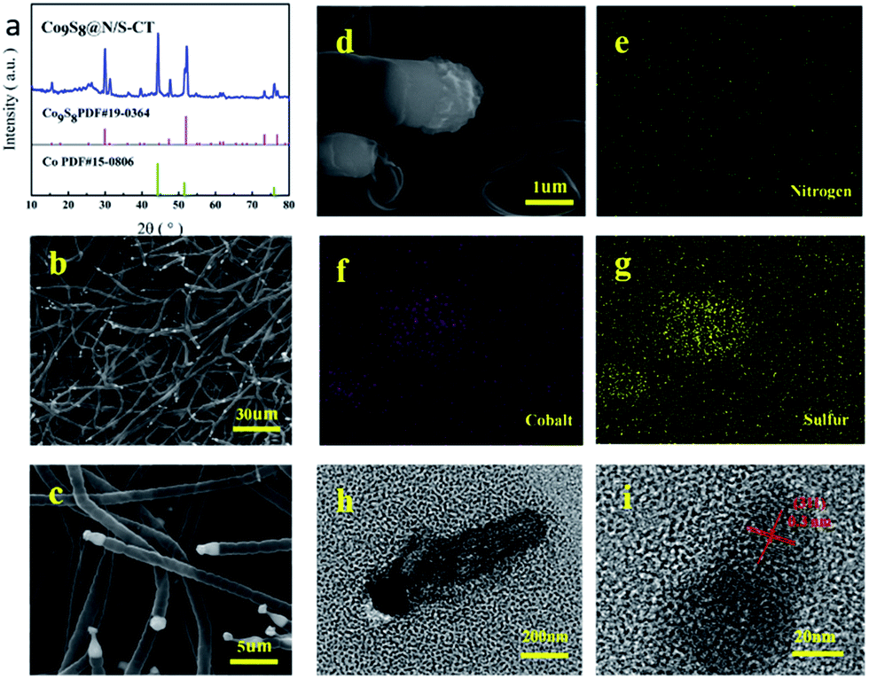 | ||
| Fig. 2 XRD patterns of Co9S8@N/S–CT sample (a); SEM images of Co9S8@N/S–CT at the magnifications of 30 μm (b) and 5 μm(c); SEM image of selected area of Co9S8CT@N/S–CT (d) on which element mapping was carried out and elemental mappings for nitrogen (e), cobalt (f) and sulfur (g); TEM image of Co9S8CT (h) and crystal fringes of the Co9S8CT (i). | ||
The EDS spectrum for determining element contents of the Co9S8@N/S–CT sample (Fig. S2†) shows that the composite material is comprised with C, N, S, Co and O elements. Different magnification SEM images of Co9S8@N/S–CT composite (Fig. 2b–d) depicted that the nanofibers maintain the porous, interconnected and well-defined 3D structure of BC aerogels. It surprised us that, on the outer surface of the CNFs, there are a large number of carbon tubes in situ grown on the surface of the CNF layers. The shape of the carbon tubes is not as same as the normal carbon tubes, but similar to the lotus root, and one end of the hollow tubes are plugged with the Co9S8, which looks like corks plugged into the bottles. From the high-magnification SEM images we can read that the average diameter of the carbon tubes is ca. 1 μm. It is noted that embedding the metal and metal sulfide nanoparticles into the CNFs have a great impact on the structure of the as-prepared material (Fig. S3a†).
The elemental mapping images of the Co9S8@N/S–CT composite are shown in Fig. 2e–g. It can be seen clearly that the Co and S elements are mainly distributed in the position of the end tip of carbon tubes. Combined with the results of XRD patterns it can be inferred that the composition of the plugged substance at the end of the carbon tubes could be Co9S8 nanocrystals (Fig. S3b†). The other elements including C, N and O are distributed uniformly on the carbon tubes and the main component of the carbon tubes is C element. Moreover, the surface of the carbon tubes was determined to be co-doped with N and S elements, which is due to the addition of urea and thiourea. Furthermore, a low quantity of cobalt metal was found to be embedded in carbon tubes or nanofibers surface in the form of nanoparticles. From the above comprehensive information, it can be concluded that the as-prepared composite material composed of N/S co-doped carbon tubes plugged with Co9S8 nanocrystal as active substance, which was supported by CNF framework.
TEM observation was conducted to further determine the composition of Co9S8 plugged carbon tube (denoted as Co9S8CT). As shown in Fig. 2h and i, it can be seen a clear carbon tube, the end part of which shows in deep black. The further analysis found that crystal lattice spacing was observed under 20 nm, which confirms the composition of this material. As shown in Fig. 2h and i, it can be observed obvious lattice characteristics in the part of deep black tip of the carbon tubes. The observed lattice fringe is approximately 0.3 nm, corresponding to the (311) plane of cubic phase of Co9S8. No obvious lattice characteristics were observed in the part of the carbon tubes, which indicates that the carbon tubes are composed of amorphous carbon. This result is expected as impurity atoms doped into the architecture of carbon will increase the disorder of carbon, making it loose its crystal structure.
Based on the characterization results, we come up with a possible growth mechanism of Co9S8 activated carbon tubes through an embedding process into the N/S doped CNF network. Under the given polymerization, carbon tubes were in situ grown out and the carbon derived from the CNF matrix. At first, Co2+ was reduced to the corresponding Co crystal by thiourea. With the enrichment of Co crystals especially those on the tip of carbon tubes,37 the generated S further reacts with Co and forms Co9S8 crystals which will enrich in the direction of carbon tubes and result in Co9S8 activated carbon tubes. This also explains why the Co9S8 activated carbon tube only arises at the tip of the carbon tubes. Urea is regarded as a precursor for the N-doping and thiourea serves as the source of sulfur (S) for the S-doped carbon substrate. Oxygen is sent out by O2 and/or CO2 gas. As it is pyrolysed, thiourea generates polymeric carbon nitride through a polyaddition/condensation process. It is certain that the carbon nitride gaseous fragment (e.g., C2N2+, C3N2+, C3N3+) is decomposed over 700 °C which offers both the C and N to generate N-doped carbon matrix.38,39 At the same time, Co2+ ions get reduced to form Co9S8 with S. Noted that here some of Co does not form sulfides but dopes into CNF as well as N and S. In this context, it may be supposed that the presence of C–N catalyzes the sulfide formation.40
The morphological characteristics of the as-prepared materials were further examined by Raman spectroscopy. The Raman spectrum of Co9S8@N/S–CT sample exhibits two characteristic peaks at 1342 cm−1 and 1587 cm−1, corresponding to the well-defined D-band and G-band (Fig. S4†). ID/IG ratio, which is used to value the extent of defects and the degree of graphitization in the catalysts, of the Co9S8@N/S–CT and CNF are estimated to be 1.33 and 1.15, respectively. It is suggested that the existence of transition metal or transition metal sulfides endows Co9S8@N/S–CT more defects and simultaneously improves the graphitization degree of carbon material which is in favor of electrical conductivity.41 Meanwhile, the specific surface areas of the catalysts were determined via N2 adsorption–desorption isotherms based on the Brunauer–Emmett–Teller (BET) method. As shown in Fig. S5,† Co9S8@N/S–CT complies a type-III isotherm with the specific surface area of 362.7 m2 g−1. In comparison with Co9S8@N/S–CT, CNF has a much lower specific surface area of 129.5 m2 g−1. It can be further deduced that the introduction of the transition metal or transition metal sulfides provides more defects and thus increases the specific surface area of the resulting material. And then the high specific surface area of Co9S8@N/S–CT composite could offer more active sites for oxygen molecules, resulting in enhanced ORR catalytic performance. Besides, the 3D nanostructure offers more opportunities for efficient mass transport which could also enhance the electrochemical activity.42
X-ray photoelectron spectroscopy (XPS) for Co9S8@N/S–CT composite was conducted with the full range spectra to probe the electronic states and determine the proportions of the surface species in catalyst materials, as displayed in Fig. 3. Five peaks were observed in the detailed C 1s spectrum which can be ascribed to C![[double bond, length as m-dash]](https://www.rsc.org/images/entities/char_e001.gif) C (284.6 eV), C–S (284.1 eV), C–N (285.2 eV), C–O (286.0 eV) and CO (288.2 eV) (Fig. 3a). It illustrates that nitrogen and sulfur are co-doped into the carbon matrix which is assumed to promote the oxygen reduction.43 The N-doping in the carbon matrix (12.3 at%) originates from the urea precursor. Whereas the S-doping in carbon matrix (10.9 at%) comes from thiourea, apart from forming Co9S8 embedded in N-doped carbon, implying the strong coupling between the Co9S8 and the N/S co-doped carbon matrix. The existence of C–O illustrates that the Co9S8@N/S–CT maintained the nanostructure of CNF, on which there are a quantity of oxygen-containing functional groups. Two main peaks detected at 779.9 and 794.9 eV in Co 2p detailed spectra (Fig. 3b) are the binding energies of Co 2p3/2 and Co 2p1/2, respectively. The energy separation between Co 2p3/2 and Co 2p1/2 of 15.0 eV is found to be accordance with the Co 2p of Co9S8.44,45 It also involves satellite peaks of Co 2p3/2 and 2p1/2 locating at 782.9 and 797.9 eV, accordingly. Therefore, it can be confirmed that cobalt sulfide is in the form of Co9S8 in the as-prepared Co9S8@N/S–CT composite combined with the above analysis. A small peak at 786.5 eV corresponds to Co metal which is in agreement with the XRD results. However, the content of Co metal is only 4.68% of the total Co implying that the most Co is in the form of Co9S8. Moreover, Fig. 3c shows a high-resolution XPS scan of the N 1s signal, which was deconvoluted into two major peaks located at 399.9 and 397.3 eV corresponding to pyrrolic N and pyridinic N, two minor peaks at 405.6 and 402.1 eV corresponding to chemisorbed and quaternary N, and a small peak at 404.2 eV corresponding to pyridinic N-oxide. Previous studies showed that N-doping in the carbon matrix could improve the electronic transmission rate and chemical reactivity.46 Noticeably, 48.5% of total nitrogen in the Co9S8@N/S–CT composite is the pyridinic N, which has been known to have a positive impact on ORR onset potential. The rest forms of nitrogen are favorable to the electrochemical properties of carbon matrix by enhancing the initial chemical adsorption of oxygen.47 Furthermore, Fig. 3d provides the detailed S 2p XPS spectra showing the binding energy of Co9S8. It contains two distinct peaks at 163.3 eV and 164.2 eV which can be assigned to the doublet S 2p3/2 and S 2p1/2 binding energies, respectively. Two peaks of 167.3 eV and 170.5 eV are attributed to carbon bonded S–Ox, which indicates that sulfur (S) originated from thiourea reductant, were oxidized to sulfite and sulfate.
C (284.6 eV), C–S (284.1 eV), C–N (285.2 eV), C–O (286.0 eV) and CO (288.2 eV) (Fig. 3a). It illustrates that nitrogen and sulfur are co-doped into the carbon matrix which is assumed to promote the oxygen reduction.43 The N-doping in the carbon matrix (12.3 at%) originates from the urea precursor. Whereas the S-doping in carbon matrix (10.9 at%) comes from thiourea, apart from forming Co9S8 embedded in N-doped carbon, implying the strong coupling between the Co9S8 and the N/S co-doped carbon matrix. The existence of C–O illustrates that the Co9S8@N/S–CT maintained the nanostructure of CNF, on which there are a quantity of oxygen-containing functional groups. Two main peaks detected at 779.9 and 794.9 eV in Co 2p detailed spectra (Fig. 3b) are the binding energies of Co 2p3/2 and Co 2p1/2, respectively. The energy separation between Co 2p3/2 and Co 2p1/2 of 15.0 eV is found to be accordance with the Co 2p of Co9S8.44,45 It also involves satellite peaks of Co 2p3/2 and 2p1/2 locating at 782.9 and 797.9 eV, accordingly. Therefore, it can be confirmed that cobalt sulfide is in the form of Co9S8 in the as-prepared Co9S8@N/S–CT composite combined with the above analysis. A small peak at 786.5 eV corresponds to Co metal which is in agreement with the XRD results. However, the content of Co metal is only 4.68% of the total Co implying that the most Co is in the form of Co9S8. Moreover, Fig. 3c shows a high-resolution XPS scan of the N 1s signal, which was deconvoluted into two major peaks located at 399.9 and 397.3 eV corresponding to pyrrolic N and pyridinic N, two minor peaks at 405.6 and 402.1 eV corresponding to chemisorbed and quaternary N, and a small peak at 404.2 eV corresponding to pyridinic N-oxide. Previous studies showed that N-doping in the carbon matrix could improve the electronic transmission rate and chemical reactivity.46 Noticeably, 48.5% of total nitrogen in the Co9S8@N/S–CT composite is the pyridinic N, which has been known to have a positive impact on ORR onset potential. The rest forms of nitrogen are favorable to the electrochemical properties of carbon matrix by enhancing the initial chemical adsorption of oxygen.47 Furthermore, Fig. 3d provides the detailed S 2p XPS spectra showing the binding energy of Co9S8. It contains two distinct peaks at 163.3 eV and 164.2 eV which can be assigned to the doublet S 2p3/2 and S 2p1/2 binding energies, respectively. Two peaks of 167.3 eV and 170.5 eV are attributed to carbon bonded S–Ox, which indicates that sulfur (S) originated from thiourea reductant, were oxidized to sulfite and sulfate.
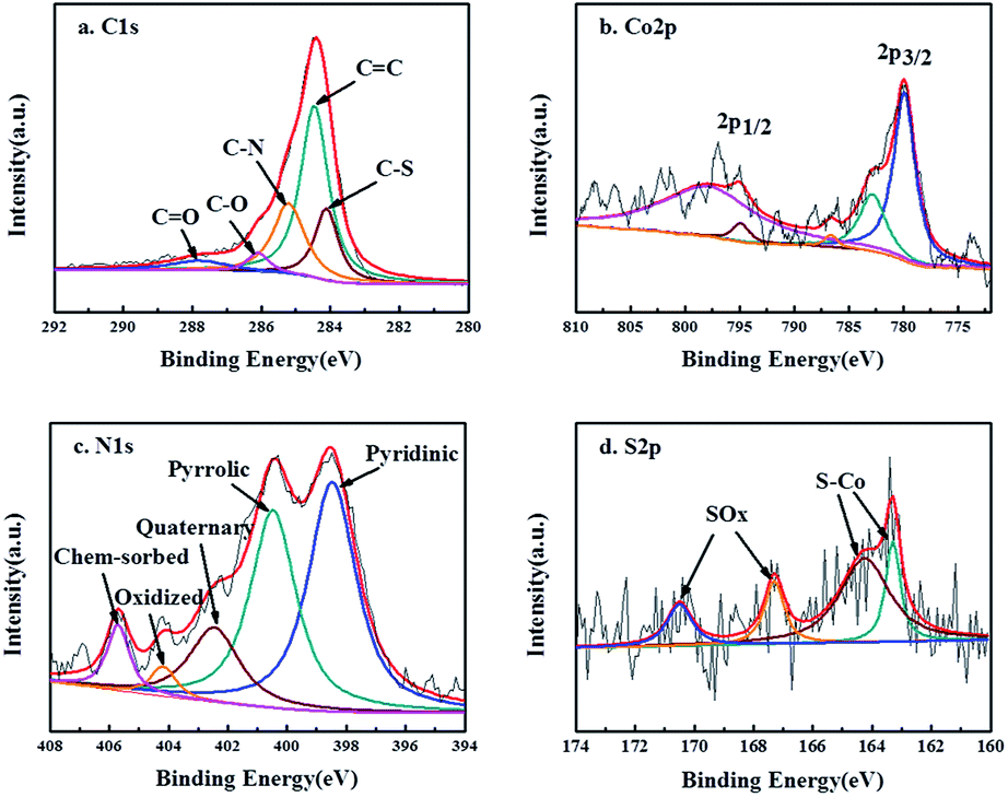 | ||
| Fig. 3 C 1s (a), Co 2p (b), N 1s (c) and S 2p (d) XPS spectra of Co9S8@N/S–CT sample. | ||
To investigate the electrochemical oxygen reduction performance of the as-prepared Co9S8@N/S–CT catalyst, cyclic voltammograms (CVs) in N2-, air- and O2-saturated 0.1 M KOH solution were measured. Distinct ORR peaks were observed at 0.78 and 0.81 V, respectively, from the CVs in O2-saturated KOH solution of Co9S8@N/S–CT and commercial Pt/C (see Fig. S6 and S7†). The closeness of the reductive peak potential for Co9S8@N/S–CT with Pt/C strongly indicated its latent high ORR activity. Further evaluation of ORR activity was conducted on RDE in 0.1 M KOH solution under O2 saturation with linear sweep voltammograms (LSVs) results, as demonstrated in Fig. 4a. The Co9S8@N/S–CT composite showed a negative shift of the onset potential by ∼39 mV in comparison with commercial Pt/C and similar limiting current density, which reaches 78% of that of Pt/C. Especially, the Co9S8@N/S–CT composite shows higher ORR activity compared to N/S–CNF, indicating that the interaction between Co9S8 and carbon tubes further enhanced the ORR activity. Besides, nitrogen and sulfur doping make the carbon tubes grown from CNF more propitious to ORR catalysis.48,49 As evidenced by CVs and LSVs, Co9S8@N/S–CT exhibits comparative ORR activity to commercial Pt/C, which can be attributed to Co9S8 active sites and the nitrogen/sulfur co-doped carbon tubes. In addition to electrochemical activity, durability is another crucial factor for practical utilization of the catalysts. To this end, long-term stability of Co9S8@N/S–CT and commercial Pt/C were compared using chronoamperometry responses with the constant potential of 0.4 V vs. RHE in O2-saturated 0.1 M KOH aqueous solution. Fig. 4b shows that the reductive current density of Co9S8@N/S–CT catalyst kept with approximately 3.0 mA cm−2 after 35000 s of successive testing, which indicates that almost 80% of the beginning current was maintained. In contrast, only 50% of the beginning current density was retained for the Pt/C commercial catalyst. These results demonstrate that the Co9S8@N/S–CT catalyst, which is consist of Co9S8 active sites incorporated with N/S co-doped carbon tubes grown on 3D nanostructural carbon framework, has a superior stability over commercial Pt/C catalysts under alkaline environment. It implied that the unique nanostructure of Co9S8@N/S–CT composite protects the catalytic sites of Co9S8 and enhances the long-term stability. Notably, the Co9S8@N/S–CT can achieve round 78% of the catalytic performance of commercial Pt/C, which is to date the most active ORR catalysts but much more expensive. Furthermore, it preserves a superior long-time stability compared to Pt/C. Thus, the Co9S8@N/S–CT is an efficient ORR catalyst which can be a promising alternative to precious Pt/C for practical application.
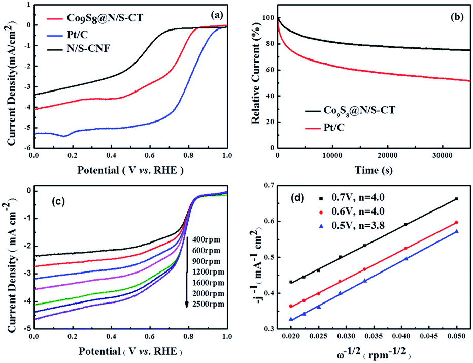 | ||
| Fig. 4 (a) LSVs of Co9S8@N/S–CT, N/S–CNF and Pt/C catalysts drop casted on RDE in O2-saturated 0.1 M KOH with a rotation rate of 1600 rpm and a scan rate of 10 mV s−1. (b) i–t curves of Co9S8@N/S–CT and Pt/C catalysts in O2-saturated 0.1 M KOH with a rotation rate of 1600 rpm and the applied potential of 0.4 V vs. RHE. (c) Polarization curves of Co9S8@N/S–CT in O2-saturated 0.1 M KOH with a scan rate of 5 mV s−1 at various rotation rates. (d) K–L plots for Co9S8@N/S–CT with j−1 versus ω−1/2 at the potential of 0.5, 0.6 and 0.7 V. | ||
For the insight of ORR kinetics, polarization curves of Co9S8@N/S–CT were recorded at various rotation rates on RDE as displayed in Fig. 4c (corresponding results of Pt/C was shown in Fig. S8a†). The LSVs showed representative increasing current density with higher rotation speeds. It is attributed to the fact that the flow rate of oxygen is increased and the diffusion distance is shortened at high speeds.50,51 To quantitatively understand ORR activities of Co9S8@N/S–CT, the transferred electron numbers per oxygen molecule were estimated by analyzing K–L plots, and plotted as a function of potential. Fig. 4d presented the corresponding K–L plots (j−1 vs. ω−1/2) at 0.5, 0.6 and 0.7 V. The good linearity and parallelism in all cases indicates first-order reaction kinetics toward molecular oxygen. As shown in Fig. 4d, the electron transfer numbers per oxygen molecule in ORR for Co9S8@N/S–CT are 4.0, 4.0 and 3.8, which correspond to 0.7, 0.6 and 0.5 V, respectively. The comparative K–L plots of the commercial Pt/C catalyst were depicted in Fig. S8b.† It can be found that electron transfer number of Co9S8@N/S–CT was nearly the same as Pt/C catalyst (≈4). It is generally recognized that a four-electron ORR is the favorable reaction pathway for a PEMFC. Namely, the Co9S8@N/S–CT composite conducts the four-electron ORR pathway is fully demonstrated its favorability for ORR catalysis.
4 Conclusions
In summary, we have successfully developed a green, effective and simple approach for the preparation of Co9S8 activated N/S co-doped carbon tubes in situ grown on 3D CNF network through two steps of impregnation and direct pyrolysis. It was observed that the heating rate affects the preparation of the materials at high temperature. By changing the heating rate, the as-prepared Co9S8@N/S–CT has a totally different morphology, composition, structure and electrochemical catalytic performance compared with other materials derived from BC. The resulting Co9S8@N/S–CT, as a lower-cost non-precious catalyst, has a novel microstructure and exhibits comparable catalytic performance and superior durability towards the oxygen reduction reaction, which is attributed to the synergistic catalytic effect stemming from Co9S8 and nitrogen/sulfur co-doped carbon tubes. The intimate contact between Co9S8 active sites and the highly conductive heteroatom-doped carbon tubes enlarge the specific surface area and increase the graphitization degree of the Co9S8@N/S–CT, which facilitates both mass transport and electron transfer. The enhanced catalytic property combined with its low cost and facile synthesis suggests that Co9S8@N/S–CT can be a promising alternative to noble catalysts for applications in fuel cells and metal air batteries.Acknowledgements
We acknowledge the National Natural Science Foundation of China (Grant No. 21576028 and 51308043) for funding of this work.Notes and references
- H. Hu, L. Han, M. Z. Yu, Z. Y. Wang and X. W. Lou, Energy Environ. Sci., 2016, 9, 107–111 CAS.
- S. Dou, L. Tao, J. Huo, S. Y. Wang and L. M. Dai, Energy Environ. Sci., 2016, 9, 1320–1326 CAS.
- M. Zeng and Y. G. Li, J. Mater. Chem. A, 2015, 3, 14942–14962 CAS.
- M. K. Debe, Nature, 2012, 486, 43–51 CrossRef CAS PubMed.
- J. Qi, L. Xin, Z. Y. Zhang, K. Sun, H. Y. He, F. Wang, D. Chadderdon, Y. Qiu, C. H. Liang and W. Z. Li, Green Chem., 2013, 15, 1133–1137 RSC.
- L. M. Dai, Y. H. Xue, L. T. Qu, H. J. Choi and J. B. Baek, Chem. Rev., 2015, 115, 4823–4892 CrossRef CAS PubMed.
- Y. Jiao, Y. Zheng, M. Jaroniec and S. Z. Qiao, Chem. Soc. Rev., 2015, 44, 2060–2086 RSC.
- S. L. Candelaria, Y. Shao, W. Zhou, X. Li, J. Xiao, J. G. Zhang, Y. Wang, J. Liu, J. Li and G. Cao, Nano Energy, 2012, 1, 195–220 CrossRef CAS.
- B. Y. Xia, H. B. Wu, X. Wang and X. W. Lou, Angew. Chem., Int. Ed., 2013, 52, 12337–12340 CrossRef CAS PubMed.
- Y. Nie, L. Li and Z. D. Wei, Recent Advancements in Pt and Pt-free Catalysts for Oxygen Reduction Reaction, Chem. Soc. Rev., 2015, 44, 2168–2201 RSC.
- G. Wu, K. L. More, C. M. Johnston and P. Zelenay, Science, 2011, 332, 443–447 CrossRef CAS PubMed.
- M. Lefevre, E. Proietti, F. Jaouen and J. P. Dodelet, Science, 2009, 324, 71–74 CrossRef CAS PubMed.
- S. H. Liu, Y. F. Dong, C. T. Zhao, Z. B. Zhao, C. Yu, Z. Y. Wang and J. S. Qiu, Nano Energy, 2015, 12, 578–587 CrossRef CAS.
- D. H. Deng, L. Yu, X. Q. Chen, G. X. Wang, L. Jin, X. L. Pan, J. Deng, G. Q. Sun and X. H. Bao, Angew. Chem., Int. Ed., 2013, 52, 371–375 CrossRef CAS PubMed.
- R. T. Olsson, M. A. S. A. Samir, G. Salazar-Alvarez, L. Belova, V. Strom, L. A. Berglund, O. Ikkala, J. Nogues and U. W. Gedde, Nat. Nanotechnol., 2010, 5, 584–588 CrossRef CAS PubMed.
- Z. Y. Wu, C. Li, H. W. Liang, J. F. Chen and S. H. Yu, Angew. Chem., Int. Ed., 2013, 52, 2925–2929 CrossRef CAS PubMed.
- H. Yano, J. Sugiyama, A. N. Nakagaito, M. Nogi, T. Matsuura, M. Hikita and K. Handa, Adv. Mater., 2005, 17, 153–155 CrossRef CAS.
- M. Iguchi, S. Yamanaka and A. Budhiono, J. Mater. Sci., 2000, 35, 261–270 CrossRef CAS.
- T. N. Ye, L. B. Lv, X. H. Li, M. Xu and J. S. Chen, Angew. Chem., Int. Ed., 2014, 53, 6905–6909 CrossRef CAS PubMed.
- G.-L. Cao, Y.-M. Yan, T. Liu, D. Rooney, Y.-F. Guo and K.-N. Sun, Carbon, 2015, 94, 680–686 CrossRef CAS.
- T. Liu, Y.-F. Guo, Y.-M. Yan, F. Wang, C. Deng, D. Rooney and K.-N. Sun, Carbon, 2016, 106, 84–92 CrossRef CAS.
- M.-R. Gao, Y.-F. Xu, J. Jiang and S.-H. Yu, Chem. Soc. Rev., 2013, 42, 2986–3017 RSC.
- G. Wu, H. T. Chung, M. Nelsona, K. Artyushkovab, K. L. Morec, C. M. Johnstona and P. Zelenaya, ECS Trans., 2011, 41, 1709–1717 CAS.
- R.-C. Jin, J.-H. Zhou, Y.-H. Guan, H. Liu and G. Chen, J. Mater. Chem. A, 2014, 2, 13241–13244 CAS.
- J. Xu, Q.-F. Wang, X.-W. Wang, Q.-Y. Xiang, B. Liang, D. Chen and G.-Z. Shen, ACS Nano, 2013, 7, 5453–5462 CrossRef CAS PubMed.
- I. Bezverkhyy, P. Afanasiev and M. Danot, J. Phys. Chem. B, 2004, 108, 7709–7715 CrossRef CAS.
- Z. Wang, L. Pan, H. Hu and S. Zhao, CrystEngComm, 2010, 12, 1899–1904 RSC.
- S. Chang, M. Lu, Y. Tung and H. Tuan, ACS Nano, 2013, 7, 9443–9451 CrossRef CAS PubMed.
- L. L. Feng, G. D. Li, Y. Liu, Y. Wu, H. Chen, Y. Wang, Y. C. Zou, D. Wang and X. Zou, ACS Appl. Mater. Interfaces, 2015, 7, 980–988 CAS.
- J. Yang, G. X. Zhu, Y. J. Liu, J. X. Xia, Z. Y. Ji, X. P. Shen and S. K. Wu, Adv. Funct. Mater., 2016, 26, 4712–4721 CrossRef CAS.
- L. L. Feng, M. H. Fan, Y. Y. Wu, Y. P. Liu, G. D. Li, H. Chen, W. Chen, D. J. Wang and X. X. Zou, J. Mater. Chem. A, 2016, 4, 6860–6867 CAS.
- Y. L. Zhou, D. Yan, H. Y. Xu, J. K. Feng, X. L. Jiang, J. Yue, J. Yang and Y. T. Qian, Nano Energy, 2015, 12, 528–537 CrossRef CAS.
- H. B. Geng, J. Yang, Z. F. Dai, Y. Zhang, Y. Zheng, H. Yu, H. W. Wang, Z. Z. Luo, Y. Y. Guo, Y. F. Zhang, H. S. Fan, X. L. Wu, J. W. Zheng, Y. G. Yang, Q. Y. Yan and H. W. Gu, Small, 2017, 1603490 CrossRef PubMed.
- R. Li, Y. Dai, B. B. Chen, J. L. Zou, B. J. Jiang and H. G. Fu, J. Power Sources, 2016, 307, 1–10 CrossRef CAS.
- M. Li, H. H. Zhou, W. J. Yang, L. Chen, Z. Huang, N. S. Zhang, C. P. Fu and Y. F. Kuang, J. Mater. Chem. A, 2017, 5, 1014–1021 CAS.
- G. L. Tian, M. Q. Zhao, D. S. Yu, X. Y. Kong, J. Q. Huang, Q. Zhang and F. Wei, Small, 2014, 10, 2251–2259 CrossRef CAS PubMed.
- X. Wang, Q. Li, H. Pan, Y. Lin, Y. Ke, H. Sheng, M. T. Swihart and G. Wu, Nanoscale, 2015, 7, 20290–20298 RSC.
- Y. S. Jun, W. H. Hong, M. Antonietti and A. Thomas, Adv. Mater., 2009, 21, 4270–4274 CrossRef CAS.
- A. Fischer, J. O. Muller, M. Antonietti and A. Thomas, ACS Nano, 2008, 2, 2489–2496 CrossRef CAS PubMed.
- K. Barman and K. K. Nanda, Dalton Trans., 2016, 45, 6352–6356 RSC.
- B. Jeong, D. Shin, J. K. Lee, D. H. Kim, Y. D. Kim and J. Lee, Phys. Chem. Chem. Phys., 2014, 16, 13807–13813 RSC.
- Y. H. Su, Y. H. Zhu, H. L. Jiang, J. H. Shen, X. L. Yang, W. J. Zou, J. D. Chen and C. Z. Li, Nanoscale, 2014, 6, 15080–15089 RSC.
- Y. Q. Chang, F. Hong, C. X. He, Q. L. Zhang and J. H. Liu, Adv. Mater., 2013, 25, 4794–4799 CrossRef CAS PubMed.
- S. Chang, M. Lu, Y. Tung and H. Tuan, ACS Nano, 2013, 7, 9443–9451 CrossRef CAS PubMed.
- H. Zhu, J. Zhang, R. Yanzhang, M. Du, Q. Wang, G. Gao, J. Wu, G. Wu, M. Zhang, B. Liu, J. Yao and X. Zhang, Adv. Mater., 2015, 27, 4752–4759 CrossRef CAS PubMed.
- S. A. Wohlgemuth, R. J. White, M. G. Willinger, M. M. Titirici and M. Antonietti, Green Chem., 2012, 14, 1515–1523 RSC.
- Z. H. Sheng, L. Shao, J. J. Chen, W. J. Bao, F. B. Wang and X. H. Xia, ACS Nano, 2011, 5, 4350–4358 CrossRef CAS PubMed.
- J. T. Zhang, Z. H. Zhao, Z. H. Xia and L. M. Dai, Nat. Nanotechnol., 2015, 10, 444–452 CrossRef CAS PubMed.
- K. P. Gong, F. Du, Z. H. Xia, M. Durstock and L. M. Dai, Science, 2009, 323, 760–764 CrossRef CAS PubMed.
- P. Chen, L. K. Wang, G. Wang, M. R. Gao, J. Ge, W. J. Yuan, Y. H. Shen, A. J. Xie and S. H. Yu, Energy Environ. Sci., 2014, 7, 4095–4103 CAS.
- Q. G. He, Q. Li, S. Khene, X. M. Ren, F. E. Lopez-Suarez, D. Lozano-Castello, A. Bueno-Lopez and G. Wu, J. Phys. Chem. C, 2013, 117, 8697–8707 CAS.
Footnote |
| † Electronic supplementary information (ESI) available. See DOI: 10.1039/c7ra04127f |
| This journal is © The Royal Society of Chemistry 2017 |