DOI:
10.1039/C7RA04105E
(Paper)
RSC Adv., 2017,
7, 28647-28654
Cation substitution induced novel gehlenite Ca2GaAlSiO7:Eu2+/Ce3+ phosphor with green/blue emission for UV-WLEDs†
Received
11th April 2017
, Accepted 16th May 2017
First published on 1st June 2017
Abstract
By partially substituting Ga3+ ions at Al1(2a) and Al2/Si1(4e) sites in gehlenite Ca2Al2SiO7, novel Ca2GaAlSiO7:Eu2+/Ce3+ phosphors with efficient green and blue emissions have been prepared for the first time. Structure and luminescence properties of these newly obtained samples have been investigated in detail together with the effect of Ga3+ substitution which has caused a decrement of Eu–O bond length and covalency. The excitation spectra suggested that both the Eu2+ and Ce3+ doped Ca2GaAlSiO7 samples had broad excitation bands in the UV range, which are favourable properties for application as UV-WLED phosphors. Under 350 nm irradiation, the Ca2GaAlSiO7:Eu2+ had intense emission peaking at 510 nm, while Ca2GaAlSiO7:Ce3+ emitted bright blue light. The energy migration mechanism of the Eu2+ ions was confirmed to be electric dipole–dipole interaction in terms of the experimental results and analysis. The thermal quenching mechanism, and quantum efficiency of the composition-optimized samples have been investigated. Moreover, a white LED device has been obtained by coating our prepared phosphors with CaAlSiN3 red phosphor on a UV chip. The experimental results suggested that the Ca2GaAlSiO7:Eu2+ and Ca2GaAlSiO7:Ce3+ samples might have potential value in serving as green and blue phosphors for UV-WLEDs, respectively.
1. Introduction
In recent decades, the environmental and energy issues have become more and more severe, which make the population of WLEDs (white light emitting diodes) become urgent since they have many advantages over traditional lighting, for example, good reliability, high brightness and long service time.1–5 Currently, a phosphor-converted WLED is the main approach to realize white light, in which the phosphor serves as the key material for governing the colour characteristics.6–9 In the commercial market, the most popular fabrication of WLEDs is InGaN blue-emitting chips, coating with yellow-emitting YAG:Ce. However, this combination faces the problems of low colour rendering index (CRI < 75) and high correlated colour temperature (CCT ≈ 6000 K) resulting from the shortage of emission in the red region, which has a restriction on application in medical and indoor lighting. Researchers have made many efforts to solve this problem, such as improving the red component of YAG:Ce phosphor10,11 and developing novel red phosphors (Sr[Mg3SiN4]:Eu2+,12 Sr[LiAl3N4]:Eu2+,13 K2SiF6:Mn4+ (ref. 14)) which can mix with YAG:Ce. Nowadays, with the development of chips, the realization of white light by UV-A (315–400 nm) chips coating with tri-colour phosphors was expected to dominate the market since the improved CRI can make the light be warmer and more similar to natural light.15,16 Moreover, since the UV light is invisible to naked eye, the performance of WLEDs in this combination strongly depends on the emission spectra of phosphors, making the luminescence properties easy to control. In this way, it is urgently needed to search for new phosphors matching well with the commercial UV chips to meet the requirement of warm white light.
Novel emission phosphors can be sought in a variety ways, e.g., exploring new host through single-particle-diagnosis approach,17 utilizing energy transfer between different dopants,18 designing isostructural solid solutions,19,20 and adjusting the metal–ligand hybridization and crystal field splitting by cationic/anionic substitutions. The ionic substitution of host frequently employed in Ce3+ and Eu2+ ions doped phosphors since the energy levels of outmost 5d orbits are easily affected by the coordination environment. Moreover, the spin- and orbit-allowed electron transition results in intense luminescence intensity which is one of the key factors for application. Li et al. had obtained different emission colours with Ba2+ substituting for Sr2+ in Sr2Si2O2N2:Eu.21 Won Bin Im had reported green phosphors with different CIE coordinates by substituting Ba2+ for Sr2+ ion in Sr3Ce0.025AlO4F.22 Among many kinds of inorganic materials, aluminosilicate-based phosphors have been investigated due to their relatively easy preparation, structural diversity, and good thermal stability. In 1982, M. Kimata investigated the structure of Ca2Al2SiO7 gehlenite in detail.23 Qiu and Wang et al. reported luminescence property of Eu2+ and Ce3+/Tb3+ ion in this host, respectively.24,25 Wang et al. obtained yellowish green emission by substituting Sr2+ for Ca2+ ions Ca2Al2SiO7:Eu2+.26 Xia et al. obtained solid solution by substituting Mg2+–Si4+ for Al3+–Al3+ in Ca2Al2SiO7.27 As we know that the Ga3+ ion has similar property with Al3+ due to their same valence states and outmost electron configurations. The Ga3+ ions can be used to tune the emission wavelength and improve the luminescence performance of phosphors, for example, the commercial green Y3(Al,Ga)5O12:Ce3+ and Y3(Al,Ga)5O12:Tb3+ phosphors. Moreover, the gallate based oxides had been proved to be good host materials for phosphor.28,29 In this work, by partially substituting Ga3+ for Al3+ ions, we firstly obtained the Ca2GaAlSiO7 which can be expressed as Ca2Al0.5Ga0.5(Al0.5Ga0.5Si)O7 according to their wyckoff positions. The structure and luminescence properties of Eu2+ and Ce3+ ions in the host had been investigated as well as the effect of Ga3+ substitution. The performance of our prepared phosphors has great attraction for UV-WLEDs.
2. Experimental section
2.1 Starting materials and synthesis
Series of Ca2GaAlSiO7:xEu2+/yCe3+,yLi+ (CGASO:xEu2+/yCe3+,yLi+) samples had been prepared via common solid-state reactions. The starting materials CaCO3 (A.R.), Ga2O3 (A.R.), Al2O3 (A.R.), SiO2 (A.R.), Li2CO3(A.R.), CeO2 (99.99%) and Eu2O3 (99.99%) were firstly weighed on analytical balance in accordance with the molar ratio of each element in the formula. Since the valence states between Ca2+ and Ce3+ are different, the addition of charge compensators becomes necessary. Thus, the Li2CO3 providing Li+ ions were added during the preparation. Raw materials with proper ratio were well mixed by thoroughly grinding for 15 min. After that, the mixtures were sintered at 1300 °C for 3 h under reductive atmosphere (20% H2 + 80% N2) to form the as-prepared phosphors.
2.2 Characterization techniques
Phase identification of our as-prepared phosphors was confirmed by powder XRD analysis operated on AXS D8 (Bruker) with radiation of CuKα (λ = 0.15405 nm) at 40 kV and 40 mA. The photoluminescence emission and excitation spectra were collected on Hitachi fluorescence spectrophotometer (F-7000) with excitation source being 150 W xenon lamp. Diffuse reflectance spectra measurement was performed on Hitachi spectrophotometer (U-4100-UV/Vis) using BaSO4 as standard reference. For the luminescence dynamic measurement, the signals were collected on digital oscilloscope (Lecroy Wave Runner 6100, 1 GHz) with tunable laser serving as excitation source (pulse width: 4 ns, gate: 50 ns). Photoluminescence quantum yield (QY) of our prepared samples was collected on C9920-02 absolute quantum yield system (Hamamatsu Photonics K.K., Japan). The spectra at different temperatures were operated on Edinburgh Instrument spectrophotometer (FLS 920) equipped with temperature controller. The EL spectrum, CIE coordinates, colour rendering index (CRI), and colour temperature (CCT) of the fabricated LED device were measured by Starspec SSP6612.
3. Results and discussion
3.1 Phase analysis
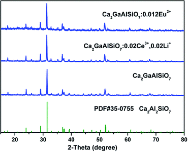
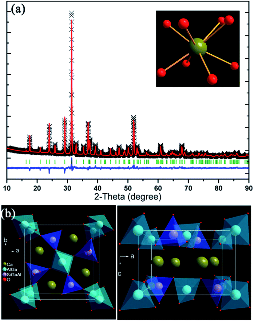
Phase purity of our prepared phosphors is checked by powder X-ray diffraction and the typical patterns have been shown in Fig. 1. The diffraction peaks of Ca2GaAlSiO7 host and rare earth ions doped samples match well with the standard data of Ca2Al2SiO7 (JCPDS#35-0755) which is shown as a comparison. The results reveal that the as-prepared samples are single phase and have same structure with Ca2Al2SiO7. Since the ionic radius of Ga3+ (r = 0.47 Å, CN = 4) is much larger than that of Al3+ ion (r = 0.39 Å, CN = 4), the substitution of Ga3+ has caused the diffraction peaks shift to lower angle as can be seen in Fig. S1 (ESI†). Considering the similar ionic radii, the doped rare earth ions are thought to occupy the site of Ca2+ ions. Due to the different valence between Ce3+ and Ca2+, the doping of Ce3+ will lead to positive charges in the host, which can affect stability and luminescence intensity of the phosphor. To solve this problem, the Li+ ions serving as charge compensators were added along with Ce3+ ions. In the host, one Ce3+ ion and one Li+ ion are considered to replace two Ca2+ ions, which can be demonstrated as 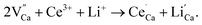 From Fig. 1, we can see the Ca2+ sites in the lattice are substituted by the doped ions without causing any impurity.
 |
| | Fig. 1 Powder X-ray diffraction patterns of typical prepared samples. The standard data of Ca2Al2SiO7 (JCPDS#35-0755) are shown as references. | |
Rietveld structure refinement of the Ca2GaAlSiO7 host has been conducted using the crystal structure parameters of Ca2Al2SiO7 as initial structure model. The refinement results are listed in Table 1 and the refined XRD profiles together with crystal structures are demonstrates Fig. 2. The Ca2GaAlSiO7 host possesses tetrahedral crystal system and P![[4 with combining macron]](https://www.rsc.org/images/entities/char_0034_0304.gif) 21m (113) space group. In the lattice, the Ca2+ site is coordinated by eight oxygen ions forming polyhedron, which can be substituted by Eu2+/Ce3+ ion forming emission centre. The Ga3+, Al3+ and Si4+ cations are 4-fold coordinated and form [GaO4], [AlO4] and [SiO4] tetrahedrons, respectively. These tetrahedrons are further connected by sharing oxygen atoms. The 2a sites are occupied by Ga3+ and Al3+ ions with the ratio of 1
21m (113) space group. In the lattice, the Ca2+ site is coordinated by eight oxygen ions forming polyhedron, which can be substituted by Eu2+/Ce3+ ion forming emission centre. The Ga3+, Al3+ and Si4+ cations are 4-fold coordinated and form [GaO4], [AlO4] and [SiO4] tetrahedrons, respectively. These tetrahedrons are further connected by sharing oxygen atoms. The 2a sites are occupied by Ga3+ and Al3+ ions with the ratio of 1![[thin space (1/6-em)]](https://www.rsc.org/images/entities/char_2009.gif) :1, while the 4e sites are occupied with Ga3+:Al3+:Si4+ = 1:1:2. The fit quality of this refinement is pretty good which can be reflected from reliability results χ2 = 2.649, Rwp = 7.35%, Rp = 5.63%. The cell parameters of our prepared Ca2GaAlSiO7 are determined to be a = b = 7.7441(2) Å, c = 5.1039(2) Å and V = 306.08(1) Å3, while the standard lattice parameters of Ca2Al2SiO7 reported by M. Kimata are a = b = 7.6770(3) Å, c = 5.0594(3) Å and V = 298.18(2) Å3. The expansion of cell volume for as-prepared Ca2GaAlSiO7 can be ascribed to large radius of Ga3+ than Al3+ ions. Moreover, the average length of Ca–O bond was determined to be 2.548(6) Å in Ca2GaAlSiO7 host, which is shorter than that in Ca2Al2SiO7 (Ca–O: 2.563 Å). This phenomenon can be ascribed to that the substitution of Ga3+ for Al3+ ions will increase the lattice strain due to the cation size mismatch. And thus, the anion clusters in the host will reduce this strain by shorting the cation–anion (Ca–O) distance.30
:1, while the 4e sites are occupied with Ga3+:Al3+:Si4+ = 1:1:2. The fit quality of this refinement is pretty good which can be reflected from reliability results χ2 = 2.649, Rwp = 7.35%, Rp = 5.63%. The cell parameters of our prepared Ca2GaAlSiO7 are determined to be a = b = 7.7441(2) Å, c = 5.1039(2) Å and V = 306.08(1) Å3, while the standard lattice parameters of Ca2Al2SiO7 reported by M. Kimata are a = b = 7.6770(3) Å, c = 5.0594(3) Å and V = 298.18(2) Å3. The expansion of cell volume for as-prepared Ca2GaAlSiO7 can be ascribed to large radius of Ga3+ than Al3+ ions. Moreover, the average length of Ca–O bond was determined to be 2.548(6) Å in Ca2GaAlSiO7 host, which is shorter than that in Ca2Al2SiO7 (Ca–O: 2.563 Å). This phenomenon can be ascribed to that the substitution of Ga3+ for Al3+ ions will increase the lattice strain due to the cation size mismatch. And thus, the anion clusters in the host will reduce this strain by shorting the cation–anion (Ca–O) distance.30
Table 1 Final refined structure parameters of CGASO host derived from the Rietveld refinement of X-ray diffraction dataa
| Atom |
Site |
x |
y |
z |
Frac |
Uiso |
| Cell parameters: a = 7.7441(2) Å, b = 7.7441(2) Å, c = 5.1039(2) Å, α = β = γ = 90°, V = 306.08(1) Å3; Z = 2; space group: P21m (113); reliability factors: χ2 = 2.649, Rwp = 7.35%, Rp = 5.63% Average {Ca}–O bond length: 2.548(6) Å. |
| Ca1 |
4e |
0.3397(8) |
0.1602(2) |
0.5092(5) |
1.00 |
0.0119(7) |
| Ga1 |
2a |
0.00000 |
0.00000 |
0.0000 |
0.50 |
0.02500 |
| Ga2 |
4e |
0.14310 |
0.35690 |
0.95630 |
0.25 |
0.02500 |
| Al1 |
2a |
0.00000 |
0.00000 |
0.00000 |
0.5 |
0.02500 |
| Al2 |
4e |
0.14310 |
0.35690 |
0.95630 |
0.25 |
0.02500 |
| Si1 |
4e |
0.14310 |
0.35690 |
0.95630 |
0.5 |
0.02500 |
| O1 |
2c |
0.50000 |
0.00000 |
0.17590 |
1.00 |
0.02500 |
| O2 |
4e |
0.1477(7) |
0.3523(7) |
0.2863(9) |
1.00 |
0.0164(2) |
| O3 |
8f |
0.0881(6) |
0.1670(6) |
0.7823(8) |
1.00 |
0.0121(1) |
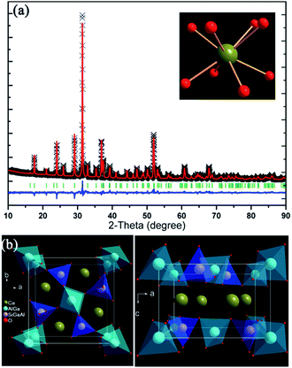 |
| | Fig. 2 (a) Rietveld refinement pattern of CGASO host and the coordinate environment of Ca2+ ion. (b) Unit cell structure of CGASO viewing along c and b direction. | |
3.2 Photoluminescence properties of CGASO:Eu2+ and CGASO:Ce3+,Li+ phosphors
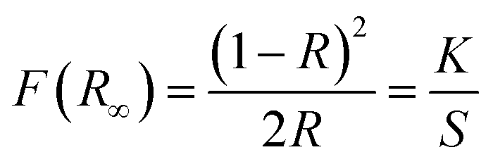
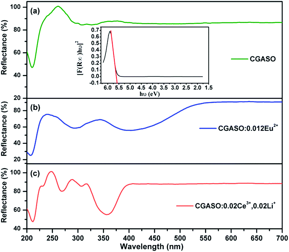
Fig. 3 depicts reflection spectra of our typical prepared samples. For the CGASO host, there is a sharp drop under 230 nm caused by electron transition from valence band (VB) to conduction band (CB) of the host. For rare earth ions doped samples, the reflection spectra exhibit not only the host absorption but also absorption bands arising from 4f → 5d electronic transition of Eu2+ and Ce3+ ions. The absorption band of CGASO:0.012Eu2+ covers the UV and blue region (250–480 nm), while the absorption band of CGASO:0.02Ce3+,0.02Li+ is in the range of 250–400 nm with several peaks. By utilizing the following equation, an approximate band gap value can be obtained:31| | |
[F(R∞)hν]n = A(hν − Eg)
| (1) |
where hν represents the photon energy; Eg is the optical band gap value; n = 1/2 and 2 corresponds for indirect and direct transition, respectively; A stands for a constant; F(R∞) stands for Kubelka–Munk function reported by Kubelka and Munk in 1931, which can be written as32| |
 | (2) |
in which S, K and R represent for coefficients of scattering, absorption and reflection of light energy, respectively. By making [F(R∞)hν]2 plot against energy (hν) and extrapolating to [F(R∞)hν]2 = 0, an intersection between the straight line and the energy axis is obtained and the value at this point is the band gap value. For CGASO host, Eg was calculated to be 5.37 eV.
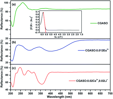 |
| | Fig. 3 Diffuse reflection spectra of (a) CGASO, (b) CGASO:0.012Eu2+ and (c) CGASO:0.02Ce3+,0.02Li+ samples. The inset picture shows the relationship between [F(R∞)hν]2 and hv of the CGASO host. | |
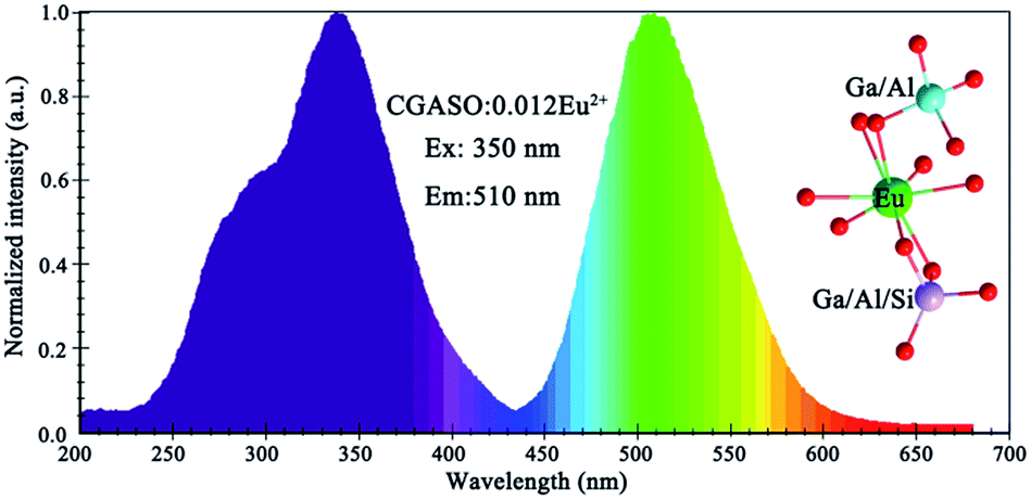
The photoluminescence emission (PL) and excitation (PLE) spectra of as-prepared Eu2+ doped phosphors have been depicted in Fig. 4. The excitation spectrum of CGASO:0.012Eu2+ consists a main band peaking at 350 nm and a shoulder band peaking at 290 nm, resulting from the spin- and orbit-allowed electron transition from 4f7 ground state to 4f65d1 excited state. At the irradiation of 350 nm, the phosphor exhibits a broad emission spectrum with maximum at 508 nm. According to the literatures, energy difference between emission peak wavelength and zero phonon line equals to half of the Stokes shift approximately. Moreover, the energy of zero-phonon line can be estimated from the intersection of the emission and excitation spectra empirically.33–35 For our prepared CGASO:0.012Eu2+ sample, the lowest excited state of 7FJ multiplet of the 4f6 configuration (zero-phonon line) is determined to be 2.85 eV utilizing the interaction point (435 nm) of excitation and emission curves. In this case, energy difference between emission peak and zero-phone line is calculated to be 0.42 eV. Correspondingly, the Stokes shift value for CGASO:Eu2+ sample is estimated to be 0.84 eV. The emission spectra of Ca2(Al,Ga)2SiO7 with different Ga3+ substitution content had been shown in Fig. S2,† from which a blue shift can be observed. As discussed previously, the Ga3+ substitution can make the Eu–O bond length become short since the Eu2+ ions will occupy the Ca2+ site in the lattice. Thus, crystal field splitting of 5d energy level of Eu2+ should become larger since Dq ∝ 1/R5. In this way, a red shift is expected other than a blue shift. However, the emission of Eu2+ is also affected by nephelauxetic effect arising from the covalency between cation and ligands. The electronegativity of Ga (1.81) is higher than that of Al (1.61), which will enlarge the electron-cloud overlap of Ga–O. In this case, the covalency of Eu–O connected in Eu–O–Ga will decrease and finally cause the emission shift to a short wavelength. Thus, the blue shift is the result of both crystal field splitting and nephelauxetic effect due to the decrement of bond length and covalency of Eu–O.
 |
| | Fig. 4 Excitation and emission spectra of CGASO:0.012Eu2+ phosphor. | |
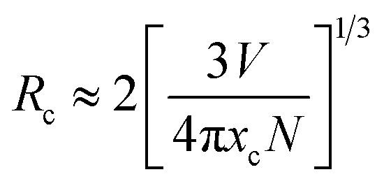
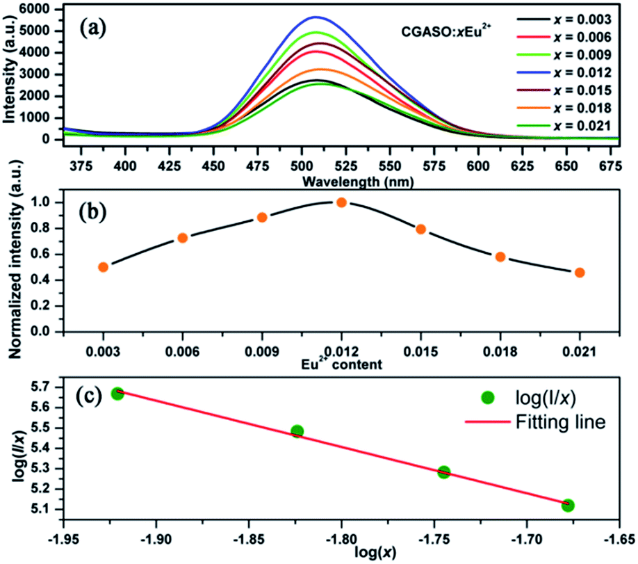
In order to obtain the optimal doping concentration of Eu2+ ions, CGASO:xEu2+ phosphors with x varying from 0.003 to 0.021 have been prepared and measured. From Fig. 5(a) we can see that the emission intensity value of CGASO:Eu2+ experiences a parabolic change in the whole doping range of Eu2+ ions and the maximum emission intensity appears at x = 0.012. The decrement of emission intensity with further increment of Eu2+ content is resulting from concentration quenching effect. The relationship between emission intensity and doping content of phosphors has been depicted in Fig. 5(b) for having an intrusive view. On the basis of Dexter's energy transfer theory, energy migration among the activators appears at high doping content and further results in the concentration quenching. Utilizing the following equation given by G. Blass, critical distance (Rc) for the dopants can be estimated:36
| |
 | (3) |
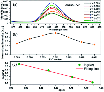 |
| | Fig. 5 (a) Emission spectra of CGASO:xEu2+ (x = 0.003–0.021) samples. (b) Dependence of relative emission intensity of CGASO:xEu2+ phosphors on Eu2+ content. (c) Relationship between log(I/x) and logx. | |
In the above formula, xc stands for critical concentration, V represents the unit cell volume, the N is the number of cation sites that activators can substitute in each unit cell. For CGASO host, N = 4, V = 306.08 Å3 and xc = 0.012. Thus, the value of Rc is obtained as 23.01 Å. For oxide phosphors, multipole–multipole interaction and exchange interaction among the activators are usually responsible for non-radiative energy transfer. However, the exchange interaction can be excluded in our discussion since it only fits the energy transfer of forbidden transitions and occurs with critical distance of activators smaller than 5 Å. As a result, multipole–multipole interaction is the main reason for concentration quenching of the Eu2+ in our prepared phosphor. According to the report of Van Uiter in 1971, the PL intensity (I) per Eu2+ ion in CGASO:Eu2+ phosphor satisfy the equation37,38
| |
 | (4) |
in which
β and
k are constants in a given condition;
θ = 6, 8 and 10 stands for electric dipole–dipole (d–d), dipole–quadrupole (d–q), and quadrupole–quadrupole (q–q) interactions, respectively;
x is the concentration of Eu
2+ ions. To get a precise value of
θ, the relationship between log(
I/
x) and log(
x) is plotted after taking logarithm on
eqn (4). Correspondingly, the value of
θ obtained from the slope of the fitting line as shown in
Fig. 5(c) is found to be 6.63, revealing that the concentration quenching of Eu
2+ ions is mainly resulted from electric dipole–dipole interaction.
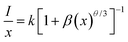
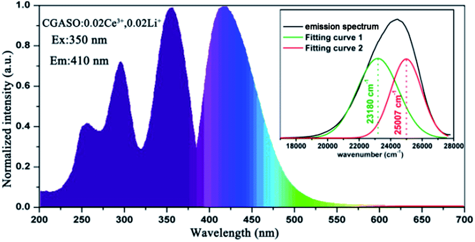
The PL and PLE spectra of CGASO:0.02Ce3+,0.02Li+ phosphor have been shown in Fig. 6. The PLE spectrum with monitor wavelength being 410 nm covers a range from 225 to 375 nm containing three peaks at 254, 293 and 350 nm. This broad excitation band is resulted from spin- and orbit-allowed 4f1 → 4f05d1 electronic transition of the Ce3+ ions in crystal field. The emission peak of CGASO:0.02Ce3+,0.02Li+ locates at 410 nm. Similar with the Eu2+ doped samples, the substitution of Ga3+ for Al3+ ions in Ca2Al2SiO7 host has also caused blue shift of the emission spectra as shown in Fig. S3.† Generally, the ground state of the Ce3+ ions can spilt into two energy levels (2F5/2 and 2F7/2) owing to spin–orbit interaction. As a result, two symmetric bands with energy difference being ∼2000 cm−1 can be obtained by Gaussian decomposition of the emission band.39,40 For our prepared CGASO:0.02Ce3+,0.02Li+ phosphor, wavelength numbers of the two well-separated Gaussian components are 23180 cm−1 and 25007 cm−1 corresponding to 4f05d1 → 2F7/2 and 4f05d1 → 2F5/2 transitions, respectively. The energy difference determined to be 1827 cm−1 agrees well with the theoretical value.
 |
| | Fig. 6 Photoluminescence spectra of CGASO:0.02Ce3+,0.02Li+ sample. The inset shows the Gaussian peaks of the emission spectrum. | |
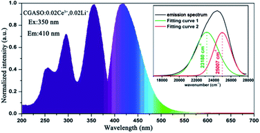
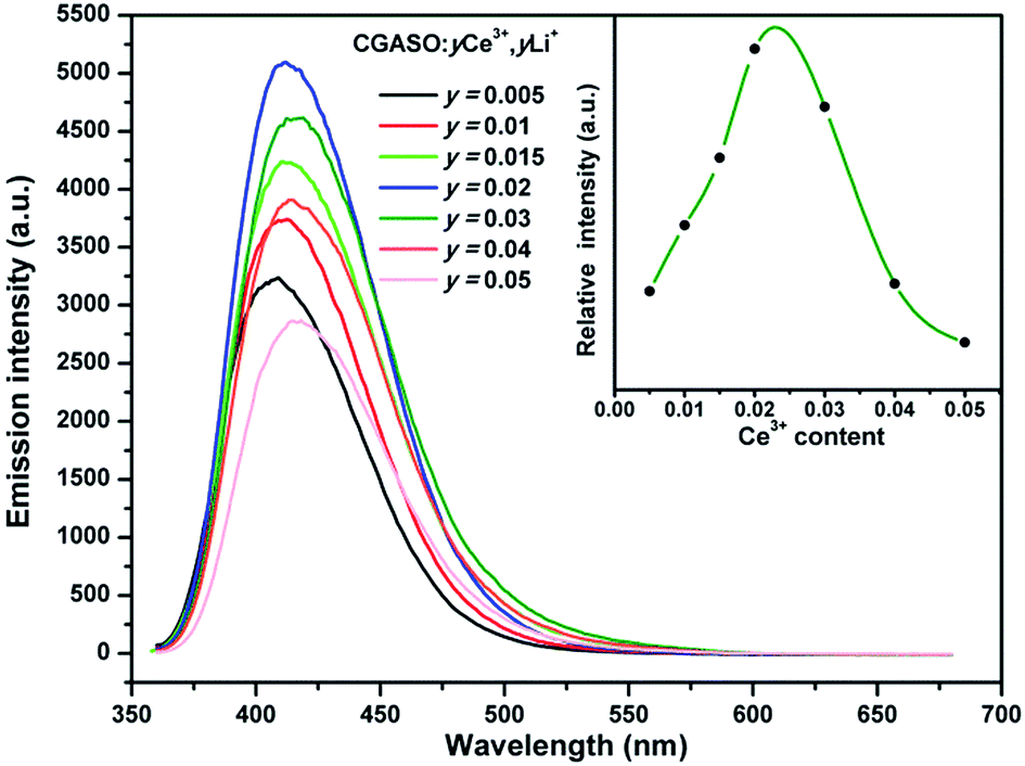
The Ce3+ doped samples with different doping contents had been synthesized and investigated. As shown in Fig. 7, the optimal doping concentration is y = 0.02 for the Ce3+ doped samples. When the value of y is more than 0.02, the energy migration among Ce3+ ions has a negative effect on the emission intensity. The relation between Ce3+ luminescence intensity and its doping concentration has also been illustrated in Fig. 7 for a clearly view. One can also see that the emission spectra have a small red shift with the increment of Ce3+ content, resulting from the variation of the crystal field splitting around Ce3+ ions. Since the Li+ ions codoped with Ce3+ ions have smaller radius than Ca2+ ions, the doping of the Li+ ions can shrinks the CGASO crystal lattice. The variation on crystal volume makes the crystal field strength around the Ce3+ ions enhance and the 5d energy levels of Ce3+ split largely. As a result, the Ce3+ emission shift to longer wavelength. The luminescence spectra indicate that the Ce3+ doped CGASO sample is a potential UV excited blue emission phosphor.
 |
| | Fig. 7 Emission spectra of CGASO:yCe3+,yLi+ (y = 0.005–0.05)phosphors. The inset shows the relationship between emission intensity and doping content of Ce3+ ion. | |
3.3 Luminescence dynamic, thermal stability and CIE coordinates of CGASO:Eu2+ and CGASO:Ce3+,Li+ phosphors
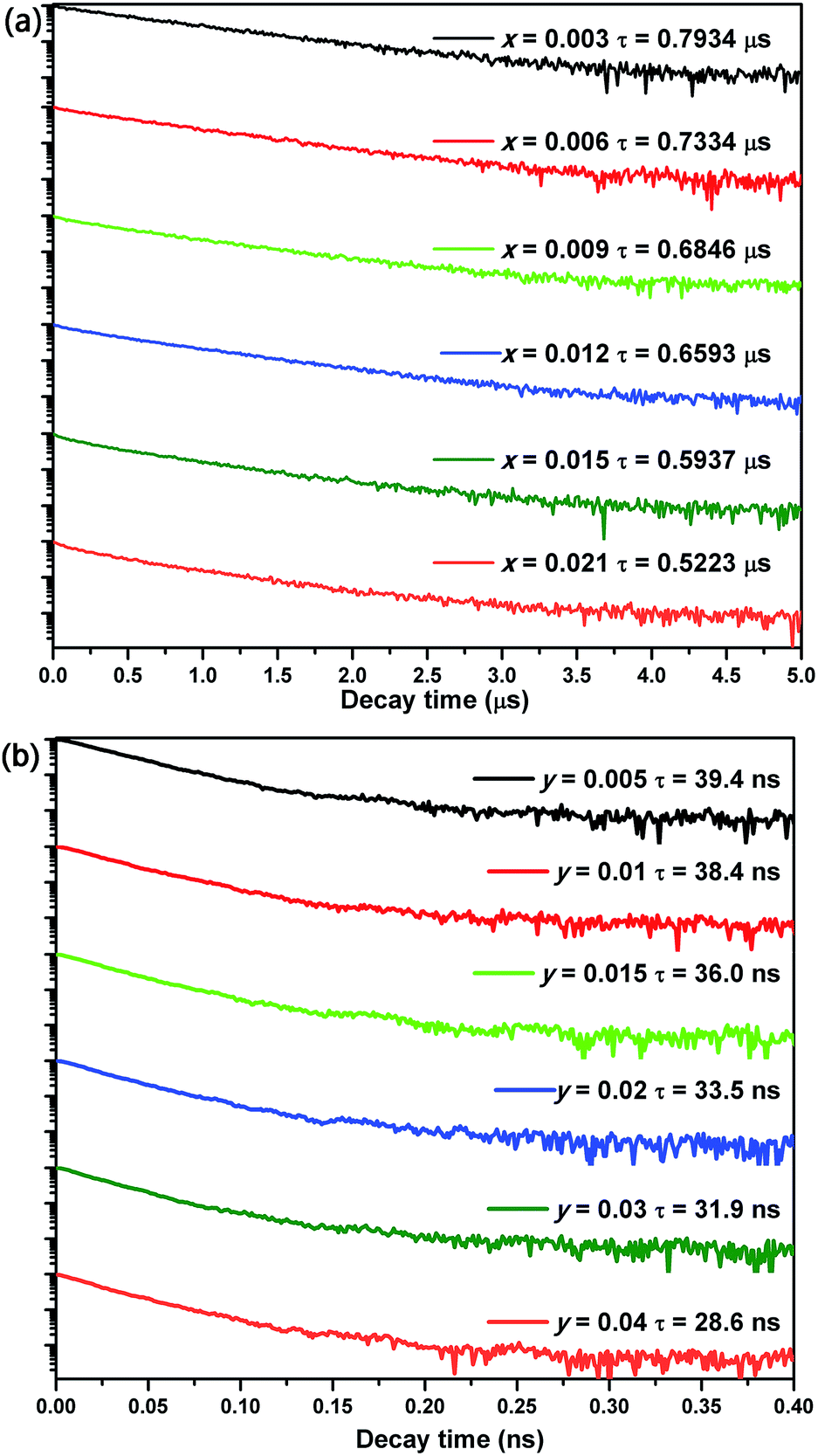
To have an understanding on the luminescence dynamic of the phosphors, the decay curves of CGASO:xEu2+ (λex = 350 nm, λem = 508 nm) and CGASO:yCe3+,yLi+ (λex = 350 nm, λem = 410 nm) samples have been measured and illustrated in Fig. 8. The average lifetimes of the samples can be determined by the following equation:| |
 | (5) |
where I(t) represents the emission intensity of activators at time t. The lifetimes for CGASO:xEu2+ phosphors with x being 0.003, 0.006, 0.009, 0.012, 0.015, and 0.021 were determined to be 0.793, 0.733, 0.685, 0.659, 0.594, and 0.522 μs, respectively. The lifetimes of Ce3+ ions were calculated to be 39.4, 38.4, 36.0 33.5, 31.9, and 28.6 ns for CGASO:yCe3+,yLi+ samples with y = 0.005, 0.01, 0.015, 0.02, 0.03, and 0.04, respectively. In this case, both the increment of Eu2+ and Ce3+ content have decreased the decay lifetime of phosphors, which can be ascribed to the energy transfer among activators.
 |
| | Fig. 8 Decay curves of (a) CGASO:xEu2+ and (b) CGASO:yCe3+,yLi+ phosphors with different doping concentrations. | |
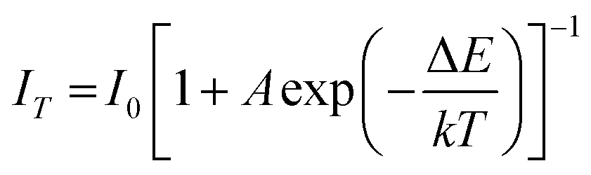
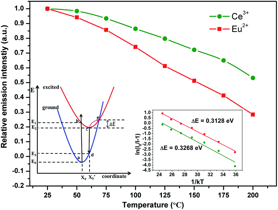
Since the working temperature of WLEDs can reach 150 °C, thermal stability comes to be an important characteristic for phosphors and is always addressed. Fig. 9 shows the normalized emission intensity of CGASO:0.012Eu2+ and CGASO:0.02Ce3+,0.02Li+ phosphors with temperature ranging from 25 to 200 °C (λ = 350 nm). With the increment of temperature, the luminescence intensity of Eu2+ and Ce3+ both decreased gradually owing to thermal quenching. At 150 °C, the luminescence intensity of CGASO:0.012Eu2+ and CGASO:0.02Ce3+,0.02Li decreased to 50.2% and 71.8% of their initial intensity at 25 °C. Generally, there are two models to explain the reason of thermal quenching. One is the autoionization model proposed by Dorenbos,41 the other is configurational diagram as depicted in inset of Fig. 9. The autoionization model has some limitations and is only suitable for the phosphors that the 5d energy level of rare earth ions is close to the conduction band minimum well before the 4f–5d crossing point. The configurational diagram depicts relationship between energy and ionic degrees of freedom for both ground and excited state of a material and is extremely successful in demonstrating various luminescence processes. Here, the latter one is employed to demonstrating the thermal quenching of prepared phosphors. Under UV irradiation, the electrons of activators can be excited from ground state (point a) to excited state (point b). The excited electrons will modify the forces inside the crystal and alter the average atomic positions from X0 to  , leading to the crossing of the 5d and 4f energy curves.42 At low temperature, the excited electrons will go back to ground state with light emission after dissipation some energy through phonon relaxation and the crystal will also returns to its original ground state geometry. However, at high temperature the excited electrons can absorb the phonon energy and be thermally activated to the crossing point. Finally, the electrons at crossing point decay nonradiatively to the ground state, making the thermal quenching appear. This phenomenon will be more severe with temperature increasing. Energy difference between point e and c is called activation energy (ΔE) which affects the thermal stability of phosphors directly. The value of ΔE can be determined by the following modify Arrhenius equation:43
| |
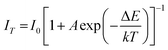 | (6) |
where
I0 the initial emission intensity,
IT stands for the emission intensity at different temperatures,
A is a constant for a given host,
k is the Boltzmann constant (8.629 × 10
−5 eV K
−1). The inset of
Fig. 9 depicted the dependence of ln[(
I0/
IT) − 1] on 1/
kT. According to
eqn (6), the values of Δ
E were calculated to be 0.3128 and 0.3268 eV for CGASO:0.012Eu
2+ and CGASO:0.02Ce
3+,0.02Li
+ samples, respectively.
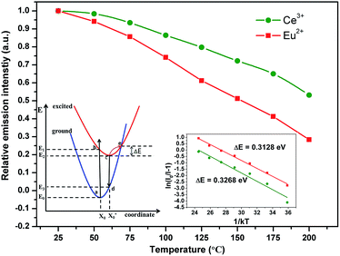 |
| | Fig. 9 Relative emission intensities of CGASO:0.012Eu2+ and CGASO:0.02Ce3+,0.02Li+ samples at different temperatures. The inset depict the configuration coordinate diagram and plots of ln[(I0/IT) − 1] versus 1/kT for CGASO:0.012Eu2+ and CGASO:0.02Ce3+,0.02Li+ samples. | |
Quantum yield (Φ) as an important parameter for the prepared phosphor has been measured by integrated sphere method. Under 350 nm irradiation, quantum yields for CGASO:0.012Eu2+ and CGASO:0.02Ce3+,0.02Li+ samples are 65.0% and 65.2%, respectively. Since the value of quantum yield can be easily affected by the morphology, crystallinity and size of the phosphor, the Φ can be further improved by optimize the preparation condition and phosphor composition. Fig. 10(a) illustrates the Commission International del'Eclairage (CIE) chromaticity coordinates of typical CGASO:0.012Eu2+ and CGASO:0.02Ce3+,0.02Li+ determined by their corresponding PL spectra. For the Eu2+ doped phosphor, the CIE coordinates located in the green region with the value being (0.193, 0.504), which is consistent with its emission colour as can be seen from the digital photograph. The CIE coordinates of CGASO:0.02Ce3+,0.02Li+ was determined to be (0.156, 0.037). The luminescence properties indicate that our prepared CGASO:0.012Eu2+ and CGASO:0.02Ce3+,0.02Li+ phosphors are potential UV light excited green and blue phosphors, respectively. It is known to us that white light can be obtained when mix blue, green and red light at appropriate intensity. To demonstrate the application of prepared phosphors, a white LED device has been fabricated by coating phosphors (CGASO:0.012Eu2+, CGASO:0.02Ce3+,0.02Li+, and CaAlSiN3:Eu2+) on a 365 nm UV chip. The corresponding EL spectrum and digital photograph has been depicted in Fig. 10(b). The Ra and CCT values for the fabricated white LED device with CIE coordinates being (0.359, 0.320) are determined to be 82.1 and 4232 K, respectively.
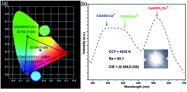 |
| | Fig. 10 (a) CIE coordinates and digital photographs of CGASO:0.012Eu2+ and CGASO:0.02Ce3+,0.02Li+ samples. (b) EL spectrum of a white LED device fabricated by “CGASO:0.012Eu2+ + CGASO:0.02Ce3+,0.02Li+ + red phosphor + 365 nm LED chip”. The inset shows the corresponding LED device photograph. | |
4. Conclusions
To summarize, we have obtained the UV efficiently excited Eu2+ and Ce3+ doped Ca2GaAlSiO7 phosphors firstly by cation substitution. Structure refinement by GSAS indicates that Ca2GaAlSiO7 own tetrahedral crystal system and P21m (113) space group. The Ca2GaAlSiO7:0.012Eu2+ sample emits intense green light with CIE coordinates being (0.193, 0.504) and quantum efficiency being 65.0%, while the emission of Ca2GaAlSiO7:0.02Ce3+,0.02Li+ locates in blue region with CIE coordinates being (0.156, 0.037) and quantum efficiency value being 65.2%. The substitution of Ga3+ for Al3+ has caused a blue shift of emission due to the decrement of cation–ligand distance and covalency. At 150 °C, the emission intensity of CGASO:0.012Eu2+ and CGASO:0.02Ce3+,0.02Li+ decrease to 50.2% and 71.8% of their initial values, respectively. Moreover, a white LED device with Ra = 82.1 and CCT = 4232 K had been fabricated by 365 nm UV chip with our prepared phosphors and commercial red phosphor. The investigation suggests that the Eu2+ and Ce3+ activated samples may be potential green and blue phosphors for UV WLEDs.
Acknowledgements
Our work was financially supported by the National Natural Science Foundation of China (NSFC) (Grant No. 11374132 and 61307067), Natural Science Foundation of Shandong Province (ZR2015JL024) and Taishan Scholars project of Shandong Province (ts201511055).
Notes and references
- X. Wang and Y. Wang, J. Phys. Chem. C, 2015, 119, 16208 CAS.
- H. Lin, J. Xu, Q. Huang, B. Wang, H. Chen, Z. Lin and Y. Wang, ACS Appl. Mater. Interfaces, 2015, 7, 21835 CAS.
- L.-L. Wei, C. C. Lin, Y.-Y. Wang, M.-H. Fang, H. Jiao and R.-S. Liu, ACS Appl. Mater. Interfaces, 2015, 7, 10656 CAS.
- D. F. Sava, L. E. S. Rohwer, M. A. Rodriguez and T. M. Nenoff, J. Am. Chem. Soc., 2012, 134, 3983 CrossRef CAS PubMed.
- D. Hou, C. Liu, X. Ding, X. Kuang, H. Liang, S. Sun, Y. Huang and Y. Tao, J. Mater. Chem. C, 2013, 1, 493 RSC.
- H. Daicho, T. Iwasaki, K. Enomoto, Y. Sasaki, Y. Maeno, Y. Shinomiya, S. Aoyagi, E. Nishibori, M. Sakata and H. Sawa, Nat. Commun., 2012, 3, 1132 CrossRef PubMed.
- J. Y. Han, W. B. Im, G. Lee and D. Y. Jeon, J. Mater. Chem., 2012, 22, 8793 RSC.
- Z. Xia, Z. Xu, M. Chen and Q. Liu, Dalton Trans., 2016, 45, 11214 RSC.
- Z. Xia and Q. Liu, Prog. Mater. Sci., 2016, 84, 59 CrossRef CAS.
- M. Shang, J. Fan, H. Lian, Y. Zhang, D. Geng and J. Lin, Inorg. Chem., 2014, 53, 7748 CrossRef CAS PubMed.
- J. Zhang, L. Wang, Y. Jin, X. Zhang, Z. Hao and X.-j. Wang, J. Lumin., 2011, 131, 429 CrossRef CAS.
- S. Schmiechen, H. Schneider, P. Wagatha, C. Hecht, P. J. Schmidt and W. Schnick, Chem. Mater., 2014, 26, 2712 CrossRef CAS.
- P. Pust, V. Weiler, C. Hecht, A. Tücks, A. S. Wochnik, A.-K. Henß, D. Wiechert, C. Scheu, P. J. Schmidt and W. Schnick, Nat. Mater., 2014, 9, 891–896 CrossRef PubMed.
- H. Zhu, C. C. Lin, W. Luo, S. Shu, Z. Liu, Y. Liu, J. Kong, E. Ma, Y. Cao, R.-S. Liu and X. Chen, Nat. Commun., 2014, 5, 4312 CAS.
- E. Pavitra, G. S. R. Raju, Y. H. Ko and J. S. Yu, Phys. Chem. Chem. Phys., 2012, 14, 11296 RSC.
- A. Katelnikovas, J. Plewa, S. Sakirzanovas, D. Dutczak, D. Enseling, F. Baur, H. Winkler, A. Kareivab and T. Jìstel, J. Mater. Chem., 2012, 22, 22126 RSC.
- N. Hirosaki, T. Takeda, S. Funahashi and R. J. Xie, Chem. Mater., 2014, 26, 4280 CrossRef CAS.
- F. W. Kang, Y. Zhang and M. Y. Peng, Inorg. Chem., 2015, 54, 1462 CrossRef CAS PubMed.
- M. Chen, Z. Xia, M. S. Molokeev, T. Wang and Q. Liu, Chem. Mater., 2017, 3, 1430 CrossRef.
- Z. Xia, G. Liu, J. Wen, Z. Mei, M. Balasubramanian, M. S. Molokeev, L. Peng, L. Gu, D. J. Miller, Q. Liu and K. R. Poeppelmeier, J. Am. Chem. Soc., 2016, 138, 1158 CrossRef CAS PubMed.
- G. Li, C. C. Lin, W. T. Chen, M. S. Molokeev, V. V. Atuchin, C.-Y. Chiang, W. Zhou, C.-W. Wang, W.-H. Li, H.-S. Sheu, T.-S. Chan, C. Ma and R.-S. Liu, Chem. Mater., 2014, 9, 2991 CrossRef.
- W. B. Im, S. Brinkley, J. Hu, A. Mikhailovsky, S. DenBaars and R. Seshadri, Chem. Mater., 2010, 9, 2842 CrossRef.
- M. Kimata and N. I. Ii, The structural property of synthetic gehlenite, Ca2Al2SiO7, N. Jb. Miner. Abh., 1982, 3, 254 Search PubMed.
- P. Yang, X. Yu, H. Yu, T. Jiang, D. Zhou and J. Qiu, J. Rare Earths, 2012, 12, 1208 CrossRef.
- H. Jiao and Y. Wang, J. Electrochem. Soc., 2009, 5, 117 CrossRef.
- Q. Zhang, J. Wang, M. Zhang and Q. Su, Appl. Phys. B: Lasers Opt., 2008, 2, 195 CrossRef.
- Z. Xia, C. Ma, M. S. Molokeev, Q. Liu, K. Rickert and K. R. Poeppelmeier, J. Am. Chem. Soc., 2015, 39, 12494–12497 CrossRef PubMed.
- M. Puchalska and E. Zych, J. Lumin., 2012, 132, 2879 CrossRef CAS.
- S. Zhang, Y. Hu, L. Chen, Y. Fu and G. Ju, Opt. Mater. Express, 2016, 4, 1247 CrossRef.
- W.-T. Chen, H.-S. Sheu, R.-S. Liu and J. P. Attfield, J. Am. Chem. Soc., 2012, 19, 8022 CrossRef PubMed.
- G. Anoop, K. M. Krishna and M. K. Jayarajz, J. Electrochem. Soc., 2008, 155, 7 CrossRef.
- Z. Xia, Y. Zhang, M. S. Molokeev and V. V. Atuchin, J. Phys. Chem. C, 2013, 117, 20847 CAS.
- G. Ju, Y. Hu, L. Chen and X. Wang, J. Appl. Phys., 2012, 111, 113508 CrossRef.
- A. Meijerink and G. Blass, J. Lumin., 1989, 43, 283 CrossRef CAS.
- W. Lv, Y. Jia, Q. Zhao, W. Lü, M. Jiao, B. Shao and H. You, J. Phys. Chem. C, 2014, 118, 4649 CAS.
- G. Blasse, Philips Res. Rep., 1969, 24, 131 CAS.
- L. Van Uitert, J. Lumin., 1971, 4, 1 CrossRef CAS.
- Y. Tang, S. Hu, W. Ke, C. C. Lin, N. C. Bagkar and R. Liu, Appl. Phys. Lett., 2008, 93, 131114 CrossRef.
- N. Guo, Y. Song, H. You, G. Jia, M. Yang, K. Liu, Y. Zheng, Y. Huang and H. Zhang, Eur. J. Inorg. Chem., 2010, 2010, 4636 CrossRef.
- Y. Zhang, D. Geng, M. Shang, Y. Wu, X. Li, H. Lian, Z. Cheng and J. Lin, Eur. J. Inorg. Chem., 2013, 2013, 4389 CrossRef CAS.
- P. Dorenbos, J. Phys.: Condens. Matter, 2005, 17, 8103 CrossRef CAS.
- S. Ponce, Y. Jia, M. Giantomassi, M. Mikami and X. Gonze, J. Phys. Chem. C, 2016, 120, 4040 CAS.
- S.-P. Lee, C.-H. Huang and T.-M. Chen, J. Mater. Chem. C, 2014, 2, 8925 RSC.
Footnote |
| † Electronic supplementary information (ESI) available. See DOI: 10.1039/c7ra04105e |
|
| This journal is © The Royal Society of Chemistry 2017 |
Click here to see how this site uses Cookies. View our privacy policy here. 
 Open Access Article
 This Open Access Article is licensed under a Creative Commons Attribution-Non Commercial 3.0 Unported Licence
 a,
Qinfeng Xua,
Chuanlu Yang*a and
Hongpeng You
a,
Qinfeng Xua,
Chuanlu Yang*a and
Hongpeng You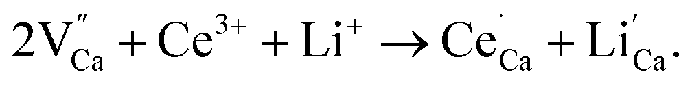 From Fig. 1, we can see the Ca2+ sites in the lattice are substituted by the doped ions without causing any impurity.


 , leading to the crossing of the 5d and 4f energy curves.42 At low temperature, the excited electrons will go back to ground state with light emission after dissipation some energy through phonon relaxation and the crystal will also returns to its original ground state geometry. However, at high temperature the excited electrons can absorb the phonon energy and be thermally activated to the crossing point. Finally, the electrons at crossing point decay nonradiatively to the ground state, making the thermal quenching appear. This phenomenon will be more severe with temperature increasing. Energy difference between point e and c is called activation energy (ΔE) which affects the thermal stability of phosphors directly. The value of ΔE can be determined by the following modify Arrhenius equation:43