
 Open Access Article
 This Open Access Article is licensed under a Creative Commons Attribution-Non Commercial 3.0 Unported Licence
High piezoelectric response and polymorphic phase region in the lead-free piezoelectric BaTiO3–CaTiO3–BaSnO3 ternary system
Wanwisa Janbuaac,
Theerachai Bongkarnb,
Taras Kolodiazhnyid and
Naratip Vittayakorn *ace
*ace
aElectroceramic Research Laboratory, College of Nanotechnology, King Mongkut's Institute of Technology Ladkrabang, Bangkok 10520, Thailand
bDepartment of Physics, Research Center for Academic Excellence in Applied Physics, Faculty of Science, Naresuan University, Phitsanulok 65000, Thailand
cAdvanced Materials Research Unit, Department of Chemistry, Faculty of Science, King Mongkut's Institute of Technology Ladkrabang, Bangkok 10520, Thailand. E-mail: naratip.vi@kmitl.ac.th; naratipcmu@yahoo.com
dNational Institute for Materials Science (NIMS), 1-1 Namiki, Tsukuba, Ibaraki 305-0044, Japan
eNano-KMITL Center of Excellence on Nanoelectronic Devices, King Mongkut's Institute of Technology Ladkrabang, Bangkok, 10520, Thailand
First published on 12th June 2017
Abstract
This study attempted to replace Pb-based piezoelectric ceramics with a non-toxic lead-free (Ba,Ca)(Ti,Sn)O3 substitute, according to current environmental standards. The design of the (Ba(0.825+x)Ca(0.175−x))(Ti(1−x)Snx)O3 lead-free piezoceramics reported herein was based on chemical modifications by varying Sn concentrations (x = 0.0500–0.1250). The effect of Sn ion modifications on structural evolution and dielectric, ferroelectric and piezoelectric properties was investigated. Partial substitution of Ti with Sn yields a suitable composition with multiphase boundaries near room temperature. As a result, the composition, x = 0.1000, shows outstanding piezoelectric values of d33 = 515 pC N−1 and  = 1293 pm V−1 at 10 kV, which are higher than those found in commercially available soft PZT. Furthermore, anomalous dielectric relaxation is far below the rhombohedral to orthorhombic phase transition at T ≈ 90–150 K, and was found clearly in all compositions. The relaxation fitted the Vogel–Fulcher model with an activation energy of Ea ≈ 20–70 meV and freezing temperature of TVF ≈ 65–85 K.
Introduction
Lead-based perovskite piezoceramics are suitable for universal actuators, sensors and transducers in many electromechanical devices, due to their superiority in both the piezoelectric coefficient (d33) and converse piezoelectric coefficient , as determined by a strain induced electric field.1 Despite their very useful properties, the impact of lead-containing ceramics on the environment has caused global concern. As a result, three groups of lead-free piezoelectric materials have been developed to replace commercial Pb-based materials completely. These groups include BaTiO3-, (K,Na)NbO3- and (Bi,Na)TiO3-based ceramics.2 The figure of merit (FOM) for the piezoelectric actuator is determined by the piezoelectric
  coefficient, with its value defined as the Smax/Emax ratio, where S is the induced strain and E the electric field applied. Therefore, it is important to achieve a high strain under minimal electric field.2–4 Piezoelectric properties of commercial lead-based materials usually demonstrate d33 = 400 pC N−1 and
  = 600 pm V−1 for sensor and actuator modes, respectively.4,5
A high strain response in (Bi,Na)TiO3-based systems was reported, with  values of about 300–720 pm V−1.6,7 Tan et al.8 recently reported a giant electrostrain of ∼0.70%, with
  = 1400 pm V−1 in non-textured (Bi,Na)TiO3-based ceramics. The outstanding electric field induced strain value in the (Bi,Na)TiO3-based ceramics displayed a large S–E hysteresis loop at a high electrical field (>40 kV cm−1). Higher d33 and
  values also were obtained in (K,Na)NbO3-based ceramics.9,10 Nevertheless, it is difficult to prepare dense ceramics by using ordinary sintering conditions and also implementing methods such as sintering aids.11,12 Therefore, numerous binary and ternary BaTiO3 or simple BT-based systems have been more attractive because of their excellent d33 and
  values, which are greater than those in the two former systems.13,14 Thus, the BT-based system was suggested as a potential choice for replacing Pb-based piezoelectric materials in some applications. It is well known that compositional design based on chemical modifications is the basic approach for enhancing piezoelectric properties. Cation substitution in the perovskite structure (ABO3) can be performed at the A- or B-sites and can induce either the morphotropic phase boundary (MPB), which is similar to the MPB behavior of Pb-based piezoelectric materials,1,2 or a polymorphic phase transition (PPT), where several structural phases of slightly different chemical compositions can coexist with each other near the ferroelectric–ferroelectric or ferroelectric–paraelectric phase transition temperature. The large d33 value of 697 pC N−1 and dielectric permittivity value of around 75
![[thin space (1/6-em)]](https://www.rsc.org/images/entities/char_2009.gif) 000 were reported in binary BaTiO3–xBaSnO3 ceramics by Y. Yao et al.,15 who showed coexistence of quasi-quadruple phases such as the cubic–tetragonal–orthorhombic–rhombohedral (C–T–O–R) phase.
000 were reported in binary BaTiO3–xBaSnO3 ceramics by Y. Yao et al.,15 who showed coexistence of quasi-quadruple phases such as the cubic–tetragonal–orthorhombic–rhombohedral (C–T–O–R) phase.
In general, single phase BaTiO3 exhibits a tetragonal (T) structure at room temperature (∼298 K). The rhombohedral to orthorhombic (R–O) and orthorhombic to tetragonal (O–T) phase transitions occur at ∼183 K and ∼273 K, respectively. The TR–O and TO–T of ceramic shift to a higher temperature by doping Sn4+ ion in the Ti4+ site of the BaTi1−xSnxO3 system, while the Curie temperature (Tc) decreases.1,15,16 On the other hand, doping Ca2+ ion in the Ba2+ site of Ba1−xCaxTiO3 ceramic tends to lower the TO–T transition temperature, but only affects the Tc temperature slightly, which helps to keep the latter stable for actual piezoelectric application.1 Furthermore, both Ca2+ and Sn4+ ions were doped in Ba- and Ti-sites of the BT structure in order to bring the TR–O and TO–T close to room temperature and also create a multiphase compound. Li et al.17 reported high piezoelectric properties with d33 = 510 pC N−1 and electromechanical coupling coefficient (kp) = 48% in (Ba1−xCax)(Ti0.96Sn0.04)O3, which resulted from the compound being close to the PPT boundary comprising the O–T phases. They18 also reported the effect of Ca content on the piezoelectric properties of (Ba1−xCax)(Ti0.94Sn0.06)O3 ceramics. Later, Zhu et al.19 showed that the (Ba1−xCax)(Ti0.92Sn0.08)O3 system exhibited d33 up to 568 pC N−1, kp = 47.7%, and  = 1013 pm V−1 near room temperature at the O–T boundary. Furthermore, efforts to form a mixed phase by compositional modifications were attempted in (1 − x)Ba(Sn0.12Ti0.88)O3–x(Ba0.7Ca0.3)TiO3,20, (Ba0.95Ca0.05)(Ti1−xSnx)O321 and (Ba0.90Ca0.10)(Ti1−xSnx)O322 ceramics, where the R–T, R–O–T and O–T phase boundaries were found, respectively, resulting in the enhancement of piezoelectric properties. Based on the literature,17–22 the structural pseudo-ternary diagram of the BaTiO3–CaTiO3–BaSnO3 (BT–CT–BS) system is shown in Fig. 1. This study focused on the (Ba(0.825+x)Ca(0.175−x))(Ti(1−x)Snx)O3 (BT–CT–xBS) compositions, which traverse the multiphase region, as shown by the “◇” symbols in Fig. 1. A suitable composition may display multiphase coexistence at room temperature, in which case a high piezoelectric response is expected, based on the MPB or PPT concept.
 | ||
| Fig. 1 Ternary diagram of BaTiO3–CaTiO3–BaSnO3 ceramics. | ||
This study explored the polymorphic phase region of (Ba0.825+xCa0.175−x)(Ti1−xSnx)O3 ceramic, with the compositions, x = 0.0500, 0.0625, 0.0750, 0.0875, 0.1000, 0.1125 and 0.1250, being fabricated via the conventional solid-state reaction method. Phase transformations and coexistent phases resulted from chemical modifications of the Sn ion at the B-site, and the relationship between the compositions and piezoelectric properties was discussed.
Experimental
The (Ba0.825+xCa0.175−x)(Ti1−xSnx)O3 ceramics with the compositions, x = 0.0500–0.1250, were prepared by the conventional solid-state reaction method, with metal oxides and carbonates. Dried BaCO3 (≥98.5%, Sigma-Aldrich), CaCO3 (≥98.5%, Riedel-de Haen), TiO2 (99.9%, Sigma-Aldrich), and SnO2 (99.9%, Sigma-Aldrich) powders were weighed in accordance with the stoichiometric ratio. All mixed powders were milled with yttria-stabilized zirconia balls for four hours by high-energy vibration milling, and ethanol was used as an intermediary before drying in an oven at 85 °C for 24 h. Next, the mixed powders were calcined at 1200 °C for 4 h (heating/cooling rate of 5 °C min−1). The calcined powders were sieved for uniform particle size and mixed with 5% polyvinyl alcohol (PVA). Circular disks of 10 mm diameter were pressed uniaxially with 2 tons weight for 2 min, and sintered at 1450 °C for 2 h in air (heating/cooling rate of 5 °C min−1). The density of the samples was examined using Archimedes' principle for the desired relative density of over 95%.An X-ray diffractometer (Bruker-AXS D 8 Advance) was used to determine the structure of powders obtained after the sintered pellets had been ground using Cu Kα1 radiation, and data were collected in the 2θ range from 20° to 70° with a step size (2θ) of 0.02, together with a time per step of 1 s. The sintered samples were polished until they had reached the required smooth surface before the Raman measurement was taken. A Raman spectrophotometer (Dispersive Raman Microscope, SENTERRA, Bruker) was used to support the XRD data, by using the 532 nm exciting line of a He–Ne laser, with recorded wavelength in the range of 50 to 1000 cm−1 at room temperature.
The ceramic samples were prepared for electrical measurement by polishing both sides of the pellets to a smooth surface, using 600, 1000 and then 2000 series number of grinding paper. The samples were polished down to about 1 mm thickness for dielectric measurement, and <0.7 mm thickness for ferroelectric and piezoelectric measurement. Ag paste electrodes (Heraeus, C1000) were applied and then fired at 750 °C for 30 min. Dielectric characterization was performed using an Alpha Impedance Analyzer (Novocontrol, Germany) in conjunction with the physical property measurement system (PPMS, Quantum Design, USA), at a frequency of 10–10000 Hz and temperature range from 2 K to 360 K, to determine the phase transition temperature. The ferroelectric hysteresis loop was measured by using a ferroelectric tester system (RT66B; Radiant Technologies, Inc., Albuquerque, NM), based on the Sawyer–Tower circuit, with Vision software and high voltage amplifier (Trek) in silicone oil at room temperature, and a frequency of 4 kHz. The unipolar and bipolar strain characteristics were measured for converse piezoelectric measurement, using the MTI-2100 photonic sensor with fiber-optic probes (high-resolution module resolved to 0.01 μin, 2.5 angstroms), in conjunction with the ferroelectric tester system in silicone oil at room temperature. The  or converse piezoelectric coefficient was calculated from the relationship of maximum strain divided by the maximum electric field (Smax/Emax). The ceramic samples were poled in silicone oil under a DC electric field of 30 kV cm−1 for 30 min at room temperature before the direct piezoelectric coefficient (d33) was examined. The d33 coefficient was measured using a Berlincourt d33 meter (YE2730A, APC International Ltd., USA).
Results and discussion
Fig. 2(a) illustrates the XRD patterns of BT–CT–xBS (x = 0.0500–0.1250) ceramics at room temperature, which closely match the JCPDS diffraction peaks of pure BaTiO3, as shown by vertical black lines on the plane. JCPDS numbers 05-0626, 81-2200, 85-0368, and 31-0174 belong to tetragonal (T), orthorhombic (O), rhombohedral (R) and cubic (C) symmetry, respectively. All of the samples exhibited a perovskite structure, and no secondary or impure phases were detected. This result indicates that a solid solution was achieved by Ca2+ and Sn4+ diffusion at the A- and B-sites of the perovskite structure, respectively. An expanded view of the peaks at 2θ = 38.5–39.5°, 44–46.5°, and 55.5–57° is shown in Fig. 2(b). Diffraction peaks for the composition, x = 0.0500, exhibited tetragonal symmetry, with splitting between the (002) and (200) peaks at 2θ ≈ 45°. The peak intensity of (200) and (211) was slightly higher than that of (002) and (112), respectively, as observed at 2θ ≈ 56°. The crystal structure at the composition, x = 0.0625, continued to exhibit T-symmetry, with peak splitting and intensity similar to that of the composition, x = 0.0500. By increasing the Sn content, the expanded diffraction peaks became broader gradually for the compositions, x = 0.0750–0.1000, at 2θ ≈ 45° and 56°. Eventually, the peaks were seen to merge into a single one at the compositions, x = 0.1125–0.1250, as observed at 2θ ≈ 39°, 45°, and 56°. Each enlarged diffraction peak did not match the T- and O-symmetry exactly at the compositions, x = 0.1125–0.1250, but rather matched the R- or C-symmetry, due to no splitting at 2θ ≈ 45° and possibly because of its mixture. The structural phase transition of BT–CT–xBS ceramics may change from T- to R- or C-symmetry. The compositions of the phase transition regions were in the range of x = 0.0750–0.1000. Furthermore, the diffraction peaks shifted to lower angles with increasing x content, indicating the replacement of Ti4+ (with an ionic radius of 0.605 Å); and Sn4+ had a larger ionic radius of 0.69 Å. The detected expansion of the unit cell was similar to the results observed by Singh et al. in Sn-doped BaTiO3.23 | ||
| Fig. 2 (a) XRD patterns of BT–CT–xBS ceramics with the compositions, x = 0.0500–0.1250, and (b) the expanded peak at 2θ of around 38.5–39.5°, 44–46.5°, and 55.5–57°. | ||
It is known that XRD data provide mainly global macroscopic symmetry of ceramics; the local structure of small cluster regions of different ferroelectric phases may not be evidenced clearly. In contrast, Raman spectroscopy is an informative technique that characterizes lattice dynamics and local structure, and was used to examine local structural distortions and low symmetry ferroelectric phases in many lead-free piezoelectric systems.24–26 It was used in conjunction with the XRD results of this study to support the presence of different local structures and ferroelectric phase transitions as a function of composition in the ceramics.
Fig. 3(a)–(c) show room temperature Raman spectra of BT–CT–xBS ceramics, with the compositions, x = 0.0500–0.1250, measured in a frequency range of 50–1000 cm−1. There are five atoms inside the unit cell of a perovskite structure, which has 12 optical vibrational modes. The optical modes in a cubic symmetry, with Pm3m space group, belong to 3F1u + F2u irreducible representations. The F1u modes give A1 and E modes, while the F2u modes provide B1 and E modes when transforming into the T-phase (P4mm). The A1 and E symbols are Raman-active phonon modes of the T- (C4v) phase, which split into transverse (TO) and longitudinal (LO) optical modes when an electrostatic force is induced. All Raman-active modes in Fig. 3 agree well with previous reports.25,26
 | ||
| Fig. 3 (a) Raman spectra of BT–CT–xBS ceramics with the compositions, x = 0.0500–0.1250, and (b) and (c) the expanded peak at around 100–300 and 200–400 cm−1. | ||
The characteristic peaks of a perovskite ferroelectric phase can be observed in all compositions that consist of a sharp peak at around 296 cm−1, and broad peaks at around 520 cm−1 and 724 cm−1, which correspond to the E(TO2), A1(TO3)/E(TO) and A1(LO3)/E(LO3) modes, respectively. Furthermore, an interfering effect between a narrow and broad A1(TO) mode presents a dip at around 176 cm−1, which is attributed to a ferroelectric phase. It is known that Ca2+ ion can be substituted in either an A- or B-site of the perovskite BT structure. The Ca solubility can reach up to x = 0.04 for B-site substitution in BaTi1−xCaxO3.27 Pokorný et al.28 recently reported an A1g peak mode at ∼800 cm−1 that associated with the mixed Ti4+ and Ca2+ occupancy of the B-site. In this study, the A1g peak is absent in the Raman data, which confirms that the Ca2+ ion prefers to diffuse into an A-site of the perovskite structure in (Ba0.825+xCa0.175−x)(Ti1−xSnx)O3 compositions.
The compositions, x = 0.0500–0.0625, show the characteristics of a T-phase due to a broad peak at around 270 cm−1, which corresponds to the A1(TO2) mode and a minute peak of the A1(LO2)/E(LO) mode at around 469 cm−1.26,28 This result is consistent with the XRD patterns observed for the compositions, x = 0.0500–0.0625. Although the main feature of the Raman spectra is consistent with the T-phase for the compositions, x = 0.0500–0.0625, there are changes seen in the range of 100–300 cm−1. These are associated with the polar BO6 vibrations that are characteristic of the O- and R-phases, as Sn content increases in the compositions, x = 0.0750–0.1250. Study of the temperature dependent Raman spectra of pure BaTiO3 indicates that the peak mode near 191 cm−1 only exists in the O- or R-phase and not in the T- and C-phase.25,29 The A1(TO1) mode near 191 cm−1 has been reported as a characteristic of the O-phase,30 which starts to emerge in the composition, x = 0.0500 until x = 0.1250, as shown in Fig. 3(b). Three peaks that present at frequencies of 106, 155 and 191 cm−1 correspond to E(TO1), A1(LO) and A1(TO1) modes, respectively, which is characteristic of the R-phase.26,30 Nevertheless, quantity of the R- or O-phase in this study is not significant in the ceramics.
The asymmetric band was made to fit at 160–300 cm−1 by peak de-convolution with a Gaussian function (R2 ≥ 0.97). Fig. 4(a)–(d) show fitted peaks for the composition, x = 0.0500, x = 0.0750, x = 0.1000, and x = 0.1250, respectively. The peak number 1 is located at around 191 cm−1, which corresponds to the A1(TO1) mode observed in only the O- or R-phase. Peak number 2 and 3 are around 232 and 260 cm−1, respectively, which corresponds to the A1(TO2) mode. Perry et al. reported that the A1(TO2) mode is present near 230 cm−1 in the O-phase and transforms to 267 cm−1 in the T-phase.31 The emergence of both A1(TO2) modes also was reported in Ba1−xCax(Zr0.05Ti0.95)O3 ceramics, with a crossover from the O- to T-phase.32 The intensity and area under the curve of de-convoluted peak number 1 tend to increase, whereas peak number 3 tends to decrease, indicating that the R-phase develops and the T-phase is lost. This corresponds to the variable intensities of the E(TO1) peak, suggesting that the volume fraction of the R-phase increases as the peak becomes sharper with increasing Sn content [in Fig. 3(b)]. It is interesting that the Raman spectra in Fig. 4(a)–(d) clearly show the presence of T-, O-, and R-phases in all compositions. It can be concluded, based on the XRD and Raman results, that the global structure of x = 0.0500–0.1000 ceramics exhibits a T-phase based mainly on XRD data, while the O- and R-phase are present in some local areas of the global T-phase structure, which is supported by the Raman results.
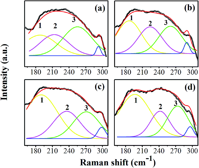 | ||
| Fig. 4 The peak de-convolution at 160–300 cm−1 of the compositions, x = 0.0500 (a), x = 0.0750 (b), x = 0.1000 (c), and x = 0.1250 (d), respectively. | ||
More evidence of local nano-clusters is seen clearly in the presence of the E(TO1) peak at 106 cm−1 in the Raman data. The E(TO1) peak is related to Sn–O motion in the perovskite structure and regarded as an indicator of the presence of the nanometer-sized Sn-rich perovskite phase.33 The presence of the E(TO1) peak is possible at 106 cm−1 only if Sn-rich domains extend over tens of unit cells, in order that the phonon can give rise to a definite Raman peak. The existence of Sn-rich clusters in the Ba(Ti1−xSnx)O3 also was confirmed clearly by the synchrotron X-ray Absorption Near-Edge Structure (XANES) results, even though splitting peaks in the XRD patterns were not observed.34 In addition, the peak intensity of the E(TO2) and A1(LO3)/E(LO3) modes decreases explicitly, and the dip at around 176 cm−1 between the A1(LO) and A1(TO1) mode gradually vanishes with increasing Sn composition of up to x = 0.1250, as shown in Fig. 3(a)–(c). These results indicated that the relative volume of the ferroelectric phase decreases, due to the appearance of the paraelectric phase in some local areas. The characteristic of the pure cubic phase is supported by two broad bands at around 250 cm−1 and 520 cm−1.30 It also corresponded with broader and higher peak intensity of around 250 cm−1 at the compositions, x = 0.1125–0.1250. Thus, the C-phase is mixed possibly with the compositions, x = 0.1125–0.1250, which correspond with the dielectric data presented below, in that increasing Sn composition shifts the Tc temperature close to room temperature for the last two compositions. The Raman findings, based on the combined results of this study, agree well with the XRD data that clarify the crystal structure of the samples.
Fig. 5(a)–(g) illustrate temperature dependence of relative permittivity (εr) and dielectric loss (tanδ) of BT–CT–xBS ceramics by specifying the acronyms and color bars for different phase transitions. The three pronounced tanδ peaks in the compositions, x = 0.0500–0.1000, are associated with the three ferroelectric phase transitions: R–O at the temperature of (TR–O) ≈ 200–250 K, O–T at the temperature of (TO–T) ≈ 250–300 K and T–C at the temperature of (TT–C) ≈ 300–350 K. The ferroelectric phase transitions show a significant change of compositions. As expected, the R–O and O–T phase transitions were shifted close to room temperature, while the TT–C or Tc decreased slightly with Sn substitution. The TR–O, TO–T and Tc are evidenced clearly near room temperature at the composition, x = 0.1000, which is seen clearly in Fig. 5(h), where ∂εr/∂T is plotted for the composition, x = 0.1000. As x increases to over 0.1000, the three phase transition peaks merge into one broad peak at Tc for the composition, x = 0.1125. The R–O and O–T phase transitions disappear gradually at the composition, x ≥ 0.1125 [Fig. 5(i)], which implies that the O–R–T phase convergence is located in the composition range of x = 0.1000 and 0.1125. Finally, there is only one εr peak left that corresponds to the R–C phase transition at Tc and the R-phase appears in the composition, x ≥ 0.1125.
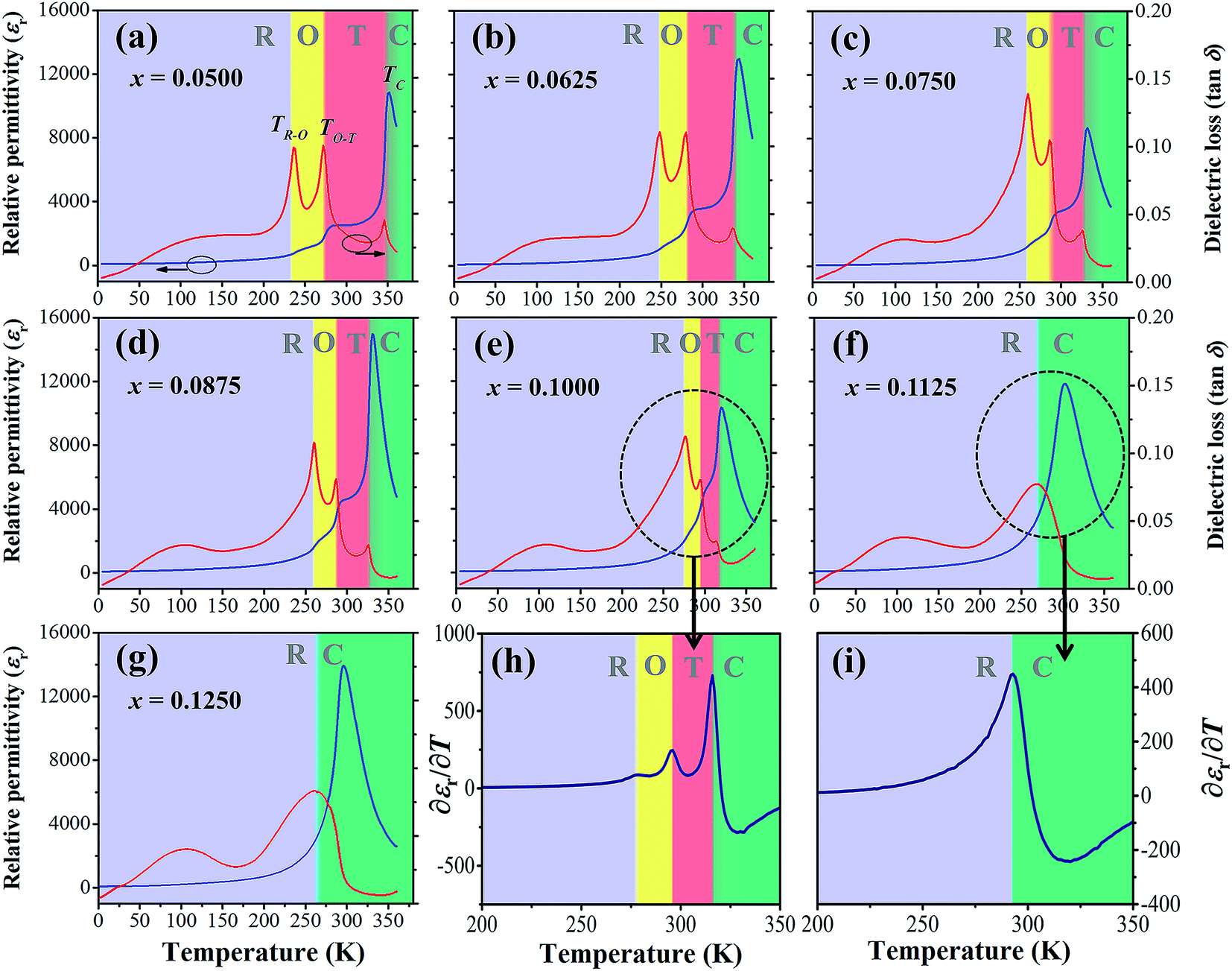 | ||
| Fig. 5 Dielectric permittivity and dielectric loss versus temperature curves of BT–CT–xBS ceramics; x = 0.0500–0.1250 (a)–(g) in the range of 2–360 K at 1 kHz; derivative of the dielectric permittivity versus temperature (∂εr/∂T) for the compositions, x = 0.1000 (h) and 0.1250 (i). | ||
The Tc peak shifts to a lower temperature and broadens gradually with increasing Sn content. This result shows similar behavior to Sn-substituted BaTiO3-based ceramics, as reported in the literature.22,23 By substituting Ti4+ with Sn4+, non-ferroelectric SnO6 octahedra enter the matrix of the ferroelectric phase. The non-ferroelectric regions disrupt the long-range order of the TiO6 ferroelectric octahedra, causing unstable off-center displacements of Sn atoms and oxygen ligands, which lead to lowering Tc. Also, the local Tc values may vary, due to the random distribution of Sn in the samples, leading to a broad dielectric peak with diffuse phase transition.35
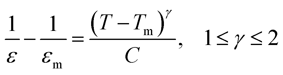
According to the modified Curie–Weiss law, diffuse phase transition follows an empirical εr relationship with temperature:36
 | (1) |
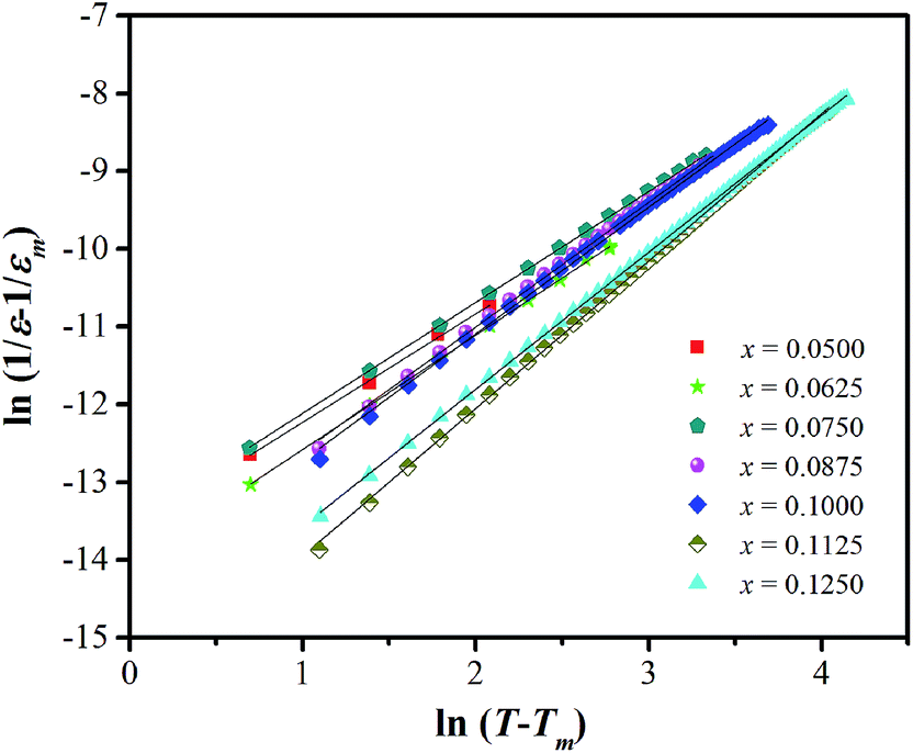 | ||
| Fig. 6 ln(1/ε − 1/εm) versus ln(T − Tm) at 1 kHz for BT–CT–xBS ceramics. | ||
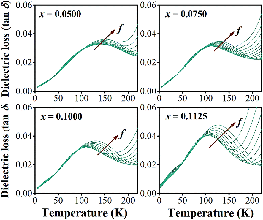
In addition to the three ferroelectric phase transitions, dielectric data in this study show a broad tanδ peak at 100–160 K in all compositions. At the same time, the dielectric permittivity increases gradually from ∼90 to ∼700 in T = 2–180 K, with a small broad kink at ∼125 K, as shown in Fig. 7. In addition, a small low-temperature shoulder peak in tanδ was found in the compositions, x = 0.1125–0.1250. Fig. 8 shows the temperature dependence of tanδ at various frequencies for the compositions, x = 0.0500, x = 0.0750, x = 0.1000, and x = 0.1250, respectively, which demonstrates the tanδ peak shifting towards higher temperatures with increasing frequency. In general, this dependence is characteristic of either a simple Arrhenius-type thermally-activated process:
 | (2) |
 | (3) |
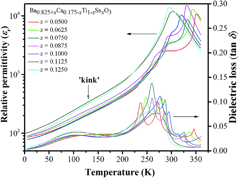 | ||
| Fig. 7 Temperature dependence of dielectric permittivity and loss tangent measured at 10 Hz for BT–CT–xBS ceramics. A small ‘kink’ in dielectric permittivity at T ∼ 125 K is marked by a vertical arrow. | ||
 | ||
| Fig. 8 tanδ with varying frequency at a temperature in the range of 2–200 K for BT–CT–xBS ceramics. | ||
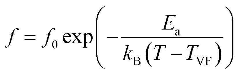
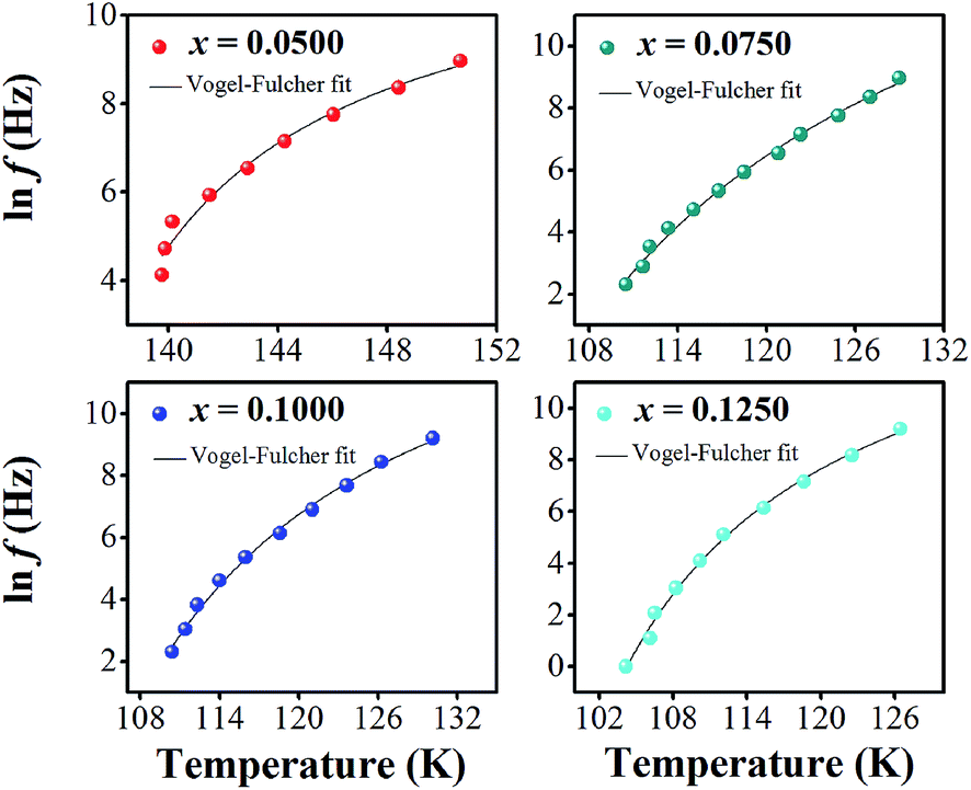
In eqn (2) and (3), f is the applied frequency, f0 the attempted frequency of dipolar reorientation, Ea the energy barrier of the reorientation process, T the maximum temperature of the tanδ peak at an applied frequency, TVF the ‘static’ dipolar freezing temperature and kB the Boltzmann constant. An attempt to fit the data with eqn (2) produced reasonable activation energies of Ea in the range of 330–625 meV, but unphysical attempts at high frequency f0 at 1019–1024 Hz, were well beyond optical phonons. Results of the fit with the Vogel–Fulcher model of eqn (3) are shown in Fig. 9 for the compositions, x = 0.0500, x = 0.0750, x = 0.1000, and x = 0.1250, respectively. The fitting parameters are listed in Table 1. A good quality fit with physically sound parameters was obtained for the compositions, x = 0.0750–0.1250, with Ea ranging from 27 to 71 meV, f0 = 107–1010 Hz and TVF = 65–86 K. The poor fit for the compositions, x = 0.05–0.0625, was attributed to a poorly-resolved tanδ peak, probably resulting from several partially overlapping peaks in the T = 50–150 K range. Indeed, Fig. 8 shows that the main tanδ peak at T = 100 K, as well as the low-T shoulder at 30 K, becomes resolved more clearly with increased Sn substituting x.
 | ||
| Fig. 9 Natural logarithm of frequency [ln(f)] versus 1/T of BT–CT–xBS ceramics. | ||
| Composition | lnf0 (Hz) |
f0 (Hz) | TVF (K) | Ea (meV) | χ2 |
|---|---|---|---|---|---|
| x = 0.0500 | 12.21 ± 1.44 | 2.01 × 10⁵ ± 4 | 131.27 ± 2.77 | 5.6 ± 3.0 | 0.07043 |
| x = 0.0625 | 9.54 ± 0.58 | 1.39 × 10⁴ ± 2 | 123.14 ± 0.87 | 2.2 ± 0.7 | 0.10293 |
| x = 0.0750 | 19.14 ± 2.27 | 2.06 × 10⁸ ± 10 | 80.46 ± 6.21 | 43.2 ± 14.7 | 0.02408 |
| x = 0.0875 | 23.34 ± 2.01 | 1.37 × 10¹⁰ ± 7 | 65.42 ± 5.30 | 70.6 ± 16.3 | 0.00807 |
| x = 0.1000 | 16.54 ± 1.43 | 1.53 × 10⁷ ± 4 | 88.38 ± 3.80 | 26.7 ± 7.3 | 0.02479 |
| x = 0.1125 | 16.49 ± 1.60 | 1.46 × 10⁷ ± 5 | 83.89 ± 4.75 | 30.0 ± 9.1 | 0.03163 |
| x = 0.1250 | 16.63 ± 1.31 | 1.66 × 10⁷ ± 4 | 85.79 ± 2.79 | 26.4 ± 6.0 | 0.04949 |
It is not inconsequential to identify the source of low-temperature dielectric relaxation explicitly. Both defects and domain walls can cause Vogel–Fulcher relaxation similar to that reported here. Low-frequency (i.e., f0 = 105–107 Hz) relaxation is assigned usually to the domain wall motion,37 whereas high frequency (i.e., f0 = 108–1012 Hz) relaxation is attributed to defect-induced dipolar relaxation.38 Attempted relaxation at even higher frequency (f0 = 1014–1016 Hz) may originate in perovskites from small polaron effects.39 Coupling between the dominant domain-wall and defect-dominant relaxation mechanisms was discussed in ref. 40.
For example, pronounced VF relaxation with Ea = 72 meV, f0 = 1012 Hz and TVF = 90 K was reported for the BaTiO3–0.3BaSnO3 nonergodic relaxor.16 The energy scale of this relaxation is similar to that found in this work, but the attempted frequency differs by 2–4 orders of magnitude. Existence of the FE state with the domain walls is not a necessary requirement for dielectric relaxation. In fact, defect relaxation in non-ferroelectric perovskites has been well documented in the literature. For example, relaxation of the Li impurity ion in KTaO3 has characteristic parameters of Ea = 86 meV and f0 = 8 × 10¹² Hz;41 Mn defect on the Sr site in SrTiO3 relaxes at f0 = 1012–1013 Hz with Ea = 64–78 meV.42 In non-stoichiometric BaMg1/3Ta2/3O3, Mg ion misplaced at the Ba site relaxes at f0 = 109 Hz with Ea = 38 meV, whereas oxygen vacancy relaxation occurs at f0 = 5 × 10¹² Hz and Ea = 360 meV.43 Other reports on the relaxation of oxygen vacancy in perovskites44–50 show strong composition dependence of activation energy in the range of 350–910 meV. In view of the literature data discussed, it seems unlikely that the low-temperature relaxation reported here is associated with oxygen vacancy relaxation. It is most plausible that the low-temperature relaxation in the samples of this study is attributed to either defects of impurity or Sn4+ and Sn2+ ions misplaced at the A-site because of the rather slow relaxation dynamics (Table 1).
The ferroelectric phase diagram was established according to the dielectric results, as displayed in Fig. 10(a). The diagram consists of three ferroelectric phases; R-, O-, and T-phase and one cubic paraelectric phase. Tc decreases linearly as the Sn content increases at the rate of 765 K mol−1 and TR–O and TO–T shift close to room temperature for the composition, x = 0.1000. As a result, ceramics with the composition, 0.1000 < x < 0.1125, are expected to exhibit the O–R–T phase boundary. Fig. 10(b) shows a contour plot of εr, as a function of temperature and composition related to the phase diagram for BT–CT–xBS ceramics. The maximum εr values are found typically in the neighborhood of the Tc line, as shown by the yellow-red boundary. Maximum εr is located at 327 K for the composition, x = 0.0875. It is well known that dielectric and ferroelectric properties contribute to the variation of piezoelectric properties such as d33 ∼ εrPr,51,52 which has been used to describe the role of identifying direct piezoelectric properties in several KNN-based piezoceramics. In particular, most piezoelectric materials usually operate at room temperature. Thus, TR–O and TO–T are important factors that lead to commanding properties. As the phase transition temperatures (TR–O, TO–T, and Tc) shift close to room temperature for the compositions, x = 0.1000–0.1250, the room-temperature value of εr is enhanced significantly. Even though the highest composition, x = 0.1250, is in the orange area (εr ∼ 13500) at room temperature, it has a cubic phase and is, therefore, not expected to show outstanding piezoelectric properties. It is interesting that the compositions, x = 0.1000–0.1125, are inferior to the composition, x = 0.1250, in terms of εr, but they are expected to show outstanding piezoelectric behavior because of their multiphase composition. However, the composition, x = 0.1000, could possibly achieve the highest piezoelectric properties because the composition, x = 0.1125, is located too close to the cubic (paraelectric) phase. In comparison, the relative permittivity value of the composition, x = 0.1000 (εr ∼ 5580), is higher at room temperature than that of soft PZT (εr ∼ 2000–3500) and other BT-based (εr ∼ 3060) ceramics.13 This is in accordance with a report by Shi et al.35 in that Sn doping causes enhancement of dielectric permittivity, due to the formation of polar nanoregions (PNRs) that are buried in the BT-based matrix.
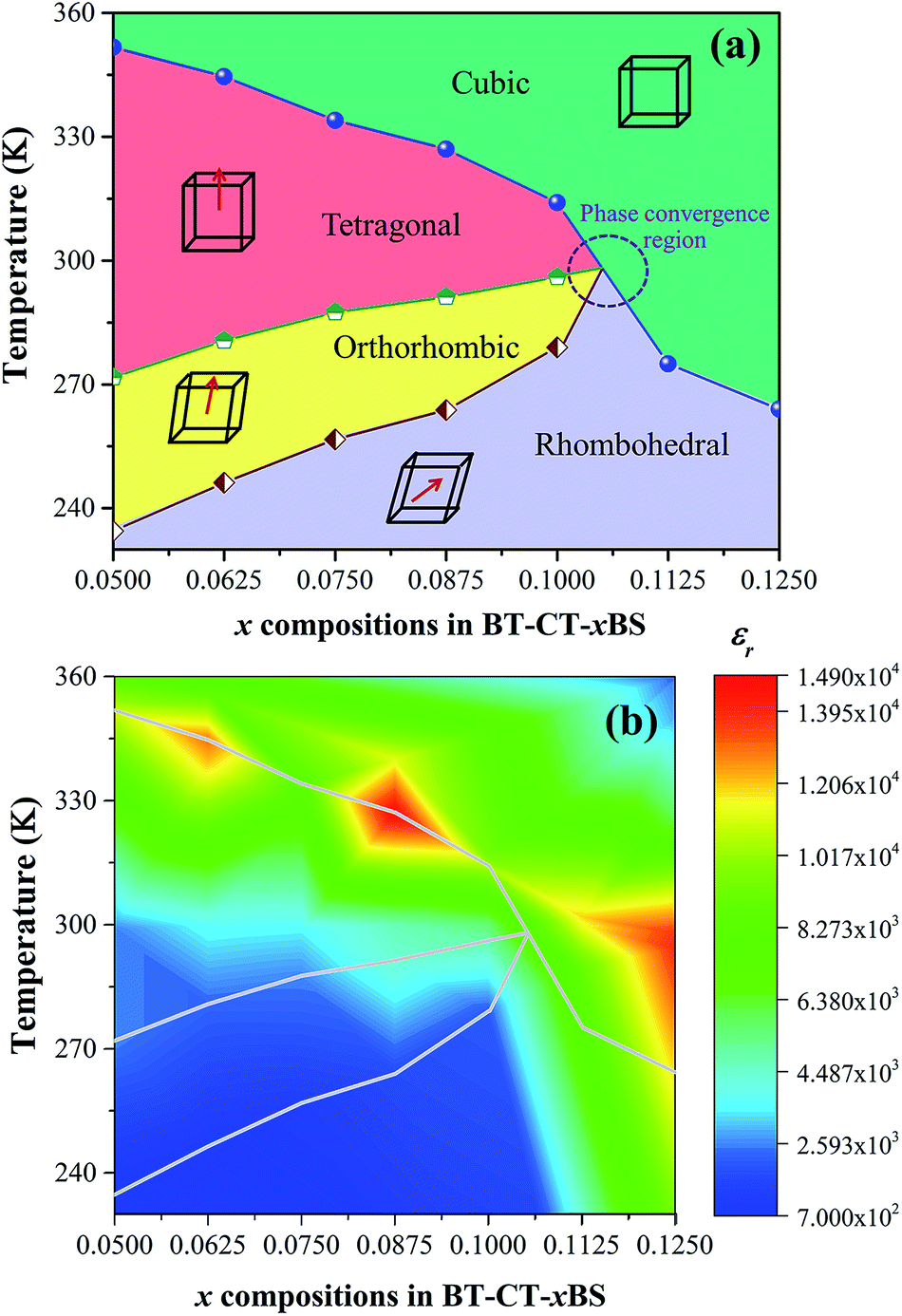 | ||
| Fig. 10 (a) Phase diagram of BT–CT–xBS ceramics, (b) contour plot of the dielectric constant with temperature and composition of BT–CT–xBS ceramics. | ||
In order to comprehend the preferable relationship between the constructed phase diagram and electromechanical properties, ferroelectric and piezoelectric properties were measured as a function of Sn compositions. Fig. 11(a) displays room-temperature polarization in an electric field of up to 50 kV cm−1, measured at a frequency = 4 Hz. It is seen clearly that all Sn-doped compositions produce a typical ferroelectric (FE) hysteresis loop with remnant polarization (Pr), saturated polarization (Ps) and coercive field (Ec). The Sn-composition dependence of Pr, Ps and Ec is shown in Fig. 11(b). The Ec value tends to decrease at higher x because it is easier to switch the non-180° domain wall in the R-phase, which is mixed with other phases at x = 0.1000–0.1250, as supported by the XRD, Raman, and dielectric results. This behavior is similar to that observed in other lead-free piezoceramics, which show lower Ec values in the R-phase.14,51 Also, the Pr and Ps values are likely to decrease with higher Sn concentration. It is evident that Pr and Ps values are varied by Sn-substituted compositions, which result from different structural phases. A change in the hysteresis behavior of the BT–CT–xBS ceramics is represented quantitatively by the FE loop squareness, Rsq, calculated from the following equation:53
 | (4) |
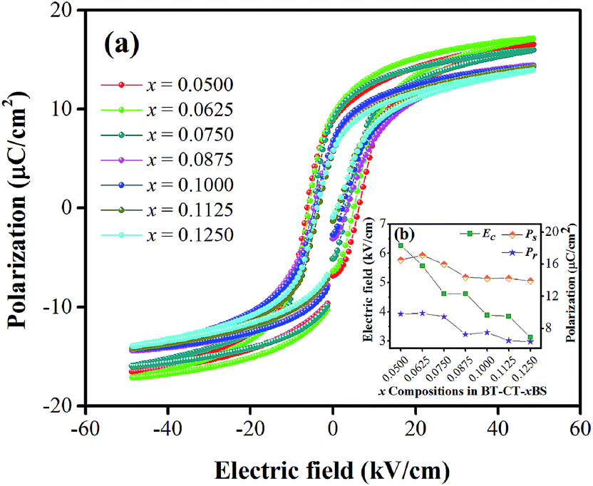 | ||
| Fig. 11 (a) Composition-dependent P–E hysteresis loops of BT–CT–xBS ceramics at room temperature, (b) Pr, Ps and Ec, with composition dependence. | ||
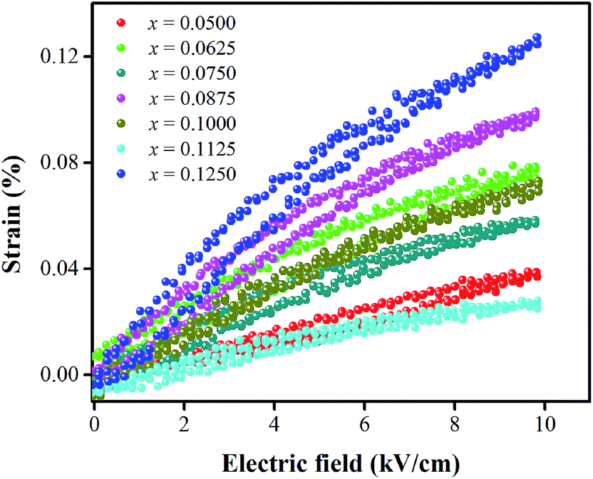
Strain induced by an electric field was measured to investigate the efficiency of BT–CT–xBS ceramics for actuator applications. Fig. 12 displays a unipolar strain versus E for BT–CT–xBS ceramics at room temperature, with the maximum E = 10 kV cm−1 applied. The strain increases gradually with x until it reaches the highest value of about 0.127% at x = 0.1000, before decreasing to 0.028% at x = 0.1250. The normalized strain value or converse piezoelectric coefficient  was calculated from the relationship of Smax/Emax in units of pm V−1. Fig. 13 shows the d33 and
  dependence of compositions in BT–CT–xBS ceramics. Similar tendencies are seen clearly in both d33 and
  values. The d33 and
  coefficients increase initially at the composition, x = 0.0625, with d33 = 385 pC N−1 and
  = 804 pm V−1 until maximum values of 515 pC N−1 and 1293 pm V−1 are reached at x = 0.1000. Eventually, both values drop to d33 = 104 pC N−1 and
  = 285 pm V−1 at x = 0.1250, due to the cubic phase that dominates the phase mixture. The highest d33 and
  value were observed clearly at the composition, x = 0.1000. The high piezoelectric response in the composition, x = 0.1000, is caused by its multiphase transition temperature located near room temperature. The TR–O, TO–T, and Tc are evident near room temperature.
 | ||
| Fig. 12 Unipolar strain with electric-field of BT–CT–xBS ceramics at room temperature. | ||
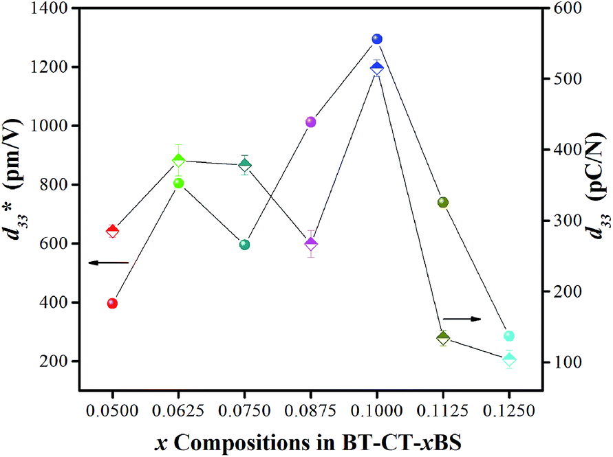 | ||
Fig. 13 Dependence of d33 and  values and x compositions in BT–CT–xBS ceramics. values and x compositions in BT–CT–xBS ceramics. | ||
It is well-known that the dynamic of multiphase transition has preferred oriented polarizations in more than 26 directions at the composition, x = 0.1000, (i.e., 6, 12 and 8 for the T-, O-, and R-phase, respectively), which confirms the dielectric result. The PPT and MPB region enhance ferroelectric and piezoelectric properties, due to the intrinsic (compositions, polarized rotation, and polarized elongation/compression) and extrinsic domain wall effect.54,55 Flattened free energy is caused by being near the Curie temperature, which affects the intrinsic effect.55 The compositional design based on chemical modifications creates a low Tc at the composition, x = 0.1000, which leads to an easy path for polarized rotation and extension at the multiphase boundary that acts on a unit cell scale. This contributes to intrinsic structural instabilities and improved piezoelectricity. Furthermore, the phase boundary makes it easier for domain wall motions56,57 because of structural instability near the Curie temperature. In particular, the non-180° domain wall motion of O- and R-phase54 induces piezoelectric properties that show a particularly high strain. As discussed previously in the dielectric result, the composition, x = 0.1000, exhibits TR–O and TO–T phase transition near room temperature. Hence, the electric field has an enormous impact on phase transitions more in this composition than in others. It was reported that polarized rotation from a [111] to [001] direction, induced by an external electric field, can drive the phase transition from R- to T-phase in the perovskite ferroelectrics, BaTiO3.58,59 Polarized rotation with flat free energy can motivate lattice-deformation, leading to a better piezoelectric response. Thus, large piezoelectric coefficients at the composition, x = 0.1000, are believed to ease polarization of the rotation by enough electric field during strain measurement, due to the nearest R–O–T multiphase transition.
The maximum values of d33 and  at the composition, x = 0.1000, in this study were compared to other lead-free piezoelectrics13,29,60–63 and commercially available soft PZT ceramics, as shown in Fig. 14. The values of d33 and
  are comparable to some BT-based ceramics. However, the best d33 and
  values are higher than those reported for commercially available soft PZT (d33 = 410 pC N−1 and
  = 600 pm V−1).4 This Ba0.925Ca0.075Ti0.9Sn0.1O3 piezoelectric material is devoid of Pb, which is attractive, non-toxic for the environment and follows current legislation. Its use is possible for replacing commercial lead-based piezoelectric ceramics in actuator applications.
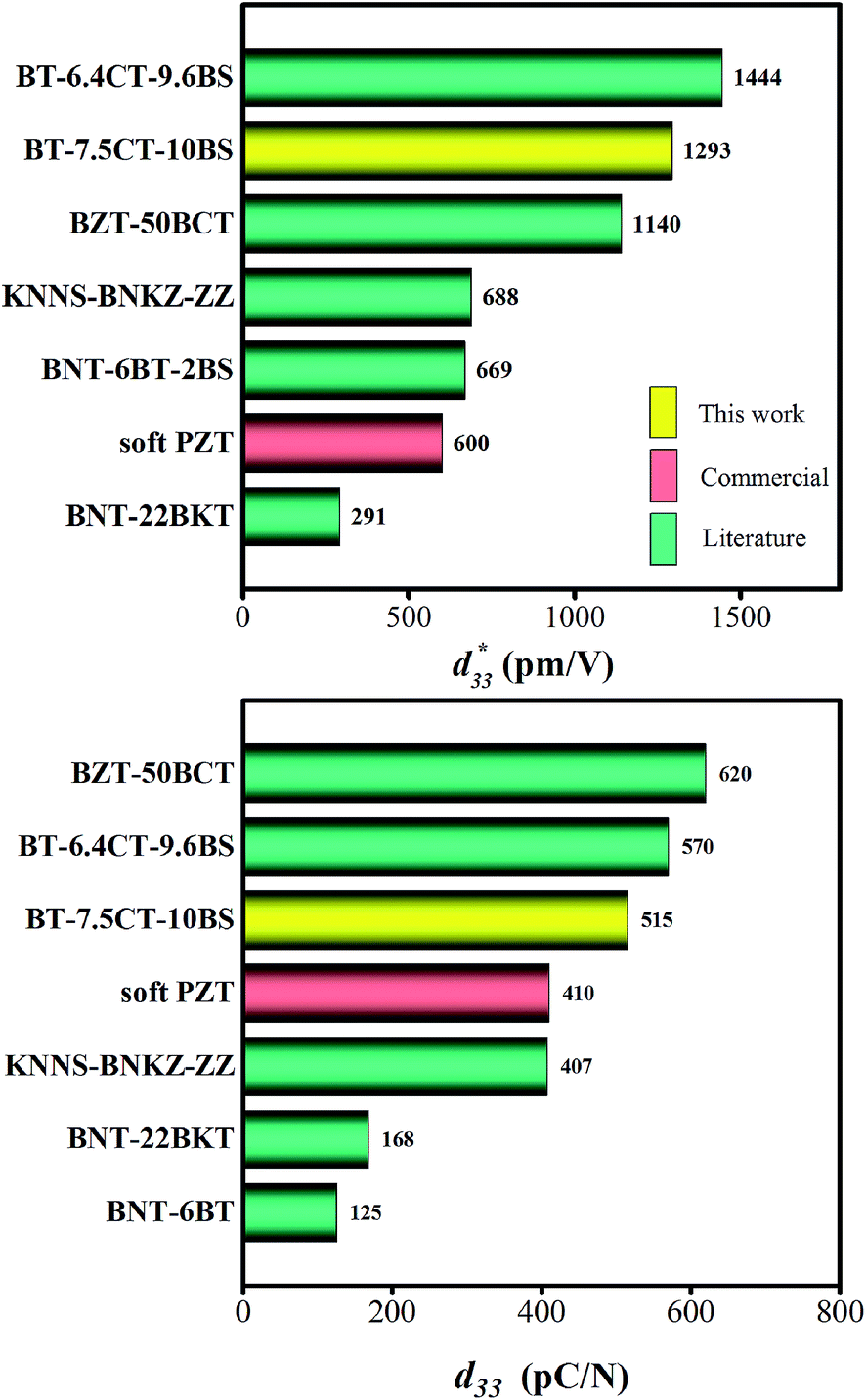 | ||
Fig. 14 Comparison of  (top) and d33 (bottom) coefficient values of Pb and Pb-free piezoelectric ceramics. (top) and d33 (bottom) coefficient values of Pb and Pb-free piezoelectric ceramics. | ||
Conclusions
The lead-free Ba0.825+xCa0.175−xTi1−xSnxO3 piezoceramic system was prepared via the conventional solid state reaction method. This study found that the substitution of Ti with Sn by structural modification of the perovskite phases improved the dielectric, ferroelectric and piezoelectric properties. The multi-ferroelectric phase transition (R–O, O–T and T–C) near room temperature was found to improve the piezoelectric response of the ceramics significantly. The composition, x = 0.1000, shows the highest d33 = 515 pC N−1 and = 1293 pm V−1 values based on the results of this study. Also, this study reported anomalous dielectric relaxation at below TR–O phase transition, with activation energy of Ea ≈ 20–70 meV and freezing temperature of TVF ≈ 65–85 K.
Acknowledgements
This work was supported by King Mongkut's Institute of Technology Ladkrabang (KMITL) under Grant No. A118-0360-007. The work of T. K. was supported by Grant-in-Aid for Scientific Research 26400323 from JSPS.References
- B. Jaffe, W. R. Cook and H. Jaffe, Piezoelectric Ceramics, Academic Press, London, 1971 Search PubMed.
- J. Rödel, W. Jo, K. T. P. Seifert, E. M. Anton, T. Granzow and D. Damjanovic, J. Am. Ceram. Soc., 2009, 92, 1153–1177 CrossRef.
- W. Jo, R. Dittmer, M. Acosta, J. Zang, C. Groh, E. Sapper, K. Wang and J. Rödel, J. Electroceram., 2012, 29, 71–93 CrossRef CAS.
- J. Rödel, K. G. Webber, R. Dittmer, W. Jo, M. Kimura and D. Damjanovic, J. Eur. Ceram. Soc., 2015, 35, 1659–1681 CrossRef.
- D. Damjanovic, N. Klein, J. Li and V. Porokhonskyy, Funct. Mater. Lett., 2010, 3, 5–13 CrossRef CAS.
- S. Zhang, A. B. Kounga, E. Aulbach, T. Granzow, W. Jo, H. Kleebe and J. Rödel, J. Appl. Phys., 2008, 103, 034107 CrossRef.
- A. Maqbool, A. Hussain, J. U. Rahman, T. KwonSong, W. J. Kim, J. Lee and M. H. Kim, Ceram. Int., 2014, 40, 11905–11914 CrossRef CAS.
- X. Liu and X. Tan, Adv. Mater., 2016, 28, 574–578 CrossRef CAS PubMed.
- X. Cheng, J. Wu, X. Lou, X. Wang, X. Wang, D. Xiao and J. Zhu, ACS Appl. Mater. Interfaces, 2014, 6, 750–756 CAS.
- H. Tao, J. Wu, D. Xiao, J. Zhu, X. Wang and X. Lou, ACS Appl. Mater. Interfaces, 2014, 6, 20358–20364 CAS.
- M. Matsubara, T. Yamaguchi, K. Kikuta and S. Hirano, Jpn. J. Appl. Phys., 2005, 44, 6136–6142 CrossRef CAS.
- M. Matsubara, K. Kikuta and S. Hirano, J. Appl. Phys., 2005, 97, 114105 CrossRef.
- W. Liu and X. Ren, Phys. Rev. Lett., 2009, 103, 257602 CrossRef PubMed.
- C. Zhou, W. Liu, D. Xue, X. Ren, H. Bao, J. Gao and L. Zhang, Appl. Phys. Lett., 2012, 100, 222910 CrossRef.
- Y. Yao, C. Zhou, D. Lv, D. Wang, H. Wu, Y. Yang and X. Ren, EPL, 2012, 98, 27008 CrossRef.
- C. Lei, A. A. Bokov and Z. G. Ye, J. Appl. Phys., 2007, 101, 084105 CrossRef.
- W. Li, Z. Xu, R. Chu, P. Fu and G. Zang, J. Am. Ceram. Soc., 2011, 94, 4131–4133 CrossRef CAS.
- W. Li, Z. Xu, R. Chu, P. Fu and G. Zang, J. Eur. Ceram. Soc., 2012, 32, 517–520 CrossRef CAS.
- L. F. Zhu, B. P. Zhang, X. K. Zhao, L. Zhao, P. F. Zhou and J. F. Li, J. Am. Ceram. Soc., 2013, 96, 241–245 CrossRef CAS.
- D. Xue, Y. Zhou, H. Bao, J. Gao, C. Zhou and X. Ren, Appl. Phys. Lett., 2011, 99, 122901 CrossRef.
- L. F. Zhu, B. P. Zhang, X. K. Zhao, L. Zhao, F. Z. Yao, X. Han, P. F. Zhou and J. F. Li, Appl. Phys. Lett., 2013, 103, 072905 CrossRef.
- D. Lin, K. W. Kwok and H. L. W. Chan, Ceram. Int., 2014, 40, 6841–6846 CrossRef CAS.
- K. C. Singh, A. K. Nath, R. Laishram and O. P. Thakur, J. Alloys Compd., 2011, 509, 2597–2601 CrossRef CAS.
- P. S. Dobal, A. Dixit, R. S. Katiyar, D. Garcia, R. Guo and A. S. Bhalla, J. Raman Spectrosc., 2001, 32, 147–149 CrossRef CAS.
- P. S. Dobal and R. S. Katiyar, J. Raman Spectrosc., 2002, 33, 405–423 CrossRef CAS.
- M. Sutapun, W. Vittayakorn, R. Muanghlua and N. Vittayakorn, Mater. Des., 2015, 86, 564–574 CrossRef CAS.
- L. Zhang, O. P. Thakur, A. Feteira, G. M. Keith, A. G. Mould, D. C. Sinclair and A. R. West, Appl. Phys. Lett., 2007, 90, 142914 CrossRef.
- J. Pokorný, U. M. Pasha, L. Ben, O. P. Thakur, D. C. Sinclair and I. M. Reaney, J. Appl. Phys., 2011, 109, 114110 CrossRef.
- L.-F. Zhu, B.-P. Zhang, L. Zhao and J.-F. Li, J. Mater. Chem. C, 2014, 2, 4764–4771 RSC.
- R. Farhi, M. EI Marssi, A. Simon and J. Ravez, Eur. Phys. J. B, 1999, 9, 599–604 CrossRef CAS.
- C. H. Perry and D. B. Hall, Phys. Rev. Lett., 1965, 15, 700 CrossRef CAS.
- G. Singh, V. Sathe and V. S. Tiwari, J. Appl. Phys., 2014, 115, 044103 CrossRef.
- S. Gupta, R. S. Katiyar, R. Guo and A. S. Bhalla, J. Raman Spectrosc., 2000, 31, 921–924 CrossRef CAS.
- A. Bootchanont, S. Rujirawat, R. Yimnirun, R. Guo and A. Bhalla, Ceram. Int., 2016, 42, 8151–8154 CrossRef CAS.
- T. Shi, L. Xie, L. Gu and J. Zhu, Sci. Rep., 2015, 5, 8606 CrossRef CAS PubMed.
- F. D. Morrison, D. C. Sinclair and A. R. West, J. Appl. Phys., 1999, 86, 6355–6366 CrossRef CAS.
- E. Nakamura and K. Kuramoto, J. Phys. Soc. Jpn., 1988, 57, 2182–2189 CrossRef CAS.
- K. B. Lyons, P. A. Fleury and D. Rytz, Phys. Rev. Lett., 1986, 57, 2207–2210 CrossRef CAS PubMed.
- O. Bidault, M. Maglione, M. Actis, M. Kchikech and B. Salce, Phys. Rev. B: Condens. Matter Mater. Phys., 1995, 52, 4191–4197 CrossRef CAS.
- Y. N. Huang, X. Li, Y. Ding, Y. N. Wang, H. M. Shen, Z. F. Zhang, C. S. Fang, S. H. Zhuo and P. C. W. Fung, Phys. Rev. B: Condens. Matter Mater. Phys., 1997, 55, 16159–16167 CrossRef CAS.
- F. Borsa, U. T. Höchli, J. J. van der Klink and D. Rytz, Phys. Rev. Lett., 1980, 45, 1884–1887 CrossRef CAS.
- A. Tkach, P. M. Vilarinho, A. L. Kholkin, A. Pashkin, S. Veljko and J. Petzelt, Phys. Rev. B: Condens. Matter Mater. Phys., 2006, 73, 104113 CrossRef.
- T. Kolodiazhnyi, J. Eur. Ceram. Soc., 2014, 34, 1741–1753 CrossRef CAS.
- Y. Leyet, F. Guerrero and J. Pérez de la Cruz, Mater. Sci. Eng., B, 2010, 171, 127–132 CrossRef CAS.
- C. C. Wang, C. M. Lei, G. J. Wang, X. H. Sun, T. Li, S. G. Huang, H. Wang and Y. D. Li, J. Appl. Phys., 2013, 113, 094103 CrossRef.
- I. J. Par and Y. H. Han, J. Korean Phys. Soc., 2015, 66, 1416–1421 CrossRef.
- S. Steinsvik, R. Bugge, J. Gjonnes, J. Tafto and T. Norby, J. Phys. Chem. Solids, 1997, 58, 969–976 CrossRef CAS.
- A. Pelaiz-Barranco and J. D. S. Guerra, Mater. Res. Bull., 2010, 45, 1311–1313 CrossRef CAS.
- W. L. Warren, K. Vanheusden, D. Dimos, G. E. Pike and B. A. Tuttle, J. Am. Ceram. Soc., 1996, 79, 536–538 CrossRef CAS.
- H. Y. Wang, L. Chen, H. Meng, X. M. Xiong and J. X. Zhang, Phys. Status Solidi B, 2009, 246, 2392–2395 CrossRef CAS.
- B. Zhang, J. Wu, X. Cheng, X. Wang, D. Xiao, J. Zhu, X. Wang and X. Lou, ACS Appl. Mater. Interfaces, 2013, 5, 7718–7725 CAS.
- X. Wang, J. Wu, D. Xiao, J. Zhu, X. Cheng, T. Zheng, B. Zhang, X. Lou and X. Wang, J. Am. Chem. Soc., 2014, 136, 2905–2910 CrossRef CAS PubMed.
- Y. Tian, X. Chao, L. Wei, P. Liang and Z. Yang, J. Appl. Phys., 2013, 113, 184107 CrossRef.
- G. Liu, S. Zhang, W. Jiang and W. Cao, Mater. Sci. Eng., R, 2015, 89, 1–48 CrossRef PubMed.
- D. Damjanovic, Appl. Phys. Lett., 2010, 97, 062906 CrossRef.
- D. Xue, Y. Zhou, H. Bao, C. Zhou, J. Gao and X. Ren, J. Appl. Phys., 2011, 109, 054110 CrossRef.
- F. Li, S. Zhang, Z. Xu, X. Wei, J. Luo and T. R. Shrout, Appl. Phys. Lett., 2010, 96, 192903 CrossRef PubMed.
- H. Fu and R. E. Cohen, Nature, 2000, 403, 281–283 CrossRef CAS PubMed.
- S. E. Park and T. R. Shrout, J. Appl. Phys., 1997, 82, 1804–1811 CrossRef CAS.
- H. Tao, J. Wu, D. Xiao, J. Zhu, X. Wang and X. Lou, ACS Appl. Mater. Interfaces, 2014, 6, 20358–20364 CAS.
- T. Takenaka, K. Maruyama and K. Sakata, Jpn. J. Appl. Phys., 1991, 30, 2236–2239 CrossRef CAS.
- Y. Hiruma, H. Nagata and T. Takenaka, J. Appl. Phys., 2008, 104, 124106 CrossRef.
- J. Janbua, S. Niemchareon, R. Muanghlua and N. Vittayakorn, Ferroelectrics, 2016, 490(1), 13–22 CrossRef CAS.
| This journal is © The Royal Society of Chemistry 2017 |