
 Open Access Article
 This Open Access Article is licensed under a
 Creative Commons Attribution 3.0 Unported Licence
Magnetic porous graphene/multi-walled carbon nanotube beads from microfluidics: a flexible and robust oil/water separation material†
Zhipeng Buabc,
Linlin Zangd,
Yanhong Zhang*b,
Xiaojian Caoab,
Liguo Sun *c,
Chuanli Qinab and
Cheng Wang*a
*c,
Chuanli Qinab and
Cheng Wang*a
aKey Laboratory of Functional Inorganic Material Chemistry (MOE), Heilongjiang University, Harbin, 150080, China. E-mail: wangc_93@163.com
bSchool of Chemical Engineering and Materials, Heilongjiang University, Harbin, 150080, China. E-mail: zhangyanhong1996@163.com
cKey Laboratory of Chemical Engineering Process & Technology for High-efficiency Conversion, College of Heilongjiang Province, School of Chemical Engineering and Materials, Heilongjiang University, Harbin, 150080, China. E-mail: sunliguo1975@163.com
dState Key Laboratory of Urban Water Resource and Environment, Harbin Institute of Technology, Harbin, 150080, China
First published on 11th May 2017
Abstract
In this paper, magnetic porous graphene/multi-walled carbon nanotube beads (MPGCBs) were fabricated by a modified capillary microfluidic device. Polystyrene (PS) microspheres not only served as the hard templates to form uniform macropores, but were also beneficial for keeping the stability of spherical architecture. In the process of solidification, both graphene oxide (GO) and acidified multi-walled carbon nanotubes (aMWCNTs) enriched with carboxyl functional groups can form stable and uniform dispersion in the droplets. After the calcination treatment, the composite beads had excellent water resistance and robust mechanical properties. Moreover, due to the addition of the Fe3O4 nanoparticles, the beads also possessed the advantage of flexible operation, which can facilitate oriented movement and recycling of the absorbents, and promoted the collection and recovery of the useful pollutants. These multi-functional MPGCBs with interconnected macroporous structures showed high absorption capacity (up to 8–25 times their own weight) for various kinds of oils and organic solvents, relatively high separation efficiency and long-term recycle stability in the oil/water mixture separation process.
Introduction
With increasing environmental awareness and protection, novel methods to separate oil from oil/water mixtures, especially in the presence of surfactants, are highly required.1–8 Conventional methods such as oil skimmers, flotation, coalescence, centrifugation and depth filters are available for separation of immiscible oil/water mixtures, but not effective for emulsified oil/water mixtures, especially not for surfactant-stabilized emulsions.9–13 Recently, particle-based technologies have received great attention for the separation of oil/water mixtures, because they are relatively cost-effective and available for a wide range of industrial effluents.14–17 In spite of the advantages, these separation particles generally suffer from inflexible manipulation, poor mechanical stability, poor water stability, poor recyclability and low absorption capacity for the materials selected and processing used.Ball-like particles are not widely used in oil/water mixture separation because few synthetic methods can give them the right structure, size and function. Microfluidics technology could fabricate uniform, monodispersed, spherical beads in the micro-meter to nano-meter diameter, and it has become a means of constructing sophisticated architectures.18–22 Therefore, we utilized a modified droplet-based microfluidic device to obtain a kind of hydrophobic and underwater superoleophilic beads. And the sorbents were designed according to four criteria: (1) the beads should be abundant porosity, moving flexibility and mechanically robust, (2) the beads should be hydrophobic and oleophilic at the same time, (3) the oil/water mixtures should be completely separated, and (4) the beads could be recycled for long-term use. According to the four criteria, we selected graphene and carbon nanotubes as building block to construct the beads. In order to get the high stable beads, beyond the stability of the material itself, the stability of the structure is also very important. Carbon nanotubes are one-dimensional tubular material with a huge aspect ratio and graphene is two-dimensional carbon material composed of hexagonal honeycomb lattice plane. Graphene and carbon nanotubes have similar mechanical properties and their composites can produce structure synergistic effect between them, which lead to stabilize structure and morphology. Compared with the single carbon nanotube beads in our previous report,23 it is believed that the additional graphene play an important role as the “reinforcing walls” to enhance the strength of skeleton structure, and finally leading to the robust mechanical stability of magnetic porous graphene/multi-walled carbon nanotubes beads (MPGCBs).
Herein, we utilized a modified capillary microfluidic method to fabricate MPGCBs. In particular, graphene oxide and acidified multi-walled carbon nanotubes (aMWCNTs) prepared by improved Hummer's method and acid treatment procedure possess abundant carboxyl groups, which can improve their dispersion degree in the droplets and decrease aggregation in the solidification process. After the calcination treatment, hydrophobic surface and porous structure made the MPGCBs possess the ability of absorbing oils or organic solvents either floating on or under water. At the same time, the detailed research about the separating of surfactant-stabilized oil/water emulsions have been studied according to the features of the porous beads, and the high separation efficiency proved that the MPGCBs were suitable for oil/water separation. In addition, through encapsulating magnetic water-soluble Fe3O4 nanoparticles in the emulsion droplets, the porous beads achieved the ability of controlling and facilitating the collection of oil contaminants. And recycled products can be reused through simple combustion method or air distillation process. These unique features will make the magnetic porous beads described here become ideal separation material for water treatment.
Experimental
Materials
Graphite flakes were obtained from Sigma Aldrich Company. Multi-walled carbon nanotubes (MWCNTs) were purchased from Shenzhen Nanotech Port Co., Ltd. Potassium permanganate (KMnO4) and hydrogen peroxide (H2O2) were achieved from Tianda Chemical Factory of Tianjin in China. Dimethyl silicone and n-hexane were purchased from Tianjin Fuyu Chemical Reagent Co., Ltd. Other reagents were obtained from Sinopharm Chemical Reagent Co., Ltd. All reagents were used without further purification.Fabrication of magnetic porous graphene/multi-walled carbon nanotube beads (MPGCBs)
The MPGCBs were fabricated via a modified capillary microfluidic device based on the previously reported works,23,24 and the detailed preparation process was showed in Fig. 1. The continuous phase was dimethyl silicone oil, and the dispersed phase was made up of 7.5 mL GO solution (10 mg mL−1), 5 mL aMWCNTs suspension (35 mg mL−1), 0.75 g PS microspheres (283 nm) synthesized by the soap-free emulsion polymerization25 and 0.1 g Fe3O4 nanoparticles prepared by the hydrothermal method.26 Herein, the mass ratio between GO and aMWCNTs was set at 3![[thin space (1/6-em)]](https://www.rsc.org/images/entities/char_2009.gif) :7. The detailed synthesis process of PS microspheres and Fe3O4 nanoparticles has been described in the ESI.† When the flow ratio between the dispersed and the continuous phase was controlled at 0.8:150, GO/aMWCNTs/PS/Fe3O4 composite solution formed uniform droplets in the T-junction. Subsequently, the droplets collected in the container were solidified at 60 °C for 12 h. The solid beads were repeatedly washed with n-hexane to remove residual silicone oil. Finally, they were calcinated at 750 °C for 2 h under N2 condition to obtain the MPGCBs. Notably, to study the effect of graphene on its structures and properties, additionally four kinds of MPGCBs with different mass ratios of GO and aMWCNTs (10:0, 7:3, 5:5 and 0:10) were successfully fabricated, and the detailed research findings were placed in the ESI.† Herein, the results and discussion focused on the properties of the MPGCBs with mass ratio of 3:7.
:7. The detailed synthesis process of PS microspheres and Fe3O4 nanoparticles has been described in the ESI.† When the flow ratio between the dispersed and the continuous phase was controlled at 0.8:150, GO/aMWCNTs/PS/Fe3O4 composite solution formed uniform droplets in the T-junction. Subsequently, the droplets collected in the container were solidified at 60 °C for 12 h. The solid beads were repeatedly washed with n-hexane to remove residual silicone oil. Finally, they were calcinated at 750 °C for 2 h under N2 condition to obtain the MPGCBs. Notably, to study the effect of graphene on its structures and properties, additionally four kinds of MPGCBs with different mass ratios of GO and aMWCNTs (10:0, 7:3, 5:5 and 0:10) were successfully fabricated, and the detailed research findings were placed in the ESI.† Herein, the results and discussion focused on the properties of the MPGCBs with mass ratio of 3:7.
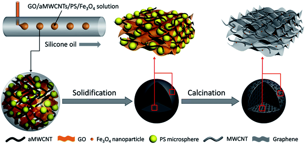 | ||
| Fig. 1 Schematic diagram of the fabrication process of MPGCBs via a microfluidic device. | ||
Oil absorption of MPGCBs in oil-in-water (O/W) mixtures
For the oil absorption of oil-in-water (O/W) mixtures, the absorption capacity for various oils and organic solvents was evaluated at room temperature. In a typical test, the MPGCBs were placed in contact with oils or organic solvents until the sample was filled with them completely. The weight measurements of the MPGCBs with absorbed organic liquid were done quickly to avoid evaporation of the absorbed material. The absorption capacity is calculated as α = (m − mo)/mo × 100 wt%, where m is the weight of sample after absorption and mo is the initial weight of the sample.Separation of water-in-oil (W/O) emulsions
For the separation of water-in-oil (W/O) emulsions, water-in-toluene, water-in-chloroform and water-in-hexane emulsions were labelled as S-1, S-2 and S-3, respectively. Typically, for the preparation of S-1, Span-80 (0.8 g) was added into toluene (150 mL) under vigorously stirring, followed by 1 mL water. The mixture was stirred for 5 h. The as-prepared emulsions with narrow size distribution were stable for 24 h. The specific preparation of S-2 and S-3 was supplied in Table S1.† The composition and the droplet size of three kinds of surfactant-stabilized emulsions were listed in Table S1.† The viscosity, refractive index and density of the oils used in oil/water separation experiment were summarized in Table S2.†The separation experiment was performed on a vacuum-driven filtration system, in which the height of the filtration cell was 80 mm and the diameter of the filter was 15 mm. The sandwich-like filtration membrane was made up of nylon filter membrane and a quantity of MPGCBs (0.25 g), and the schematic diagram of the preparation was shown in Fig. S11.† The diameter of particle-deposited area was 15 mm. The stable emulsion was poured into the filtration cell under a suction vacuum degree at 0.09 MPa.
Recyclability property of MPGCBs
The recyclability of the MPGCBs was characterized by combustion and distillation operations. After absorption to saturation, ethanol in the MPGCBs was burned off in air and reused for subsequent sorption experiments. The weights of MPGCBs before and after combustion process were recorded. The distillation method was used for heptane absorption experiment. After saturation absorption, the MPGCBs were heated to 95 °C to release the vapor of heptane, and then weighed and reused for subsequent absorption tests. Each sample was tested for 10 cycles of absorption/combustion and absorption/distillation.Characterization
The morphology was analyzed by using scanning electron microscope (SEM, S-4800) and transmission electron microscope (TEM, JEM-2100). FTIR data were obtained with ADVANCE III spectrometer in the range of 400–4000 cm−1 using potassium bromide pellet method. The X-ray diffraction (XRD) patterns of the samples were measured by a D8 ADVANCE diffractometer in the range of 5–80° (2θ-angle). Raman spectra were acquired using JY HR800 spectrometer which a 457.9 nm Ar+ ion laser was used as excitation source. X-ray photoelectron spectroscopy (XPS) was performed on a Kratos AXIS Ultra DLD spectrometer to clarify the element composition and binding energy of the samples. Contact angles were measured to investigate the wettability of MPGCBs using contact-angle device (Data physics, OAC20). Mechanical property measurement was recorded by a digital camera and an optical microscope (XTZ-D). Oil and organic solvent absorption process was described by optical images taken using a digital camera. Optical microscopy images were acquired using a BX51TF microscope. The oil purity in the filtrate was detected by a KF831 moisture titrator. Dynamic light scattering (DLS) measurement was performed on a Horiba SZ-100Z. UV-vis spectra were conducted with spectrometer Lambda 950.Results and discussion
It can be clearly shown in the insert picture of Fig. 2a that GO/aMWCNTs/PS/Fe3O4 beads had well sphericity and micro-scaled sizes. During the droplet formation process, superhydrophilic GO and aMWCNTs improved their dispersion degree in the droplets. The aMWCNTs maintained twisted structure after the acid treatment and GO displayed a crumpled surface, large and thin layers (Fig. S1†). The features of GO and aMWCNTs indicated that they are suitable for formation of stable and uniform dispersion in the microfluidic droplets (Fig. S2†). In the solidification process, PS microspheres tended to regular arrangement in the outer surface (Fig. 2a) and relative random in the interior of the beads (Fig. 2b). The existing of PS microspheres was not only beneficial for reducing obvious stacking between GO sheets and aMWCNTs, but also keeping the spherical shape. As shown in Fig. S5,† PS microspheres lost the whole weight when they were performed at 750 °C under N2 atmosphere. After the hard templates were completely removed at high temperature, the surface of the MPGCBs exhibited similarly honeycomb-like pores (Fig. 2c), while the interior formed interconnected porous network structure (Fig. 2d and S6†). And the MPGCBs still maintained integrally spherical characteristic due to the entanglement of GO sheets and aMWCNTs. When the mass ratios of GO and aMWCNTs changed from 10:0, 7:3, 5:5, 3:7 to 0:10, the abundant porous structure were existed in the all MPGCBs (Fig. S7†). As a result, this kind of 3D interconnected macropores provided the MPGCBs with abundant space for absorbing oils and organic solvents.
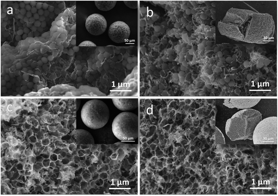 | ||
| Fig. 2 (a) and (b) were SEM images of the outer surface and the internal structure of GO/aMWCNTs/PS/Fe3O4 beads (inserted picture a), respectively. (c) and (d) were the outer surface and the internal structure of MPGCBs (inserted picture c), respectively. | ||
It can be seen from FTIR spectra of Fig. 3a and S4a† that the characteristic peaks of PS27,28 and the absorption band of carboxyl from GO and aMWCNTs obviously disappeared in MPGCBs, which indicated PS microspheres and part of hydrophilic groups were removed via calcination treatment. Through elemental composition analysis of XPS spectra in Fig. 3b, the similar conclusion can be drawn that MPGCBs had weaker intensity of O 1s peak and relative lower oxygen content than GO/aMWCNTs/PS/Fe3O4 beads. From the C 1s spectrum of MPGCBs (Fig. 3c), three component peaks centering at 284.4, 285.4 and 289.8 eV originated from C![[double bond, length as m-dash]](https://www.rsc.org/images/entities/char_e001.gif) C, C–O and CO groups, respectively.29 Due to the small amount of Fe3O4 nanoparticles in MPGCBs, there were no significant peaks in XPS broad spectra. However, XRD patterns (Fig. 3e and S3b†) indicated that there existed a series of peaks located at 30.20°, 35.5°, 43.3°, 53.4°, 57.1° and 62.5°, which related to the (220), (311), (400), (422), (511), and (440) planes of Fe3O4 nanoparticles,30 respectively. The further element state analysis in Fig. 3d showed XPS narrow spectrum had two distinct peaks at 711.0 and 724.0 eV which originated from Fe 2p3/2 and Fe 2p1/2 of Fe3O4 nanoparticles.30,31 The above results confirmed the magnetic property of the synthesized MPGCBs. After pyrolysis treatment, atomic structure or form of carbon materials can be changed and detected via XRD patterns and Raman spectra. In Fig. 3e, a weak peak at 10.70° belonging to the (001) profile of GO sheets29 and the characteristic diffraction band of PS (Fig. S4b†) both disappeared in MPGCBs. And a sharp peak centered at 25.9° in MPGCBs corresponding to the (002) plane of graphitic structure was still maintained.29,32,33 In addition, there were two peaks related to a defect D band at 1362 cm−1 and a broad G band at 1578 cm−1 in Raman spectra of Fig. 3f.34 The presence of D and G bands represented the defect of graphitic structures and the tangential vibration of sp2-bonded carbon atoms, respectively.33 And the intensity ratio between D band and G band (ID/IG) suggested the defect or disordered degree of carbon structures. It can be clearly seen that the ID/IG value of MPGCBs was higher than that of GO/aMWCNTs/PS/Fe3O4 beads, indicating MPGCBs had disorder degree and defects after calcination treatment.
C, C–O and CO groups, respectively.29 Due to the small amount of Fe3O4 nanoparticles in MPGCBs, there were no significant peaks in XPS broad spectra. However, XRD patterns (Fig. 3e and S3b†) indicated that there existed a series of peaks located at 30.20°, 35.5°, 43.3°, 53.4°, 57.1° and 62.5°, which related to the (220), (311), (400), (422), (511), and (440) planes of Fe3O4 nanoparticles,30 respectively. The further element state analysis in Fig. 3d showed XPS narrow spectrum had two distinct peaks at 711.0 and 724.0 eV which originated from Fe 2p3/2 and Fe 2p1/2 of Fe3O4 nanoparticles.30,31 The above results confirmed the magnetic property of the synthesized MPGCBs. After pyrolysis treatment, atomic structure or form of carbon materials can be changed and detected via XRD patterns and Raman spectra. In Fig. 3e, a weak peak at 10.70° belonging to the (001) profile of GO sheets29 and the characteristic diffraction band of PS (Fig. S4b†) both disappeared in MPGCBs. And a sharp peak centered at 25.9° in MPGCBs corresponding to the (002) plane of graphitic structure was still maintained.29,32,33 In addition, there were two peaks related to a defect D band at 1362 cm−1 and a broad G band at 1578 cm−1 in Raman spectra of Fig. 3f.34 The presence of D and G bands represented the defect of graphitic structures and the tangential vibration of sp2-bonded carbon atoms, respectively.33 And the intensity ratio between D band and G band (ID/IG) suggested the defect or disordered degree of carbon structures. It can be clearly seen that the ID/IG value of MPGCBs was higher than that of GO/aMWCNTs/PS/Fe3O4 beads, indicating MPGCBs had disorder degree and defects after calcination treatment.
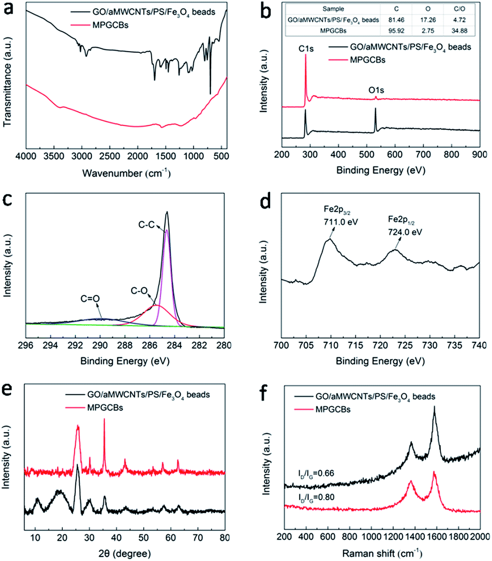 | ||
| Fig. 3 (a) FTIR spectra, (b) XPS spectra, (e) XRD patterns and (f) Raman spectra of GO/aMWCNTs/PS/Fe3O4 beads and MPGCBs. (c) and (d) were C 1s and Fe XPS spectra of MPGCBs, respectively. | ||
In order to explore hydrophobic performance of MPGCBs, the wetting behavior was measured via contact angle. It was clearly seen that water droplet with spherical shape stood on the surface of the tiled MPGCBs, and the tested contact angle was 152° (Fig. 4a). This phenomenon manifested that the MPGCBs lost hydrophilic functional groups after pyrolysis treatment, which were endowed with hydrophobic property. As shown in Fig. 4a, when oil droplet was deposited on the MPGCBs, it was absorbed instantaneously and the measured contact angle was around 0°. This result indicated that the interconnected macroporous structure was conductive to absorption of oils and organic solvents, and MPGCBs can be used as absorbents in water treatment field. When used as absorbents for oils and organic solvents, the materials need possess a certain mechanical property. Therefore, two detection modes containing compression and shear flow test were carried out. As shown in Fig. 4b, MPGCBs maintained well shape and no fragmentation phenomenon after loading a 100 g weight. Additionally, the robustness of MPGCBs was investigated under shear flow at different speed (Fig. 4c and Video S1†). The corresponding microscope photographs showed that MPGCBs still kept well sphericity after continuous stirring for 15 min in pure water, even though undergoing the speed of 400 rpm.
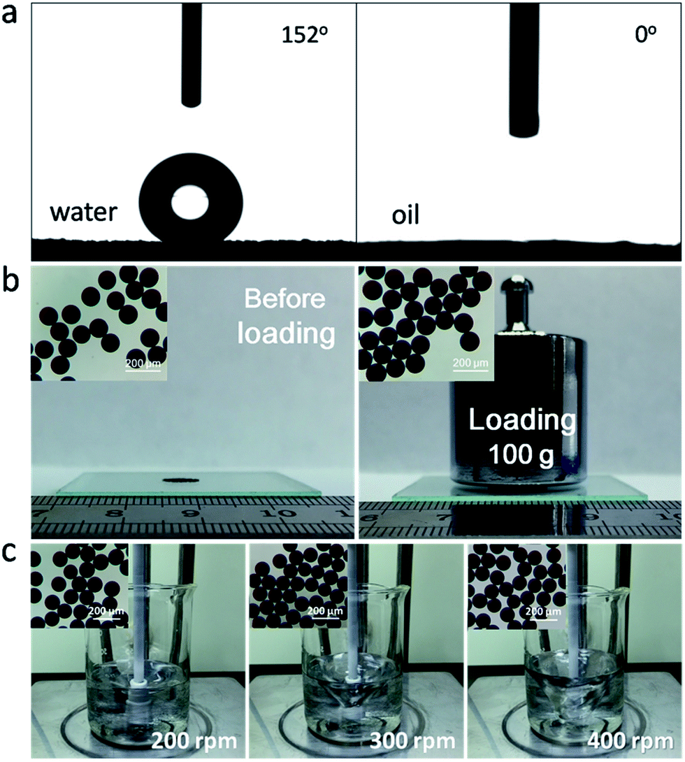 | ||
| Fig. 4 (a) Contact angle measurements of water and oil droplets on MPGCBs. (b) Digital photos of MPGCBs loading a 100 g weight and the corresponding microscope photographs. (c) Digital photos of MPGCBs in pure water system under continuous stirring for 15 min at different speed (200, 300, 400 rpm) and the corresponding microscope photographs. | ||
The MPGCBs possessed 3D macroporous structure and hydrophobicity, which made it a potential candidate for efficient removal of oils and organic solvents from water. As shown in Fig. S9a,† when a certain amount of MPGCBs were brought into contact with a pump oil layer (dyed with C. I. Pigment Orange) on water surface, they absorbed the oil completely within 30 s. A permanent magnet was utilized to capture the pollutants and pull MPGCBs together for recycling. Furthermore, MPGCBs can absorb organic solvent at the bottom of water such as chloroform (dyed with dark pink) quickly within 20 s (Fig. S9b†). The results suggested that porous structure and magnetic property not only enhanced the efficiency of absorption, but also promoted the collection of absorbents and the recovery of their absorbates.16
In order to further study the absorption capacity quantitatively, here the weight gain (%) is defined as the weight of absorbed substance per unit weight of the pristine MPGCBs.35,36 A series of oils and organic solvents with different surface tension were tested, including the commercial petroleum products (e.g. pump oil), fats (e.g. colza oil), hydrocarbons (e.g. heptanes, n-hexane), aromatic compounds (e.g. toluene), ketones (e.g. acetone), alcohols (e.g. methanol, ethanol, benzyl alcohol) and other organic solvents (e.g. chloroform, DMF), which are common pollutants in our daily life as well as from industry.35–37 It can be seen in Fig. 5 that MPGCBs exhibited a high absorption capacity of 8–25 times its own weight for the aforementioned oils and organic solvents. Importantly, MPGCBs showed higher absorption capacity than many previously reported sorbents, as listed in Table 1, such as activated carbons (<1 time),38 zolite (5 times),39 expanded perlite (3.2–7.5 times)40 and sawdust (3.77–6.4 times),41 PVP–iron oxide NPs (2.6 times),14 magnetic polymer nanocomposites (3.63 times),42 nanosheet-structured boron nitride spheres (NSBNSs) (7.8 times)17 and magnetic porous multi-walled carbon nanotube beads (MCNTBs) (6–18 times).23 Until now, owing to the lack of corresponding reports via microfluidic technology, this work enriched the family of 3D spherical carbon-based absorbents.
 | ||
| Fig. 5 Absorption capacity of MPGCBs for various kinds of oils and organic solvents. | ||
| Sorbent materials | Absorbed substances | Absorption capacity (g g−1) | Ref. |
|---|---|---|---|
| Activated carbons | Benzene, toluene | <1 | 38 |
| Zolite | ParaLux 701 process oil | 5 | 39 |
| Expanded perlite | Crude oil | 3.2–7.5 | 40 |
| Sawdust | Fatty acids, vegetable oils | 3.77–6.4 | 41 |
| PVP–iron oxide NPs | Crude oil | 2.6 | 14 |
| Magnetic polymer nanocomposites | Oils | 3.63 | 42 |
| NSBNSs | Pump oil | 7.8 | 17 |
| MCNTBs | Oils and organic solvents | 6–18 | 23 |
| MPGCBs | Oils and organic solvents | 8–25 | This work |
In W/O emulsions, MPGCBs can also smartly separate oil microdroplets via a homemade vacuum-driven filtration cell. A series of surfactant-stabilized water-in-oil emulsions, including water-in-toluene (S-1), water-in-chloroform (S-2) and water-in-hexane (S-3), were prepared to evaluate the separation capability of MPGCBs. Take S-1 for example, after the emulsion was slowly poured into the container, only toluene selectively passed through the fixed MPGCBs and water was still remained in the membrane surface due to the water-repellency of MPGCBs (Fig. 6A). Optical microscopy images of the original feed and the collected filtrate were taken to characterize the separation effectiveness. As shown in Fig. 6B, numerous water droplets with an average diameter of 190 nm were observed in the feed solution and there were no droplets in the collected filtrate. Optical microscopy images of S-2 and S-3 were provided in Fig. S7.† Briefly, it can be assumed that MPGCBs possessed the outstanding W/O separation performance.
 | ||
| Fig. 6 (A) Digital photographs and schematic diagram of water-in-toluene (S-1) emulsion separation process, (B) photographs, optical microscopy images and DLS data of the feed and the corresponding filtrate for S-1 emulsion. | ||
To further evaluate separation efficiency, the water content and oil purity in the collected filtrate were investigated by UV-vis spectrometer and moisture titrator, respectively (Fig. S13 and S14a†). For S-1 emulsion, the characteristic peak of toluene was not observed in the filtrate spectrum (Fig. S13a†), and the oil purity of the collected filtrate can be up to 99.92% (Fig. S14a†). Additionally, S-2 and S-3 emulsions also achieved effective separation and the oil purity were 99.94% and 99.96% in their corresponding filtrate (Fig. S13b, 13c and S14a†). The results indicated the excellent separation efficiency of MPGCBs. As shown in Fig. S14b,† the fluxes of various emulsions permeating through the filtration cell were also measured, and all the fluxes were achieved by calculating the penetrated volume of emulsions in the certain time. For separating W/O emulsions, the viscosity of the oil is a crucial factor, which showed a higher flux for oil with a lower viscosity.43 Three different kinds of oils were chosen to study in our experiment (Table S2†). It can be seen that S-3 emulsion with the lowest viscous presented the highest flux (∼500 L m−2 h−1 bar−1) in all W/O emulsions.
Pollution control and environmental protection efforts require that not only the absorbents are provided with outstanding recoverability, but also the absorbates can be properly recycled and thus reused, because most pollutants are either precious raw materials or toxic, e.g., crude oil and toluene.36,37 According to the features of MPGCBs, there are two common methods containing combustion and distillation for recycling tests. The combustion process was applicable for the effective removal of the flammable and useless pollutants, such as ethanol (Fig. S16a†). And distillation operation was suitable for the recycling of valuable pollutants or those with low boiling points, such as heptane (Fig. S16b†). It can be seen in Fig. 7a that the cyclic combustion test demonstrated that the absorption capacity of MPGCBs after 10 cycles only decreased by 2.58 wt% in comparison with absorption capacity in the first cycle, most likely due to the deposition of residues on the surface or in the internal of the beads after combustion. To demonstrate distillation test, heptane (boiling point, 98.5 °C) was absorbed by MPGCBs. The absorption/distillation process was repeated up to 10 times as well as the combustion process to investigate its recyclability (Fig. 7b). In this test, the beads were heated to 95 °C to release the vapour of heptane.44 It was obviously seen that less than 1 wt% of residual heptane remained after 10 cycles, and the absorption capacity of the beads showed negligible change. The results indicated that MPGCBs had stable absorption capacity and recycling performance.
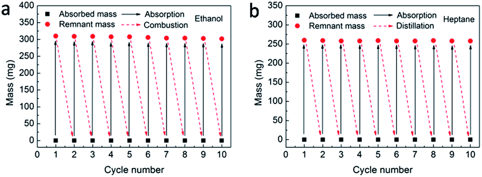 | ||
| Fig. 7 (a) and (b) were the recyclability investigation of MPGCBs after combustion and distillation, respectively. | ||
Conclusion
In summary, MPGCBs with 3D interconnected porous architectures have been successfully fabricated by a modified capillary microfluidic device. When used for the removal of pollutants, the MPGCBs with outstanding hydrophobic property and porous structures possessed a high absorption capacity of 8–25 times its own weight. Furthermore, they also can effectively separate a series of surfactant-stabilized water-in-oil emulsions with excellent separation efficiency. The additional Fe3O4 nanoparticles endowed the beads with flexibility, which can not only facilitate the movement, but also promote the collection and recovery of oil contaminants. The MPGCBs can be recycled and repeatedly used via a simple method of combustion or distillation. Importantly, unique spherical feature and novel preparation method make it effective for possible practical application. Therefore, this new class of multi-functional MPGCBs enriched the family of carbon-based sorbents and they can be used as an ideal candidate for absorbent in water treatment.Acknowledgements
The present study has been supported by NSFC (51473056, 51573015, 51527804, 51372072 and 21372067), the Scientific Research Foundation committee for the Returned Overseas Chinese Scholars of Heilongjiang Province (LC2016003), Outstanding Youth Science Foundation Committee of Heilongjiang University (JCL201202), Heilongjiang Province Basic Scientific Research Special Fund of Heilongjiang University (HDJCCX-201616), and Postgraduate Innovative Research Program of Heilongjiang University (YJSCX2015-080HLJU).Notes and references
- J. L. Ge, J. C. Zhang, F. Wang, Z. L. Li, J. Y. Yu and B. Ding, J. Mater. Chem. A, 2017, 5, 497–502 CAS.
- J. Li, R. M. Kang, X. H. Tang, H. D. She, Y. X. Yang and F. Zha, Nanoscale, 2016, 8, 7638–7645 RSC.
- X. J. Zeng, L. Qian, X. X. Yuan, C. L. Zhou, Z. W. Li, J. Cheng, S. P. Xu, S. F. Wang, P. H. Pi and X. F. Wen, ACS Nano, 2017, 11, 760–769 CrossRef CAS PubMed.
- Z. J. Wang, G. J. Liu and S. H. Huang, Angew. Chem., 2016, 128, 14830–14833 CrossRef.
- L. R. Shi, K. Chen, R. Du, A. Bachmatiuk, M. H. Rümmeli, K. W. Xie, Y. Y. Huang, Y. F. Zhang and Z. F. Liu, J. Am. Chem. Soc., 2016, 138, 6360–6363 CrossRef CAS PubMed.
- H. Zhu and Z. G. Guo, Journal of Bionic Engineering, 2016, 13, 1–29 CrossRef.
- S. Song, H. Yang, C. P. Su, Z. B. Jiang and Z. Lu, Chem. Eng. J., 2016, 306, 504–511 CrossRef CAS.
- C. L. Zhou, Z. D. Chen, H. Yang, K. Hou, X. J. Zeng, Y. F. Zheng and J. Cheng, ACS Appl. Mater. Interfaces, 2017, 9, 9184–9194 CAS.
- X. Lin, Y. N. Chen, N. Liu, Y. Z. Cao, L. X. Xu, W. F. Zhang and L. Feng, Nanoscale, 2016, 8, 8525–8529 RSC.
- S. Yang, Y. Si, Q. X. Fu, F. F. Hong, J. Y. Yu, S. S. Al-Deyab, M. El-Newehyc and B. Ding, Nanoscale, 2014, 6, 12445–12449 RSC.
- J. Li, C. C. Xu, Y. Zhang, R. F. Wang, F. Zha and H. D. She, J. Mater. Chem. A, 2016, 4, 15546–15553 CAS.
- Y. B. Peng and Z. G. Guo, J. Mater. Chem. A, 2016, 4, 15749–15770 CAS.
- Z. J. Wang, Y. Wang and G. J. Liu, Angew. Chem., 2016, 128, 1313–1316 CrossRef.
- S. Palchoudhury and J. R. Lead, Environ. Sci. Technol., 2014, 48, 14558–14563 CrossRef CAS PubMed.
- C. T. Duan, T. Zhu, J. Guo, Z. Wang, X. F. Liu, H. Wang, X. Xu, Y. Jin, N. Zhao and J. Xu, ACS Appl. Mater. Interfaces, 2015, 7, 10475–10481 CAS.
- J. Wang, L. R. Shang, Y. Cheng, H. B. Ding, Y. J. Zhao and Z. Z. Gu, Small, 2015, 11, 3890–3895 CrossRef CAS PubMed.
- F. Liu, J. Yu, X. X. Ji and M. Q. Qian, ACS Appl. Mater. Interfaces, 2015, 7, 1824–1832 CAS.
- L. Y. Chu, A. S. Utada, R. K. Shah, J. W. Kim and D. A. Weitz, Angew. Chem., Int. Ed., 2007, 46, 8970–8974 CrossRef CAS PubMed.
- B. F. Ye, H. B. Ding, Y. Cheng, H. C. Gu, Y. J. Zhao, Z. Y. Xie and Z. Z. Gu, Adv. Mater., 2014, 26, 3270–3274 CrossRef CAS PubMed.
- L. R. Shang, F. Q. Shangguan, Y. Cheng, J. Lu, Z. Y. Xie, Y. J. Zhao and Z. Z. Gu, Nanoscale, 2013, 5, 9553–9557 RSC.
- L. R. Shang, Y. Cheng, J. Wang, H. B. Ding, F. Rong, Y. J. Zhao and Z. Z. Gu, Lab Chip, 2014, 14, 3489–3493 RSC.
- Y. Cheng, F. Y. Zheng, J. Lu, Z. Y. Xie, Y. J. Zhao, Y. P. Cheng and Z. Z. Gu, Adv. Mater., 2014, 26, 5184–5190 CrossRef CAS PubMed.
- X. J. Cao, L. L. Zang, Z. P. Bu, L. G. Sun, D. C. Guo and C. Wang, J. Mater. Chem. A, 2016, 4, 10479–10485 CAS.
- L. L. Zang, X. J. Cao, Y. H. Zhang, L. G. Sun, C. L. Qin and C. Wang, J. Mater. Chem. A, 2015, 3, 22088–22093 CAS.
- Z. Z. Gu, H. H. Chen, S. Zhang, L. G. Sun, Z. Y. Xie and Y. Y. Ge, Colloids Surf., A, 2007, 302, 312–319 CrossRef CAS.
- J. Liu, Z. K. Sun, Y. H. Deng, Y. Zou, C. Y. Li, X. H. Guo, L. Q. Xiong, Y. Gao, F. Y. Li and D. Y. Zhao, Angew. Chem., Int. Ed., 2009, 48, 5875–5879 CrossRef CAS PubMed.
- S. Zhou, W. Jiang, T. H. Wang and Y. Lu, Ind. Eng. Chem. Res., 2015, 54, 5460–5467 CrossRef CAS.
- G. H. Qiu, Q. Wang, C. Wang, W. Lau and Y. L. Guo, Ultrason. Sonochem., 2007, 14, 55–61 CrossRef CAS PubMed.
- M. Q. Sun, G. C. Wang, X. W. Li and C. Z. Li, J. Power Sources, 2014, 245, 436–444 CrossRef CAS.
- C. Wu, Q. C. Zhuang, Y. X. Wu, L. L. Tian, Y. L. Cui and X. X. Zhang, Mater. Lett., 2013, 113, 1–4 CrossRef CAS.
- D. J. Han, J. H. Jung, J. S. Choi, Y. T. Kim and T. S. Seo, Lab Chip, 2013, 13, 4006–4010 RSC.
- S. S. J. Aravind and S. Ramaprabhu, RSC Adv., 2013, 3, 4199–4206 RSC.
- B. P. Vinayan, R. Nagar, V. Raman, N. Rajalakshmi, K. S. Dhathathreyanb and S. Ramaprabhu, J. Mater. Chem., 2012, 22, 9949–9956 RSC.
- L. H. Chang, C. K. Hsieh, M. C. Hsiao, J. C. Chiang, P. I. Liu, K. K. Ho, C. C. M. Ma, M. Y. Yen, M. C. Tsai and C. H. Tsai, J. Power Sources, 2013, 222, 518–525 CrossRef CAS.
- L. L. Zang, Z. P. Bu, L. G. Sun and Y. H. Zhang, RSC Adv., 2016, 6, 48715–48719 RSC.
- H. C. Bi, X. Xie, K. B. Yin, Y. L. Zhou, S. Wan, L. B. He, F. Xu, F. Banhart, L. T. Sun and R. S. Ruoff, Adv. Funct. Mater., 2012, 22, 4421–4425 CrossRef CAS.
- Y. Q. Li, Y. A. Samad, K. Polychronopoulou, S. M. Alhassan and K. Liao, ACS Sustainable Chem. Eng., 2014, 2, 1492–1497 CrossRef CAS.
- M. A. Lillo-Ródenas, D. Cazorla-Amorós and A. Linares-Solano, Carbon, 2005, 43, 1758–1767 CrossRef.
- T. Sakthivel, D. L. Reid, I. Goldstein, L. Hench and S. Seal, Environ. Sci. Technol., 2013, 47, 5843–5850 CrossRef CAS PubMed.
- D. Bastani, A. A. Safekordi, A. Alihosseini and V. Taghikhani, Sep. Purif. Technol., 2006, 52, 295–300 CrossRef CAS.
- S. S. Banerjee, M. V. Joshi and R. V. Jayaram, Chemosphere, 2006, 64, 1026–1031 CrossRef CAS PubMed.
- J. J. Gu, W. Jiang, F. H. Wang, M. D. Chen, J. Y. Mao and T. Xie, Appl. Surf. Sci., 2014, 301, 492–499 CrossRef CAS.
- J. C. Gu, P. Xiao, J. Chen, J. W. Zhang, Y. J. Huang and T. Chen, ACS Appl. Mater. Interfaces, 2014, 6, 16204–16209 CAS.
- H. C. Bi, Z. Y. Yin, X. H. Cao, X. Xie, C. L. Tan, X. Huang, B. Chen, F. T. Chen, Q. L. Yang, X. Y. Bu, X. H. Lu, L. T. Sun and H. Zhang, Adv. Mater., 2013, 25, 5916–5921 CrossRef CAS PubMed.
Footnote |
| † Electronic supplementary information (ESI) available. See DOI: 10.1039/c7ra03910g |
| This journal is © The Royal Society of Chemistry 2017 |