 Open Access Article
Creative Commons Attribution 3.0 Unported Licence
Fabrication of BN membranes containing high density of cylindrical pores using an elegant approach†
C. Marichy*a,
V. Sallesa,
X. Jaurandb,
A. Etiemblec,
T. Douillard c,
J. Faugier-Tovara,
F. Cauweta and
A. Brioudea
aUniv Lyon, Université Claude Bernard Lyon 1, Laboratoire des Multimatériaux et Interfaces, UMR CNRS 5615, F-69622 Villeurbanne, France. E-mail: catherine.marichy@univ-lyon1.fr
bCentre Technologique des Microstructures, Université de Lyon, Villeurbanne, F-69622, France
cUniv Lyon, INSA Lyon, MATEIS UMR CNRS 5510, F-69621 Villeurbanne, France
First published on 10th April 2017
Abstract
A high quality BN membrane with millions of through cylindrical pores is simply fabricated using a double inversion approach combining atomic layer deposition and polymer-derived ceramic route. Well crystallized hexagonal boron nitride walls are obtained at relatively low temperature (1000 °C). This new membrane is a promising candidate for osmotic energy conversion and water filtration applications.
Energy conversion and water filtration are two of the most important challenges for the coming decades. In recent years, researchers have put lot of effort into nanofluidics in order to find the best material for such applications.1–11 The most investigated materials are carbon and hexagonal boron nitride (h-BN), because of their high surface charge, either as monolayers or as nanotubes (NT). Recently, Siria et al. demonstrated that a single boron nitride nanotube (BNNT) can generate huge osmotically induced electric currents when it is submitted to salinity concentration gradients.9
The new challenge arising then is how to fabricate membranes containing an assembly of high quality BNNTs in order to harvest power from osmotic energy and to use them as efficient water filters simultaneously. Recent papers described the preparation of highly porous and freestanding BN materials using aerogels and freeze drying process.12,13 Fabrication of porous BN has been investigated by template-assisted method, with chemical vapor deposition (CVD)14,15 or liquid ceramic precursor infiltration.16 For instance, superelastic and macroporous h-BN structures have already been reported using ammonia-borane based CVD on a nickel foam template,15 while BNNTs have successfully been prepared using a template infiltrated with either gases (CVD) or liquids.16,17 However, none of these freestanding ultralight structures seem to combine a sufficiently thin (lower than 50 nm) and organized porosity with a short length of the tubes (a few μm). This suited aspect ratio is essential to achieve a giant osmotic energy conversion.9 Furthermore, a material deposition by CVD on a rough or porous substrate usually leads to clogging/masking effects. In case of membrane infiltration, this phenomenon can lead to the formation of a gradient of the wall thickness. The same lack of control of the wall geometry can be observed with a liquid impregnation of membranes. For instance, Bechelany et al.16 reported impregnation of anodic aluminium oxide (AAO) with a liquid polyborazylene, a BN preceramic polymer, followed by high temperature treatment. Tubes instead of rods were obtained because of evaporation of low molecular weight species during the annealing. It should also be noted that h-BN is only detected after annealing at 1800 °C and the final structure is dependent of the starting AAO membrane morphology/size. Other strategies such as arc discharge,18 and pyrolysis of molecular precursors19 do not produce freestanding membrane with organized porosity. Up to now the only nanochannel arrays matching with requirements of osmotic energy conversion were fabricated from h-BN layer etched by a focused ion beam (FIB).20 This approach is highly expensive and not applicable at large scale.
Due to its very high conformality and versatility, atomic layer deposition (ALD) appears as an ideal technique for elaborating such materials at reasonable cost.21–24 Few ALD approaches of BN have already been reported in the literature, however up to now, they are mostly ammonia based process25–28 at one exception29 and none leads to very high quality h-BN.
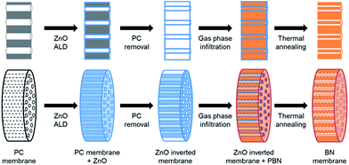
In the present study, a new ammonia free approach is proposed to fabricate well crystallized hexagonal BN membranes containing several thousands of cylindrical pores with tunable size from a few tens to hundreds of nanometers making them fully compatible with osmotic energy conversion and water filtration. Using a double inversion approach combining atomic layer deposition and polymer derived ceramic (PDC) route (scheme depicted in Fig. 1), good quality and large surface BN membranes were elaborated from a commercially available polymer membrane. ALD performed at low temperature (50–150 °C) is interesting to perform material depositions on a wide range of templates, even on polymeric membranes. Thanks to this step, the proposed approach is very versatile in terms of kind of geometry and size of porosity, paving the way to materials that fulfill the osmotic energy conversion requirement. It should be noted that such high versatility combined with very good crystal quality was not allowed up to now by previously reported approaches, including templating. This certainly represents a step forward to harvest power from osmotic energy.
Experimental
Isopore™ polycarbonate (PC) membranes (Millipore HTTP02500) of 0.4 μm pore size, 25 mm in diameter and a thickness of 10 μm thick were used as template for double inversion. They contain a high density of through cylindrical pores having an average diameter of 0.4 μm. Fig. 1 summarizes the fabrication process.Zinc oxide (ZnO) inversion
PC membranes were first partially infiltrated with ZnO by atomic layer deposition. Depositions took place in a home-made ALD reactor working in continuous flow at 100 °C. A silicon wafer was coated simultaneously as reference. Diethyl zinc and deionized water were used as metal and oxygen sources respectively, and introduced alternately by pneumatic ALD valves, from their respective stainless steel reservoirs kept at 25 °C. An opening time of 0.3 s followed by a purge of 15 s were set for both precursors. For the deposition, pure argon was used as carrier gas at a constant flow rate of 200 sccm. Considering a growth per cycle of 0.7 Å into the membrane, the number of ALD cycles performed varied from 1400 to 2000 cycles. A subsequent calcination at 550 °C for 30 min under air was realized to remove the PC template. In agreement with PC membrane thermal gravimetric analysis, a slow ramp of 1 °C per min was used. The thermal decomposition of PC was then performed at 550 °C, an intermediate dwelling at 410 °C for 3 h was chosen to thermally decompose the polymer without deteriorating the ZnO structures.Borazine infiltration
Borazine was synthesized in the lab with a previously described procedure.30 The hollow oxide structures were subsequently infiltrated with polyborazylene via its exposition to borazine vapor. In a glovebox, a 23 ml Teflon-lined stainless steel autoclave including a 1.2 ml Teflon crucible was filled with 1 ml of borazine. On the top of the 1.2 ml filled crucible a holey aluminium grid was placed holding the vertical structuration of ZnO pores. This setup permits the oxide structure to be infiltrated with borazine vapor without any contact with the liquid phase. Polymerization of the boron precursor took place at 58 °C for 7 days (ramp of 1 °C h−1). After cooling, the infiltrated structures were transferred under inert atmosphere into a tubular oven. Subsequent thermal annealing at 1000 °C for 2 h under N2 allows the conversion of polyborazylene into BN, leading to a well-crystallized BN membrane.Characterization
Scanning electron microscopy (SEM) images and Energy dispersive X-ray spectra (EDXS) were recorded using a Zeiss Merlin VP compact and a FEI Quanta FEG 250 microscopes operating at 5 and 15 kV with, respectively, a SDD OXFORD X-Max and SAMx Premium EDXS detectors. ZnO and BN structures were characterized by transmission electron microscopy (TEM) using a JEOL 2100F. Cross sections were realized after membrane infiltration using a resin. Tomography analyses were realized in TEM and Scanning TEM (STEM) mode by tilting the sample from −60 to 60°, using a JEOL 2100F microscope. Focused ion beam (FIB)/SEM tomography was performed on a cross section using a Carl Zeiss NVision 40 workstation combining a SIINT zeta FIB column (Seiko Instruments Inc. NanoTechnology, Japan) with a Gemini I SEM column with an angle of 54° between both columns. The BN membrane pores were filled with epoxy resin. A carbon layer (10 × 10 × 1 μm3) was deposited on the top of the sample by in situ ion beam induced deposition to protect the surface during slicing in order to achieve sharp upper edges and minimize curtaining artefacts. Three reference lines were imprinted into the carbon layer using the ion beam for post-stack alignment purpose. Serial SEM imaging was done in both secondary electron (SE) and In-Lens (ILE) modes with an accelerating voltage of 1.5 keV. Serial FIB sectioning was performed with a current of 3 nA at 30 keV and an incremental step of 10 nm. 3D reconstruction of the membrane was performed with a voxel size of 10 × 10 × 10 nm3 from stacks of 1000 images, corresponding to a volume of 15 × 15 × 10 μm3. After acquisition, Fiji software was used for the image processing, 3D reconstruction and morphological quantification, as described in ref. 31. The morphological parameters of the BN membrane extracted from these analyses are summarized in Table S1.†Raman spectra were recorded with an exciting wavelength of 532 nm using a LabRam HR, Jobin Yvon spectrometer. The wetting properties were characterized with depositing 1–5 μl of deionized water using a Krüss Easydrop. Thermal gravimetry analysis (TGA) of PC membrane was realized under air from RT up to 1000 °C with a heating ramp of 5 °C min−1 using a TGA851 Metler Toledo thermobalance. Brunauer–Emmett–Teller (BET) measurement was performed by a Microtrac Bel BelSorp-Mini II using N2 adsorbing gas. X-ray diffraction (XRD) measurement was recorded using a BRUKER D8 Advance diffractometer with a step time of 614.4 s and step size of 0.0205°. X-ray photoelectron spectroscopy was performed, using a PHI Quantera SXM spectrometer with Al Kα monochromatism radiation, to characterize the composition of final materials. Analysed area is of 200 μm diameter. Abrasion with Ar ion of approximately 20 nm was realized at 2 kV on 1.5 × 1.5 mm2.
Results and discussion
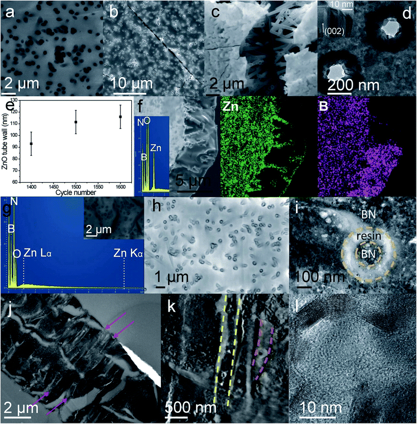
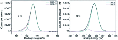
First, Isopore® polycarbonate membranes (Fig. 2a) were infiltrated with ALD zinc oxide at low temperature. ZnO was chosen as intermediate template material because of its wurtzite (hexagonal phase) crystalline structure, which makes it suitable for borazine (BN precursor that shows aromatic unit) self-organization on its surface, and its amphoteric properties permitting its easy removal. Furthermore, ZnO, which is crystalline even at low temperature, is stable at relatively high temperature without crystal phase modification that could alter the final BN structure during the annealing process. Finally, ZnO ALD can be performed at near room temperature widening the range of potential substrates compared to other approaches such as CVD. Due to the very high conformity of the ALD coating, well defined arrays of ZnO tubes or rods (hollow or full structures, respectively). This inner diameter can be adjusted by monitoring the number of ALD cycles. After removal of the polymer scaffold, self-standing crossing hollow tubes made of polycrystalline oxide can be obtained (Fig. 2b–e) (see Fig. S1 in (ESI†) for measurement accuracy). As a function of the number of cycles realized, infiltration of PC template can be tuned from partial to full filling. Template removal permits thus obtaining arrays of either tubes or rods, respectively, as previously demonstrated using photonic structures.32 Then, exposition of these arrays to borazine vapors for several days at 58 °C led to their conformal complete infiltration with BN-based polymer. Indeed, borazine molecules polymerize with a slow self-condensation process within a few days either into solid polyborazylene at temperature > 60 °C, or into viscous liquid polyborazylene at lower temperature (45–60 °C).33 A low vapor infiltration temperature was chosen in this case to favor the organization of the borazine rings on the ZnO surface while maintaining self-condensation. EDXS spectrum confirms the presence of B and N elements into the metal oxide tube array after 7 days of borazine exposure into an autoclave. Polyborazylene formation seems to be homogenous and conformal inside the whole hollow ZnO structure (Fig. 2f), as highlighted by EDXS mapping. Zn element (green color) is only detected along the tubes while B element (purple) is distributed over the whole structure. Finally, conversion of polyborazylene into pure boron nitride and removal of the ZnO scaffold were directly realized via a single annealing step at high temperature (1000 °C) under nitrogen atmosphere. Contrary to routes using inorganic templates such as Cu foam and AAO, none post-treatment or chemical etching is required within this process. Removal of ZnO during the thermal treatment was confirmed by EDXS analysis (Fig. 1g) which detected only boron, nitrogen and a small amount of oxygen. Elimination of ZnO is promoted by the ceramic transformation that releases hydrogen which in turns reduces zinc oxide into Zn0. Having a boiling point at 906 °C, the latter evaporates during the annealing process taking place at 1000 °C. No detectable zinc element is observed using EDXS and XPS (See in ESI, Table S1†), meaning a Zn concentration below the detection limit of 0.1 at%. XPS reveals also a perfect stoichiometry of the material with a B/N ratio of 1.0. The survey spectra and high resolution spectrum (Fig. S2, ESI†) does not reveal any Zn related peak. Deconvoluted B 1s and N 1s XPS peaks, see high resolution spectra shown in Fig. 3, are centered, respectively, at 190.7 and 398.2 eV, in very good agreement with BN.Furthermore, BN membranes with similar morphology to the original polymer template were successfully obtained as shown in the Fig. 2h. A small shrinkage of 15–20% was observed after pyrolysis. One should note the presence of a concentric structure of BN, with a rods inside each pores (Fig. 2h and i). This configuration arises from fabrication of ZnO tube array instead of a rod array. Borazine infiltrated thus the void of the array as well as the inner cavity of ZnO tubes. By choosing the appropriate ALD cycle number, BN membranes with either annular (as shown in Fig. 2i) or cylindrical pores can then easily be fabricated. The annular through porosity with BN rod in its center is observed in the bright field TEM images (Fig. 2i and j) and scanning TEM (STEM) image (Fig. 2k) recorded from a cross section. Void appears in bright contrast. A certain tortuosity of the pores combined with the thinness of the cross section renders the observation of annular pores along the whole membrane thickness difficult. The dimension of the empty ring can be tuned by controlling the ZnO wall thickness, from a few tens to hundreds of nm. This point is crucial in view of osmotic conversion application.
In addition to the confirmation of the open porosity, stitching of low magnification (Fig. 2j) TEM images (in ESI, Fig. S3†) recorded on membrane cross-section reveal presence of larger voids that might result from membrane manipulation and/or the very close proximity of some pores.
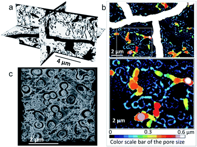
As shown by the reconstructed 3D view in Fig. 4a and c, FIB/SEM tomography analysis performed on a cross-sectioned membrane confirms the presence of both cracks and open annular pores, with an important connectivity (97.8%) (ESI, Table S2†). One should note the presence of empty rings visible in the middle planes of the cross section (Fig. 2a), supporting a through porosity. The video of pore architecture presented in ESI shows the open annular porosity, which presents an average diameter of 120 nm when 1500 cycles ZnO tube array is as intermediate (ESI, Table S2 and video S1†). In plane pore size distributions are depicted in Fig. 4b. Furthermore, pore disorientation is observed despite a dominant orientation along the z axis (i.e. membrane thickness), as demonstrated by the lower pore geometrical tortuosity in this direction (ESI, Table S2†). This property is directly linked to the starting polymer template geometry.
A specific surface area (SSA) superior to 10 m2 g−1, in agreement with the minimum calculated theoretical one (∼5 m2 g−1, see ESI†), was also determined based on the FIB/SEM analysis. Taking into account the experimental conditions (resolution) used to perform FIB/SEM tomography, one can say that only macroporosity (larger than 50 nm) can be characterized. Brunauer–Emmett–Teller (BET) analysis, presented in ESI (Fig. S4†), was also attempted on half membrane to roughly estimate the porosity and specific surface area of the BN material. However, because of the lightness of the material (which is highly porous), the quantity of analyzed material (≈1 mg) was insufficient for obtaining relevant and clear results. Adsorption/desorption curves with such a small amount might only suggest a greater SSA than 10 m2 g−1 and thus an eventual second order of porosity. This is in good agreement with the surface calculated (see ESI† for this calculation on SSA), taking into account a cylindrical pore with a diameter of 0.4 μm, containing a rod with a diameter of 0.2 μm. The calculation leads to a SSA of 5 m2 g−1, for a number of pores of 4.9 × 10⁸ pores. The surface availability of hundreds of millions of small pores in a single membrane confirms the interest of the present synthesis approach to strongly increase the number of nanochannels able to generate osmotically induced electric currents. More finely, meso- and micro-porosity were simultaneously investigated by TEM and STEM tomography. Mesopores with diameter ranging from 3 to 15 nm are observed in TEM (ESI, Fig. S5†) images extracted from the recorded stacks. This is certainly an advantage for hydrogen storage and water purification application. The mesopore interconnectivity has not been confirmed yet, even though it is suggested by the BET analysis. Such open porosity will be advantageous for osmotic energy conversion and hydrogen storage in case of well crystallized material. According to theoretical study,9 high BN crystallinity appears suited to increase the energy conversion rate, indeed.
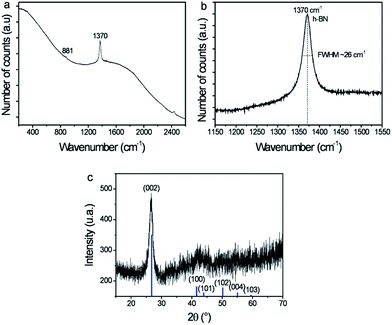
TEM investigation (Fig. 2l) at high magnification demonstrated the formation of highly crystallized boron nitride after pyrolysis. Lattice fringes, attributed to h-BN, are shown in the Fig. 2l. Raman spectroscopy and X-ray diffraction (XRD), presented in the Fig. 5, confirm the BN crystallization into hexagonal phase. The recorded XRD pattern (Fig. 5c) displayed a narrow peak at 26.7°, characteristic of the (002) h-BN planes. Furthermore, large frequency Raman spectrum (Fig. 5a) reveals a very sharp band centered at 1370 cm−1, characteristic of h-BN E2g mode, as well as a weak band at 881 cm−1 corresponding to a very low amount of B–O bonds.34 Despite a small boron oxidation, it should be noted that the full width at half maximum (FWHM) of the BN band is 26 cm−1, sign of very good crystal quality. This value is comparable to that of other works at higher temperature, indeed. The best h-BN crystals reported so far showed FWHM around 7.7–9 cm−1 and were obtained at temperature above 1200 °C using either molten salt synthesis35 or a spark plasma sintering assisted PDC route.36 Recently, Yuan et al. reported the addition of crystallization promoter, Li3N, into polyborazylene synthesis. BN crystals with Raman FWHM of 38 and 17 cm−1 were obtained using this promoter after annealing at 1200 and 1400 °C, respectively, while pure polyborazylene treated at 1400 °C showed a Raman band with FWHM equal to 52 cm−1.37,38 Narrower Raman bands (FWHM = 14 cm−1) were recorded from BN fabricated by PDC route after annealing at 1800 °C.39 One can thus hypothesize that the ZnO hexagonal structure combined with a slow vapor process at low temperature favors the BN crystallization. It might be attributed to a primary 2D organization of borazine rings on the wurtzite ZnO surface. The hexagonal crystalline phase observed here is similar to that of BN nanotube with which giant osmotic conversion was previously reported.9 It is worthy to note that high quality BN membrane, suitable for energy conversion, was successfully obtained using gentle infiltration condition and relatively mid temperature annealing for such ceramic. Indeed, using PDC route without additive required at least 1600 °C to obtain similar crystallinity.37
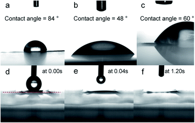
The wetting properties were also investigated by water contact angle measurement (Fig. 6). The water drop penetrated into the PC membrane after several seconds. Infiltration of this membrane with ZnO increased its hydrophilicity (water angle changing from 84° to 48°). Freestanding ZnO tube array demonstrated high hydrophilic behavior with instantaneous disappearance of the water drop as shown in the micrographs in the Fig. 6d–f. Finally, BN material demonstrated weak hydrophobicity, as expected.40 Water drop on BN membrane showed a contact angle of 60°, in agreement with the hydrophobic character of the BN material.40 It is worthy to note that a water contact angle of 60° reveals also a weak hydrophilic property which is required for osmotic energy conversion.
Conclusions
To conclude, thanks to gentle infiltration conditions, the initial PC membrane structure is well-preserved despite the multiple steps. The presented double inversion approach, which combined ALD and PDC routes, even though time consuming, permits versatile fabrication of boron nitride membrane with control of the through porosity in terms of shape and size that could not be achieved so far by previous reported approaches. Indeed, the use of ALD, for primary inversion step, allows the tuning of the pore diameter as well as the creation of a sub-network of BN nanorods included into the primary membrane, when ZnO nanotubes array are formed instead of full nanorods. This approach gives the opportunity to prepare self-standing BN membranes with hundreds of millions of cylindrical pores, highly crystallized and characterized by a size ranging from a few tens to several hundreds of nm, with a few μm long. Even if the brittleness of those freestanding membranes is currently an issue for their final use, it is possible to insert the membranes into a suitable porous support which could stand the external mechanical constraints and maintain the membrane integrity. Even if this next step still has to be demonstrated here, it is thus possible to argue that those membranes are highly promising candidates for osmotic energy application, and maybe for water filtration.Acknowledgements
The authors gratefully acknowledge the CECOMO (Université Lyon 1) for providing access to Raman facilities. They also thank F. Gombault (LMI) for the borazine synthesis, C. Journet (LMI) for TEM observations, as well as M. Maillard and F. Chassagneux (LMI) for fruitful discussions. Thanks are also due to the CLYM (Centre Lyonnais de Microscopie: http://www.clym.fr) supported by the CNRS, the “Grand Lyon” and the Rhône-Alpes Region for the use of the Zeiss NVision40 FIB/SEM and “Science et surface” is acknowledged for the XPS characterizations.Notes and references
- L. Bocquet and E. Charlaix, Chem. Soc. Rev., 2010, 39, 1073–1095 RSC.
- D. Cohen-Tanugi and J. C. Grossman, Nano Lett., 2012, 12, 3602–3608 CrossRef CAS PubMed.
- J. K. Holt, H. G. Park, Y. Wang, M. Stadermann, A. B. Artyukhin, C. P. Grigoropoulos, A. Noy and O. Bakajin, Science, 2006, 312, 1034–1037 CrossRef CAS PubMed.
- G. Hummer, J. C. Rasaiah and J. P. Noworyta, Nature, 2001, 414, 188–190 CrossRef CAS PubMed.
- D. Konatham, J. Yu, T. A. Ho and A. Striolo, Langmuir, 2013, 29, 11884–11897 CrossRef CAS PubMed.
- B. E. Logan and M. Elimelech, Nature, 2012, 488, 313–319 CrossRef CAS PubMed.
- M. Majumder, N. Chopra, R. Andrews and B. J. Hinds, Nature, 2005, 438, 44 CrossRef CAS PubMed.
- R. R. Nair, H. A. Wu, P. N. Jayaram, I. V. Grigorieva and A. K. Geim, Science, 2012, 335, 442–444 CrossRef CAS PubMed.
- A. Siria, P. Poncharal, A.-L. Biance, R. Fulcrand, X. Blase, S. T. Purcell and L. Bocquet, Nature, 2013, 494, 455–458 CrossRef CAS PubMed.
- M. E. Suk, A. V. Raghunathan and N. R. Aluru, Appl. Phys. Lett., 2008, 92, 133120 CrossRef.
- T. A. Hilder, D. Gordon and S.-H. Chung, Small, 2009, 5, 2183–2190 CrossRef CAS PubMed.
- W. Lei, V. N. Mochalin, D. Liu, S. Qin, Y. Gogotsi and Y. Chen, Nat. Commun., 2015, 6, 8849 CrossRef CAS PubMed.
- X. Zeng, L. Ye, S. Yu, R. Sun, J. Xu and C.-P. Wong, Chem. Mater., 2015, 27, 5849–5855 CrossRef CAS.
- K. B. Shelimov and M. Moskovits, Chem. Mater., 2000, 12, 250–254 CrossRef CAS.
- J. Yin, X. Li, J. Zhou and W. Guo, Nano Lett., 2013, 13, 3232–3236 CrossRef CAS PubMed.
- M. Bechelany, S. Bernard, A. Brioude, D. Cornu, P. Stadelmann, C. Charcosset, K. Fiaty and P. Miele, J. Phys. Chem. C, 2007, 111, 13378–13384 CAS.
- P. Dibandjo, L. Bois, F. Chassagneux, D. Cornu, J. M. Letoffe, B. Toury, F. Babonneau and P. Miele, Adv. Mater., 2005, 17, 571–574 CrossRef CAS.
- A. Loiseau, F. Willaime, N. Demoncy, G. Hug and H. Pascard, Phys. Rev. Lett., 1996, 76, 4737–4740 CrossRef CAS PubMed.
- J. A. Perdigon-Melon, A. Auroux, D. Cornu, P. Miele, B. Toury and B. Bonnetot, J. Organomet. Chem., 2002, 657, 98–106 CrossRef CAS.
- S. Linas, R. Fulcrand, F. Cauwet, B. Poinsot and A. Brioude, RSC Adv., 2015, 5, 49231–49234 RSC.
- S. M. George, Chem. Rev., 2010, 110, 111–131 CrossRef CAS PubMed.
- M. Knez, K. Nielsch and L. Niinistö, Adv. Mater., 2007, 19, 3425–3438 CrossRef CAS.
- C. Marichy, M. Bechelany and N. Pinna, Adv. Mater., 2012, 24, 1017–1032 CrossRef CAS PubMed.
- R. W. Johnson, A. Hultqvist and S. F. Bent, Mater. Today, 2014, 17, 236–246 CrossRef CAS.
- H. Park, T. K. Kim, S. W. Cho, H. S. Jang, S. I. Lee and S.-Y. Choi, Sci. Rep., 2017, 7, 40091 CrossRef CAS PubMed.
- J. D. Ferguson, A. W. Weimer and S. M. George, Thin Solid Films, 2002, 413, 16–25 CrossRef CAS.
- B. Mårlid, M. Ottosson, U. Pettersson, K. Larsson and J.-O. Carlsson, Thin Solid Films, 2002, 402, 167–171 CrossRef.
- O. J. Kilbury, K. S. Barrett, X. Fu, J. Yin, D. S. Dinair, C. J. Gump, A. W. Weimer and D. M. King, Powder Technol., 2012, 221, 26–35 CrossRef CAS.
- A. Haider, C. Ozgit-Akgun, E. Goldenberg, A. K. Okyay and N. Biyikli, J. Am. Ceram. Soc., 2014, 97, 4052–4059 CrossRef CAS.
- T. Wideman and L. G. Sneddon, Inorg. Chem., 1995, 34, 1002–1003 CrossRef CAS.
- A. Etiemble, A. Tranchot, T. Douillard, H. Idrissi, E. Maire and L. Roué, J. Electrochem. Soc., 2016, 163, A1550–A1559 CrossRef CAS.
- C. Marichy, N. Muller, L. S. Froufe-Pérez and F. Scheffold, Sci. Rep., 2016, 6, 21818 CrossRef CAS PubMed.
- S. Bernard and P. Miele, Materials, 2014, 7, 7436–7459 CrossRef.
- K. Krishnan, Proc. - Indian Acad. Sci., Sect. A, 1963, 57, 103–108 CAS.
- Y. Kubota, K. Watanabe, O. Tsuda and T. Taniguchi, Science, 2007, 317, 932–934 CrossRef CAS PubMed.
- S. Yuan, C. Journet, S. Linas, V. Garnier, P. Steyer, S. Benayoun, A. Brioude and B. Toury, Crystals, 2016, 6, 55 CrossRef.
- S. Yuan, B. Toury, S. Benayoun, R. Chiriac, F. Gombault, C. Journet and A. Brioude, Eur. J. Inorg. Chem., 2014, 2014, 5507–5513 CrossRef CAS.
- S. Yuan, B. Toury, C. Journet and A. Brioude, Nanoscale, 2014, 6, 7838–7841 RSC.
- H. Termoss, B. Toury, A. Brioude, J. Dazord, J. Le Brusq and P. Miele, Surf. Coat. Technol., 2007, 201, 7822–7828 CrossRef CAS.
- H. Li and X. C. Zeng, ACS Nano, 2012, 6, 2401–2409 CrossRef CAS PubMed.
Footnote |
| † Electronic supplementary information (ESI) available: Measurement of specific surface area of the BN membrane: adsorption/desorption isotherm at 77 K using N2 and the corresponding BET plot of the BN membrane; calculation of the specific surface area of PC and dense BN membranes. See DOI: 10.1039/c7ra03808a |
| This journal is © The Royal Society of Chemistry 2017 |

