
 Open Access Article
 This Open Access Article is licensed under a
 Creative Commons Attribution 3.0 Unported Licence
Double-layer core/shell-structured nanoparticles in polyarylene ether nitrile-based nanocomposites as flexible dielectric materials†
Yong You,
Weihua Han,
Ling Tu,
Yajie Wang,
Renbo Wei * and
Xiaobo Liu*
* and
Xiaobo Liu*
Research Branch of Advanced Functional Materials, School of Microelectronics and Solid-State Electronics, High Temperature Resistant Polymer and Composites Key Laboratory of Sichuan Province, University of Electronic Science and Technology of China, Chengdu, 610054, P. R. China. E-mail: weirb10@uestc.edu.cn; liuxb@uestc.edu.cn; Fax: +86-28-83207326; Tel: +86-28-83207326
First published on 5th June 2017
Abstract
Copper tetra-amine phthalocyanine (NH2-CuPc) was grafted onto barium titanate (BaTiO3) whose surface was modified by carboxyl-functionalized polyarylene ether nitrile (CPEN), (CPEN-f-BT@CuPc), using rotary coating technology combined with an ultrasonic dispersion technology and a post-treatment bonding process. The CPEN-f-BT@CuPc/polyarylene ether nitrile (PEN) nanocomposites show stable dielectric constant and energy density in the temperature range of 25–160 °C, which demonstrate huge potential for use as organic film capacitors.
1. Introduction
With the rapid development of the electric industry, light-weight and high-energy-density materials have attracted significant attention owing to their potential application in capacitors and batteries.1,2 Capacitor films with excellent dielectric properties and thermal stability under demanding conditions play an important role in various applications such as in electronic systems. However, pure polymers suffer from the limitation of low dielectric constant. Therefore, preparing polymer-based composites, which combine the advantages of polymers and inorganic nanofillers, is one of the effective ways to solve this problem.3–6Polyarylene ether nitriles (PENs), as special thermoplastic engineering materials, are well-known for their outstanding properties, including excellent mechanical properties and chemical inertia, radiation resistance, and high thermal stability,7–10 and have been used in automotive and outer space fields that encounter high temperature or high radiation exposure. In addition, nitrile groups with strong polarity on the side of an aromatic ring can effectively promote the adhesion of the macromolecular main-chain to many substrates.11 Moreover, high solubility of PEN in polar organic solvents, including N-methyl-2-pyrrolidinone (NMP) and N,N-dimethylformamide (DMF), and its wide range of processing window make this polymer to be readily processed into different-shaped products.12 Apart from the polymers, proper selection of fillers of different types and shapes also helps in improving the electrical properties of the polymer nanocomposites. Recently, high dielectric constant ceramic-based polymer nanocomposites have attracted significant interest. These materials generally show relatively low dielectric loss because of the dielectric character of the polymer and the ceramic particles.13 Barium titanate (BaTiO3), as one of the typical ceramic nanoparticles, is well-known for its outstanding properties such as stable chemical structure, relatively high dielectric constant, and low dielectric loss,14–18 and one of the most common additives used to reinforce the performance of PEN.19 These ceramics behave as insulators as they have high band gap such that the accumulation of charges takes place only on the application of an electric field.
Although it is extremely important, it is quite a challenge to homogeneously disperse the fillers in PEN to achieve the aforementioned excellent properties. It has been found that the nanoparticle surface chemistry as well as the composite microstructure are among the most important factors determining the dielectric properties of the ceramic nanoparticle-based polymer composites.20,21 Therefore, it is a prerequisite to improve the performances of the PEN-based composites using effective techniques, such as surface modification, chemical grafting, and physical blending, such that they can be used under some critical conditions.22–25
In this study, the surface of BaTiO3 was modified with CPEN and NH2-CuPc, and the obtained novel core–shell nanoparticle (CPEN-f-BT@CuPc) was used to reinforce the performance of biphenyl polyarylene ether nitrile (PEN). The PEN-based composite films can be used as dielectric materials with broad operating temperature and high thermal stability. The dielectric properties and energy density characteristics at high temperatures have been studied in detail.
2. Experimental
Materials
N-Methyl-2-pyrrolidone (NMP; purity 99%), N,N-dimethylformamide (DMF; purity 99%), N,N-dimethylacetamide (DMAc; purity 99%), and tetrahydrofuran (THF) were purchased from Tianjin Bodi Chemical Holding Co. Ltd, Tianjin, China. BaTiO3 (average diameter = 60 nm) was purchased from TPL Co. Ltd, USA. Potassium carbonate (K2CO3; AR), toluene (AR), acetone (AR), alcohol (AR), biphenol (BP), phenolphthalein (PPL), 2,6-dichlorobenzonitrile (DCBN), 4-nitrophthalonitrile, Na2S·9H2O, Cu(AC)2·H2O, and hydrochloric acid were purchased from Chengdu Haihong Chemicals (Chengdu, China). All other reagents were commercially available products and used as received without further purification. CPEN and PEN were synthesized via nucleophilic aromatic substitution polymerization using a previously reported method,26,27 and the corresponding synthetic routes of PEN are shown in Fig. S1.† NH2-CuPc was synthesized using a previously reported protocol.28 The details of the synthesis of PEN, CPEN, and NH2-CuPc are shown in the ESI.†Surface functionalization of the BaTiO3 nanoparticles
The BaTiO3 nanoparticles were surface-functionalized with CPEN (CPEN-f-BT) via rotary coating technology according to a previous report,29 and the corresponding route is shown in Fig. 1a. BaTiO3 (BT, average diameter = 60 nm, 10.0 g) in 100 mL of tetrahydrofuran (THF) was ultrasonicated for 2 h to form a homogeneous suspension. CPEN (4.0 g) in 40 mL of THF was slowly added into the suspension. The mixture was stirred using ultrasonication for 2 h. After evaporation of the solvent, the particles were heated to 200 °C and kept at this temperature for 4 h. CPEN-functionalized BaTiO3 (CPEN-f-BT) nanoparticles were obtained by washing three times each with THF, ethanol, and deionized water. Then, CPEN-f-BT (2.0 g), NH2-CuPc (0.5 g), and DMAc (20 mL) were stirred at 160 °C for 4 h to form a homogeneous suspension. The surface-grafted particles were post-treated via amidation at 200 °C for 20 h; the CuPc particles linked with PEN via chemical and hydrogen bonds.11 The CPEN-f-BT@CuPc core–shell nanoparticles were obtained by washing three times each with DMAc, ethanol, and deionized water.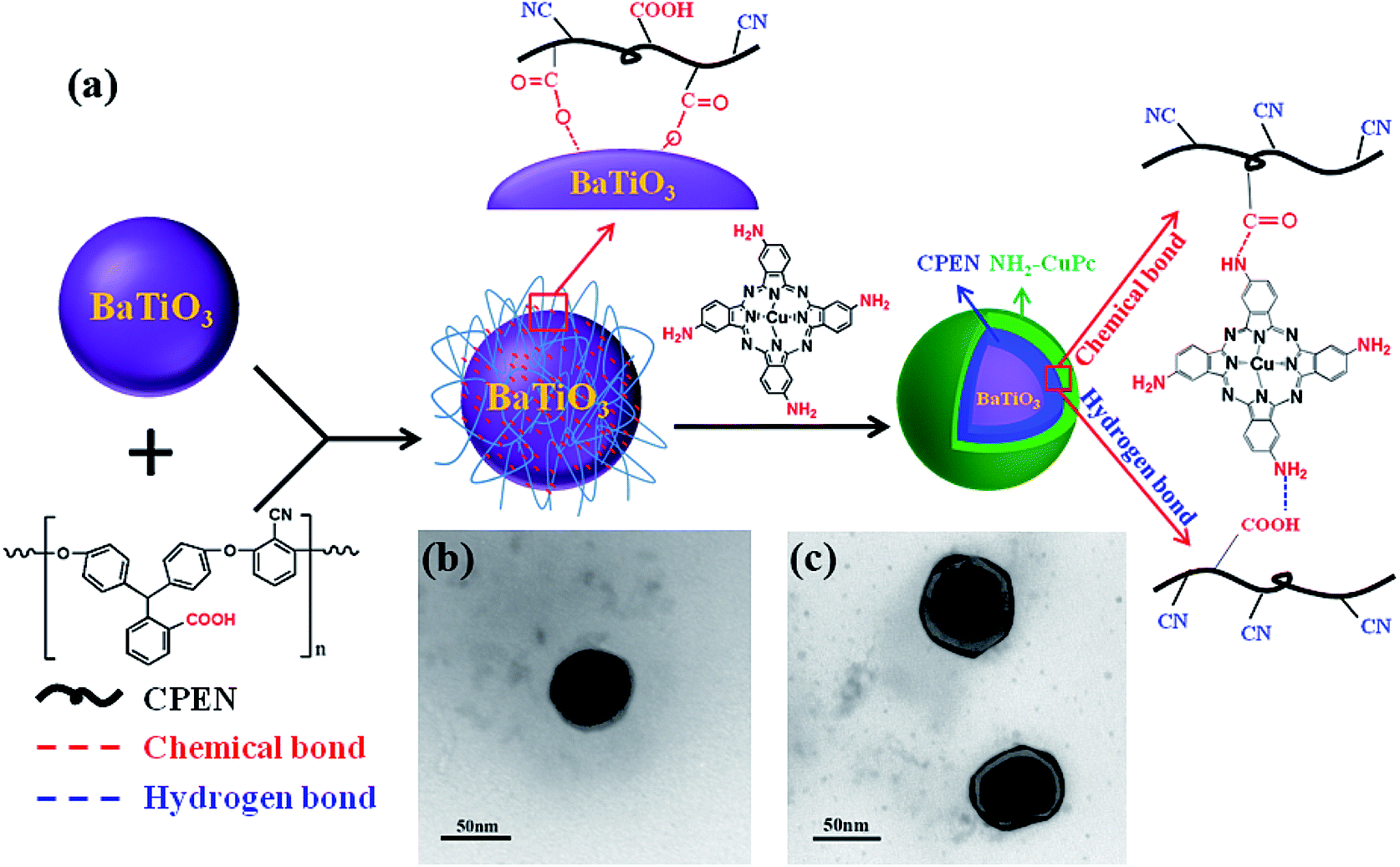 | ||
| Fig. 1 The preparation and characterization of the nanoparticles: (a) route of preparation; (b) and (c) TEM images of CPEN-f-BT and CPEN-f-BT@CuPc, respectively. | ||
Preparation of the CPEN-f-BT@CuPc/PEN films
CPEN-f-BT@CuPc/PEN multicomponent nanocomposite films were obtained via a solution casting method according to a previous report.22 CPEN-f-BT@CuPc/PEN nanocomposites (0 wt%, 2.0 wt%, 5.0 wt%, 10.0 wt%, and 20.0 wt%) were homogeneously suspended in NMP by stirring and ultrasonicating for 2 h. Then, the mixture was cast on a clean horizontal glass plate and then dried in an oven at 80, 100, 120, 160, and 200 °C (1 h each) to completely remove the solvent. After naturally cooling down to room temperature, the composite films with a thickness of about 60 µm were obtained.Characterization
Transmission electron microscopy (TEM) images were obtained using a JEM-2100F electron microscope with an accelerating voltage of 200 kV. Scanning electron microscopy (SEM) and energy dispersive spectrometry (EDS) were carried out using a JEOL JSM-5900LV at 20 kV. SEM samples were fractured in liquid nitrogen and then sputtered with gold on the fractured surface. X-ray photoelectron spectroscopic (XPS) measurements were carried out via an ESCA 2000 (VG Microtech, UK) using a monochromic Al Kα (hν = 1486.6 eV) X-ray source. Fourier transform infrared (FTIR) measurements were carried out via a Shimadzu 8400S FTIR spectrophotometer by incorporating the samples in the KBr pellets. Ultraviolet-visible (UV-vis) absorption spectra were obtained using a TU1800 ultraviolet-visible spectrophotometer (Beijing Purkinje General Instrument Co., Ltd). X-ray diffraction (XRD) analysis was carried out using a Rigaku RINT2400 X-ray diffractometer with Cu Kα radiation. The dielectric properties of the samples were tested using a TH 2819A precision LCR meter (Tong hui Electronic Co., Ltd.). The electric breakdown strength was tested by a Dielectric Withstand Voltage Tester (ZJC-50 kV).Differential scanning calorimetry (DSC) analysis was conducted using a TA Instruments DSC Q100 (NewCastle, DE, USA) modulated thermal analyzer. To eliminate the residual thermal history, two scanning cycles of heating and cooling were performed for each sample in the temperature range from 50 to 300 °C at a heating rate of 10 °C min−1 under a nitrogen atmosphere. The second heating scan was used to determine the Tg of the corresponding samples. Thermal gravimetric analysis (TGA) was carried out using a TA Q50 system under a nitrogen atmosphere at a heating rate of 20 °C min−1. Mechanical properties of the samples were tested using a SANS CMT6104 series desktop electromechanical universal testing machine (Shenzhen, China).
3. Results and discussions
The TEM observations are the intuitionistic characterization of the surface of BaTiO3 with CPEN and CPEN-f-BT functionalized with CuPc. As shown in Fig. 1b and c, it can be intuitively seen that the polymer layer is coated on the surface of BaTiO3 (Fig. 1b), and the outermost black layer belongs to CuPc (Fig. 1c), which has been successfully grafted onto the surface of CPEN-f-BT.As shown in Fig. 2a, it can be clearly seen that the UV-vis curve of CPEN-f-BT@CuPc has two strong absorption bands (Q-band: 600–700 nm and B-band: 300–400 nm) in both the visible and ultraviolet regions as compared to that of CPEN-f-BT, which is attributed to the π–π* transition from the phthalocyanine rings and the B-band absorption of the phthalocyanine ring.30 Wide-angle X-ray (WAXD) was further employed to confirm the surface of CPEN-f-BT functionalized with CuPc, as shown in Fig. 2b. Compared to the pattern of BaTiO3, all the peaks of BaTiO3 are reserved and three extra obvious diffraction peaks at 14.2°, 24.6°, and 28.9° can be observed in the pattern of CPEN-f-BT@CuPc, which are the main peaks of CuPc. All these results clearly reveal that CuPc coexists with the CPEN-f-BT nanoparticles. Fig. 2c is the SEM image that shows the uniform CPEN-f-BT@CuPc core–shell nanoparticles. Moreover, the surface chemical composition of the CPEN-f-BT@CuPc core–shell nanoparticles was further determined by EDS measurements, as described in Fig. 2d. The EDS pattern of the nanoparticle demonstrates that the CPEN-f-BT@CuPc core–shell nanoparticles are mainly composed of barium (Ba), titanium (Ti), oxygen (O), carbon (C), nitrogen (N), and copper (Cu) elements, which proves the existence of BaTiO3 and CuPc. The XPS provides essential and useful information about the chemical bond energy, which represents different kinds of chemical bonds, of a particular element. As shown in Fig. S2,† the full scanned XPS spectrum demonstrated the existence of barium (Ba), titanium (Ti), oxygen (O), carbon (C), nitrogen (N), and copper (Cu) elements in the CPEN-f-BT@CuPc core–shell nanoparticles. The N1s spectrum of CPEN-f-BT@CuPc could be quantitatively differentiated into the nitrogen species of C–N (398.13 eV), C![[triple bond, length as m-dash]](https://www.rsc.org/images/entities/char_e002.gif) N (398.33 eV), –NH2 (399.35 eV), –CONH (399.88 eV), and C
N (398.33 eV), –NH2 (399.35 eV), –CONH (399.88 eV), and C![[double bond, length as m-dash]](https://www.rsc.org/images/entities/char_e001.gif) N (400.54 eV) (Fig. 2e).31,32 The nitrogen species of C–N and CN originated from the phthalocyanine ring, and CN originated from the cyano groups on CPEN. –NH2 belongs to the amino group on NH2-CuPc, which is not involved in the chemical reaction. The peak at 399.88 eV is attributed to the amide bonds,31 which are formed by the reaction between –COOH from CPEN and –NH2 from NH2-CuPc in the system. The FTIR spectra of CPEN-f-BT and CPEN-f-BT@CuPc are shown in Fig. 2f. The absorption band at 2230 cm−1 corresponds to the symmetrical stretching vibration of the nitrile groups (–CN),10 and the characteristic band at 1245 cm−1 belongs to aryl ether.33 Moreover, the strong band at 567 cm−1 originated from the Ti–O vibration.34 Furthermore, the characteristic absorption peaks at 1097 cm−1, 1120 cm−1, and 1605 cm−1 in the spectrum of CPEN-f-BT@CuPc belong to the phthalocyanine ring, and the weak band at 3184 cm−1 corresponds to the characteristic absorption of the –NH stretching vibrations. Moreover, the enlarged FTIR spectrum from 1200 to 2000 wavenumber is shown in Fig. S3.† Small peaks at 1640, 1540, and 1320 cm−1 can be observed in this enlarged FTIR spectrum, which also confirm the formation of amide bonds. The low intensity of these peaks might result from the low content of the amide bonds.
N (400.54 eV) (Fig. 2e).31,32 The nitrogen species of C–N and CN originated from the phthalocyanine ring, and CN originated from the cyano groups on CPEN. –NH2 belongs to the amino group on NH2-CuPc, which is not involved in the chemical reaction. The peak at 399.88 eV is attributed to the amide bonds,31 which are formed by the reaction between –COOH from CPEN and –NH2 from NH2-CuPc in the system. The FTIR spectra of CPEN-f-BT and CPEN-f-BT@CuPc are shown in Fig. 2f. The absorption band at 2230 cm−1 corresponds to the symmetrical stretching vibration of the nitrile groups (–CN),10 and the characteristic band at 1245 cm−1 belongs to aryl ether.33 Moreover, the strong band at 567 cm−1 originated from the Ti–O vibration.34 Furthermore, the characteristic absorption peaks at 1097 cm−1, 1120 cm−1, and 1605 cm−1 in the spectrum of CPEN-f-BT@CuPc belong to the phthalocyanine ring, and the weak band at 3184 cm−1 corresponds to the characteristic absorption of the –NH stretching vibrations. Moreover, the enlarged FTIR spectrum from 1200 to 2000 wavenumber is shown in Fig. S3.† Small peaks at 1640, 1540, and 1320 cm−1 can be observed in this enlarged FTIR spectrum, which also confirm the formation of amide bonds. The low intensity of these peaks might result from the low content of the amide bonds.
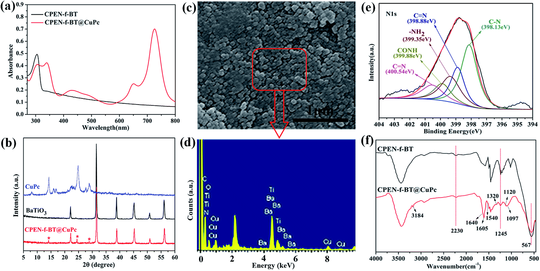 | ||
| Fig. 2 The characterization of nanoparticles: (a) UV-vis spectrum; (b) XRD patterns; (c) SEM image; (d) EDS patterns; (e) XPS N1s core-level spectrum; and (f) FTIR spectrum. | ||
In addition, the thermal and mechanical properties of the PEN-based nanocomposites are shown in Fig. 3. It can be seen that the glass transition temperatures Tg of the nanocomposites with different contents of CPEN-f-BT@CuPc are around 217 °C (Fig. 3a). The TGA curves of the nanocomposites are shown in Fig. S4;† all samples show excellent thermal resistance with an initial decomposition temperature (T5%) of over 527 °C in a N2 atmosphere. Fig. 3b shows the tensile strength and tensile modulus of the nanocomposites. The tensile strength and modulus of samples increase from 116.5 and 1943 MPa to 121.4 and 2192 MPa, respectively, when the content of nanofillers increases from 0 to 2.0 wt%. As more nanofillers are incorporated, the tensile strength and modulus of nanocomposite films decrease with the increasing content of nanofillers. This results from the fact that a large number of CPEN-f-BT@CuPc tend to agglomerate, which decreases the tensile strength of the nanocomposites. The corresponding cross-sectional micromorphology of the composite films is shown in Fig. S5.† However, the tensile strength and modulus are higher than 80 MPa and 1600 MPa, respectively, even when the content of nanofillers increases to 20.0 wt%.
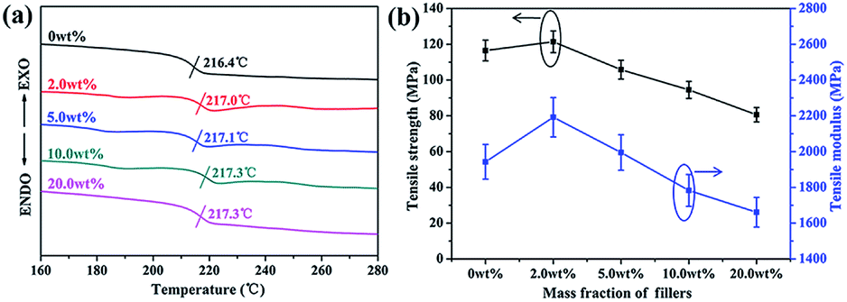 | ||
| Fig. 3 DSC curves (a) and mechanical properties (b) of the CPEN-f-BT@CuPc/PEN composite films. | ||
In addition, the elongation at break of all the samples is over 11.6% (as shown in Fig. S6†), meaning that these materials can be used as flexible dielectric materials. These results indicate that the nanocomposites show excellent mechanical and thermal properties.
Furthermore, the dielectric permittivity and loss tangent of the nanocomposites were measured as a function of frequency ranging from 100 Hz to 200 kHz at room temperature. As shown in Fig. 4a, the dielectric constant of all the nanocomposite films shows a weak decrement with the increasing frequency, which indicates that the samples have good permittivity–frequency stability. The dielectric constant of the PEN-based films increases from 3.9 to 9.0 at 1 kHz with the content of CPEN-f-BT@CuPc increasing from 0% to 20.0 wt%. This is because the polymer-based nanocomposite can form micro-capacitor networks, which has been reported elsewhere.35
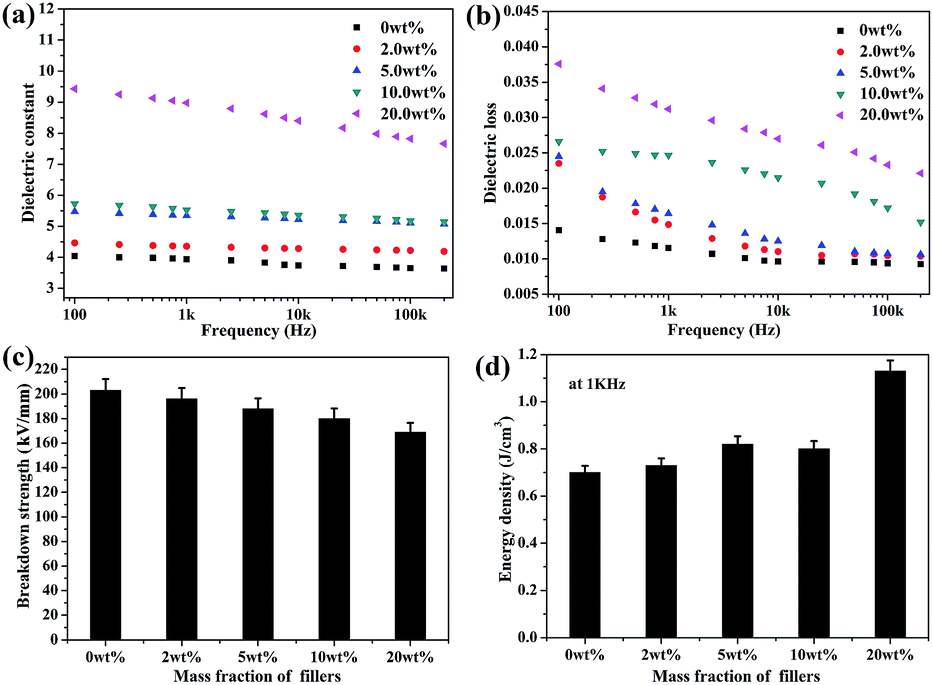 | ||
| Fig. 4 The dielectric properties (a), dielectric loss (b), breakdown strength (c), and energy density at 1 kHz (d) of the CPEN-f-BT@CuPc/PEN composite films. | ||
Furthermore, the number of micro-capacitors increases with the increasing content of the nanofillers, which improves the dielectric constant of the CPEN-f-BT@CuPc/PEN composite films. Compared to that of the BaTiO3/PEN composite films, the dielectric constant of the CPEN-f-BT@CuPc/PEN composite films is much higher at the same content of the nanofillers.36 This is mainly due to the fact that the surface-functionalized BaTiO3 nanoparticles have good compatibility with the polymer matrix, which provides better dispersion in the nanocomposite films (as shown in Fig. S5†). Moreover, the phthalocyanine ring and strong polar nitrile groups on the surface of BaTiO3 can also increase the electric charge. In addition, good compatibility of the nanoparticles within the polymer matrix also contributes to low loss tangent. As can be seen from Fig. 4b, the dielectric loss of the nanocomposite films at 1 kHz increases from 0.0115 to 0.0312 when the nanofillers content increases. The breakdown strength of the nanocomposite films was tested at room temperature, and the results are shown in Fig. 4c. It can be seen that the breakdown strength of the samples decreases from 202.8 to 168.6 kV mm−1 as the nanofillers content increases. The energy density was calculated from eqn (1) and the results are presented in Fig. 4d. The energy density (U) of a capacitor is given by the following equation:
 | (1) |
The temperature-dependence of the dielectric properties of the nanocomposite films was further investigated. The dielectric constant and dielectric loss of the composite film (20.0 wt%) were measured as a function of temperature from 25 °C to 250 °C at 1 kHz, and the results are shown in Fig. 5a. It is clear that the dielectric properties are relatively stable with respect to temperature before Tg and abruptly increase when the temperature is higher than the Tg of PEN. It is because the macromolecular motion is restricted when the temperature is below the Tg of PEN. However, when the temperature is higher than the Tg of PEN, the macromolecular motion and polarization inside the polymer are enhanced.37 In addition, the dielectric constant remains almost the same at different temperatures with the increasing frequency (Fig. 5b). These results indicate that the samples have good permittivity–frequency stability even at 160 °C. Furthermore, the breakdown strength of the sample at different temperatures presents a slight decrease lower than that at 160 °C, as shown in Fig. 5c. Therefore, the calculated results indicate that the energy density at different temperatures present a stable trend (Fig. 5d), which also confirm the permittivity–temperature stability of the composite films.
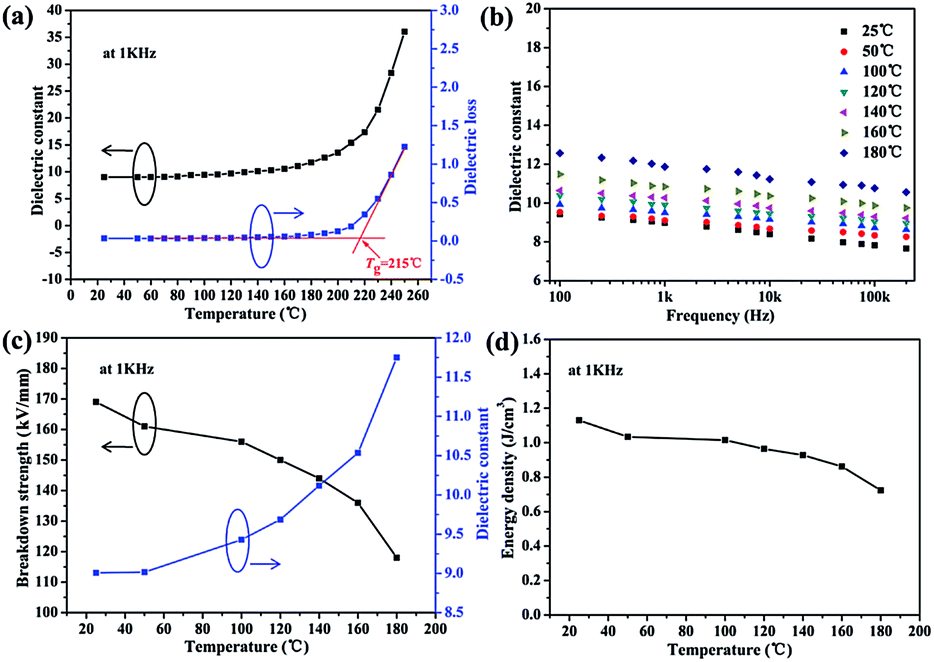 | ||
| Fig. 5 The energy storage characteristics of the CPEN-f-BT@CuPc/PEN composite films: (a), (c), and (d) the dielectric constant, breakdown strength, and energy density at 1 kHz, respectively. (b) The dielectric constant at different temperatures. | ||
4. Conclusions
In summary, novel core–shell-structured CPEN-f-BT@CuPc nanoparticles were successfully prepared by grafting CuPc onto BaTiO3 whose surface was modified by CPEN. Then, the CPEN-f-BT@CuPc/PEN composites films were prepared through a solution casting method combined with an ultrasonic dispersion technology. The results showed that the dielectric constant of the composites at 1 kHz was enhanced from 3.9 to 9.0 and the energy density of the composites increased from 0.70 to 1.13 J cm−3 when the content of the nanofillers increased from 0% to 20.0 wt%, respectively. Furthermore, a stable dielectric constant and energy density were observed for these films in the temperature range of 25–160 °C, which indicates great potential of these nanocomposites for use as organic film capacitors.Acknowledgements
The financial support from National Natural Science Foundation of China (Project No. 51603029 and 51373028) and UESTC (Project No. A03013023601012) are gratefully acknowledged.Notes and references
- B. J. Chu, X. Zhou and K. L. Ren, et al., Science, 2006, 313, 334–336 CrossRef CAS PubMed
.
- A. Imhof and D. J. Pine, Nature, 1997, 389, 948–951 CrossRef CAS
- Z. M. Dang, J. K. Yuan and S. H. Yao, et al., Adv. Mater., 2013, 25, 6334–6365 CrossRef CAS PubMed
- J. Li, S. I. Seok and B. Chu, et al., Adv. Mater., 2009, 21, 217–221 CrossRef CAS
- Y. Shen, Y. Lin and Q. M. Zhang, MRS Bull., 2015, 40, 433–458 CrossRef
- J. N. Coleman, U. Khan and Y. K. Gun'ko, Adv. Mater., 2006, 18, 689–706 CrossRef CAS
- J. Yang, H. L. Tang and Y. Q. Zhan, et al., Mater. Lett., 2012, 72, 42–45 CrossRef CAS
- Y. You, R. B. Wei and R. Q. Yang, et al., RSC Adv., 2016, 6, 70877–70883 RSC
- R. B. Wei, K. Li and J. Y. Ma, et al., J. Mater. Sci. Mater. Electron., 2016, 27, 9565–9571 CrossRef CAS
- Z. J. Pu, L. F. Tong and M. N. Feng, et al., RSC Adv., 2015, 5, 72028–72036 RSC
- J. Yang, X. L. Yang and Z. J. Pu, et al., Mater. Lett., 2013, 93, 199–202 CrossRef CAS
- W. Yang, X. L. Yang and Z. J. Pu, et al., J. Appl. Polym. Sci., 2014, 131, 40100–40107 Search PubMed
- V. K. Thakur and R. K. Gupta, Chem. Rev., 2016, 116, 4260–4317 CrossRef PubMed
- D. Padalia, G. Bisht and U. C. Johri, et al., Solid State Sci., 2013, 19, 122–129 CrossRef CAS
- X. Zhang, Y. Ma and C. Zhao, et al., Appl. Surf. Sci., 2014, 305, 531–538 CrossRef CAS
- L. Xie, X. Huang and C. Wu, et al., J. Mater. Chem., 2011, 21, 5897–5906 RSC
- T. Hoshina, J. Ceram. Soc. Jpn., 2013, 121, 156–161 CrossRef CAS
- C. W. Beier, M. A. Cuevas and R. L. Brutchey, Langmuir, 2010, 26, 5067–5071 CrossRef CAS PubMed
- X. Huang, M. N. Feng and X. B. Liu, J. Mater. Sci.: Mater. Electron., 2014, 25, 97–102 CrossRef CAS
- L. Xie, X. Huang, Y. Huang, K. Yang and P. Jiang, J. Phys. Chem. C, 2013, 117, 22525–22537 CAS
- R. X. Wang, Q. Zhu and W. S. Wang, et al., New J. Chem., 2015, 39, 4407–4413 RSC
- X. Huang, M. N. Feng and X. B. Liu, RSC Adv., 2014, 4, 4985–4992 RSC
- K. Yang, X. Huang and Y. Huang, et al., Chem. Mater., 2013, 25, 2327–2338 CrossRef CAS
- H. Liu, Y. Shen and Y. Song, et al., Adv. Mater., 2011, 23, 5104–5108 CrossRef CAS PubMed
- K. Yu, Y. Niu and Y. Zhou, et al., J. Am. Ceram. Soc., 2013, 96, 2519–2524 CrossRef CAS
- H. L. Tang, J. Yang and J. C. Zhong, et al., Mater. Lett., 2011, 65, 1703–1706 CrossRef CAS
- Y. You, X. Huang and Z. J. Pu, et al., J. Polym. Res., 2015, 22, 211–219 CrossRef
- B. Achar and K. J. Lokesh, Organomet. Chem., 2004, 689, 3357–3361 CrossRef CAS
- H. L. Tang, P. Wang and P. L. Zheng, et al., Compos. Sci. Technol., 2016, 123, 134–142 CrossRef CAS
- Z. C. Wang, W. Yang and J. J. Wei, et al., Mater. Lett., 2014, 123, 6–9 CrossRef CAS
- J. H. Zhu, Y. X. Li and Y. Chen, et al., Carbon, 2011, 49, 1900–1905 CrossRef CAS
- W. J. Gammon, O. Kraft and A. C. Reilly, et al., Carbon, 2003, 41, 1917–1923 CrossRef CAS
- Z. J. Pu, H. L. Tang and X. Huang, et al., Colloids Surf., A, 2012, 415, 125–133 CrossRef CAS
- C. Li, Y. Gu and X. B. Liu, et al., Thin Solid Films, 2006, 515, 1872–1876 CrossRef
- F. He, S. Lau and H. L. Chan, et al., Adv. Mater., 2009, 21, 710–715 CrossRef CAS
- H. L. Tang, J. C. Zhong and J. Yang, et al., J. Electron. Mater., 2011, 40, 141–148 CrossRef CAS
- R. Q. Yang, R. B. Wei and K. Li, et al., Sci. Rep., 2016, 6, 36434–36440 CrossRef CAS PubMed
Footnote |
| † Electronic supplementary information (ESI) available. See DOI: 10.1039/c7ra03549g |
| This journal is © The Royal Society of Chemistry 2017 |