 Open Access Article
Creative Commons Attribution 3.0 Unported Licence
Facile synthesis of uniform magnetic graphitic carbon for an efficient adsorption of pentachlorophenol†
Pengpeng Qiua,
Dingyun Cuib and
Jeehyeong Khim *a
*a
aDepartment of Civil, Environmental and Architectural Engineering, Korea University, Seoul 136-701, Republic of Korea. E-mail: hyeong@korea.ac.kr
bYeongdeok High School, 334 Meyong-ro, Yeongtong-gu, Suwon-si, Gyeonggi-do, Republic of Korea
First published on 12th July 2017
Abstract
Uniform core–shell structured magnetic graphitic carbon (Fe3O4@SiO2@g-C) nanospheres were fabricated via a two-step Stöber coating strategy, followed by a carbonization process in N2 atmosphere. The resultant composites possess a large magnetic susceptibility (25 emu g−1) and a high graphitization degree, making it an excellent magnetically separable adsorbent for the removal of pentachlorophenol.
Pentachlorophenol (PCP) is an important chlorinated aromatic organic compound that is widely used as a pesticide, a disinfectant, and a wood preservative. As a result, the concentration of PCP in the aquatic system is continuously increasing year by year. In addition, long-term exposure to PCP, even at very low level concentrations, can cause severe harmful effects on the liver, kidneys, lungs and nervous system of human beings.1 Therefore, the development of an efficient technology to treat PCP is necessary. Till now, commonly used strategies include biological degradation, membrane filtration, adsorption, and advanced oxidation technology.2 Among them, adsorption has been considered as one of the most practical and reliable technologies because of several advantages such as low cost, high efficiency, and simplicity in operation.3 Recently, graphitic carbon (g-C) – based materials are of vital importance in this field for their special structure, high rigidity and good chemical stability.4 However, they are very difficult to separate and regenerate during application, especially in a slurry operating system. To address this issue, magnetic separation provides a very convenient approach for removing and recycling magnetic particles such as magnetite, ferrite, and barium ferrite by applying external magnetic fields. It has been demonstrated that the incorporation of magnetic components into the adsorbent can greatly enhance the separation and recovery.5 To date, several methods (laser assisted irradiation,6 thermal plasma,7 microwave heating,8 chemical vapor condensation,9 and hydrothermal10) have been used for the synthesis of this type of material. However, most of these methods are associated with some disadvantages such as involving relatively harsh reaction conditions, requiring high energy cost, producing materials with aggregated structures, etc. Therefore, to develop a facile method to synthesize uniform magnetic g-C with a high adsorption performance for PCP is very much desired.
Herein, uniform core–shell structured magnetic g-C nanospheres (Fe3O4@SiO2@g-C) have been fabricated via a two-step Stöber coating method, followed by a carbonization process. The introduction of a rigid silica layer between Fe3O4 core and graphitic carbon shell is to help prevent leaching of Fe3O4, as well as increase the thermal stability of the resultant core–shell material during the carbonization process. After treated at 850 °C in N2 gas, the magnetic g-C possesses a well-defined core–shell structure with a large magnetic susceptibility (25 emu g−1) and a high graphitization degree. Finally, the magnetic g-C is used as an adsorbent, showing an excellent adsorption capacity for PCP. Moreover, the adsorbent can be easily recycled within 30 s by using an external magnetic field and the constant adsorption ability is retained even after 5 cycles.
The synthesis strategy for the core–shell structured magnetic g-C nanospheres is depicted in Fig. 1. First, the uniform magnetite particles were coated with a nonporous silica layer through a general Stöber coating approach in the presence of tetraethyl orthosilicate (TEOS) (denoted as Fe3O4@SiO2). Then, a layer of resorcinol–formaldehyde (RF) resin was deposited onto the silica layer through interface polymerization of resorcinol and formaldehyde catalyzed by ammonium hydroxide due to the strong electrostatic attraction between resorcinol derivatives and NH4+ absorbed on Fe3O4@SiO2 (defined as Fe3O4@SiO2@RF).11 Finally, the resultant composites were carbonized in N2 at 850 °C (designated as Fe3O4@SiO2@g-C).
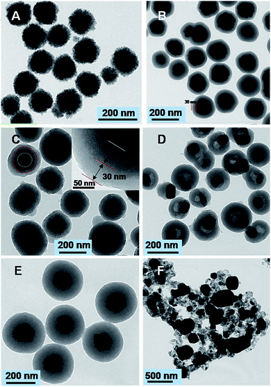
The obtained Fe3O4 particles possess a uniform spherical shape with an average diameter of ∼130 nm (Fig. 2A). The particles exhibit excellent dispersibility in polar solvents such as water and ethanol because of numerous citrate groups anchored on the surface, facilitating the subsequent coating. The Fe3O4@SiO2 nanospheres after the first Stöber coating process shows a relatively smooth surface with a diameter of ∼190 nm (Fig. 2B). TEM images reveal that a silica layer with a thickness of ∼30 nm is uniformly coated onto the magnetic core, resulting in a well-defined core–shell structure. The further Stöber coating leads to the formation of sandwich-like Fe3O4@SiO2@RF nanospheres with an average diameter of 250 nm, indicating the presence of ∼30 nm thick carbon layer (Fig. 2C). Notably, when the core–shell Fe3O4@SiO2@RF samples after being carbonized at 850 °C in nitrogen, discrete and uniform nanospheres are well retained (Fig. 2D). However, the delocalization of Fe3O4 cores was observed, which is possibly resulted from the recrystallization of Fe3O4 but inhibited by the outer silica shell. The energy-dispersive X-ray (EDX) of the magnetic g-C (Fig. S1†) clearly showed the characteristic peaks of titanium, carbon, silica and oxygen, suggesting the possible coexistence of Fe3O4, SiO2, and carbon. In contrast, when carbonizing Fe3O4@RF sample at the same temperature without the silica layer coating (Fig. 2E), the well-defined core–shell structures were completely collapsed and the magnetite cores were gathered into a larger particle (Fig. 2F), indicating the importance of silica interlayer towards increasing the thermal stability of the resultant composites.
 | ||
| Fig. 2 TEM images of the Fe3O4 nanoparticles (A), Fe3O4@SiO2 core–shell nanostructures (B), Fe3O4@SiO2@RF (C), Fe3O4@SiO2@g-C (D), Fe3O4@RF (E), and Fe3O4@g-C (F) nanospheres. | ||
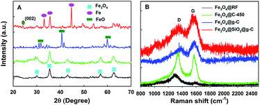
The XRD patterns (Fig. 3A) of the Fe3O4@RF and Fe3O4@C-450 (Fe3O4@RF sample carbonized at 450 °C) core–shell nanospheres display several broad characteristic diffraction peaks at 2θ = 30.1, 35.4, 43.1, 56.9, and 62.5°, which are typical for Fe3O4 crystalline phase (can be indexed as 220, 311, 400, 511, and 440, respectively). Compared with the pristine sample, diffraction peak attributed to the graphite (002) was also found in the XRD pattern of the Fe3O4@SiO2@g-C composites, suggesting that the RF was well carbonized into g-C.12 In addition, the iron peaks at 2θ = 44.6 and 49.4° were detected, which is possibly due to the inhibition effect of silica towards the crystallization of Fe3O4. The formation of iron in the composites could be attributed to the reducibility of carbon. Notably, this is good for the formation of magnetic g-C with a large magnetic property because iron (200 emu g−1) typically exhibits a larger magnetization than the magnetite (50–80 emu g−1).13 Unlike the Fe3O4@SiO2@g-C sample, the XRD pattern of the core–shell Fe3O4@g-C sample shows intense crystalline diffraction peaks at 2θ = 33.7 and 42.6°, in accordance with FeO crystals (diamagnetic), which gives a bad effect on the magnetic property of the resultant composites, further revealing the priority of coating a silica interlayer. To check the graphitic character of the resultant composites, the Raman spectra was recorded in the range of 500–2500 cm−1 (Fig. 3B). In the Raman spectra of the resultant composites, the appearance of two prominent peaks D (1368 cm−1) and G (1590 cm−1) are assigned to the disordered hybridized carbon atoms (A1g) and the stretching vibrations of sp2 bonds of perfect graphite crystals (E2g mode), respectively. It is widely believed that the intensity ratio of the D and G bands, ID/IG, is a measure of the crystallinity of carbon.14 The relatively small ID/IG ratio of magnetic g-C over other samples indicates the low density of the disordered sp2 – hybridized carbon atoms, suggesting a high graphitization degree of the magnetic g-C.
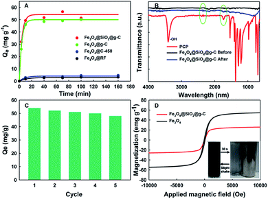
The performance of the resultant magnetic g-C composites for the adsorptive removal of PCP was evaluated at pH 6.8 (Fig. 4A). As a control, the adsorption performances of PCP in the presence of pristine Fe3O4@RF and Fe3O4@C-450 were also tested, exhibiting the adsorption capacity of 3.0 and 4.8 mg g−1, respectively. The comparable adsorption performance of these two materials was possibly attributed to the similar BET surface areas (Fig. S2†). Interestingly, when the magnetic g-C was used as an adsorbent, the adsorption capacity was sharply increased. It has been found that the absorption capacity of the magnetic g-C with silica coating is 55 mg g−1, which is larger than that of the magnetic g-C without silica coating (50 mg g−1), further revealing the importance of coating a silica interlayer. More importantly, this value is much higher than that of previous magnetic adsorbent developed for the removal of PCP (35–50 mg g−1, Table S1†).15 The BET surface area normalized adsorption capacity (2.30 mg m−2) is 3–5 times larger than that of magnetic biochar based adsorbent, indicating the magnetic g-C possesses more effective surface area. The excellent adsorption performance of magnetic g-C can be attributed to not only the relative large BET surface area (Fig. S1†) but also the π–π interaction between the PCP molecules and g-C, which was demonstrated by FTIR spectra (Fig. 4B). In the FTIR spectra, the peak at 3425 cm−1 is related to the hydroxyl group. However, in the spectra of Fe3O4@SiO2@g-C, this peak was not observed, indicating the surface of the magnetic g-C is full of C![[double bond, length as m-dash]](https://www.rsc.org/images/entities/char_e001.gif) C or C
C or C![[double bond, length as m-dash]](https://www.rsc.org/images/entities/char_e001.gif) O bond. The many characteristic peaks of PCP (e.g. 2300–2400 and 1700–1800 cm−1) were also detected on magnetic g-C after adsorption, indicating that PCP is adsorbed on the magnetic g-C. In addition, the C
O bond. The many characteristic peaks of PCP (e.g. 2300–2400 and 1700–1800 cm−1) were also detected on magnetic g-C after adsorption, indicating that PCP is adsorbed on the magnetic g-C. In addition, the C![[double bond, length as m-dash]](https://www.rsc.org/images/entities/char_e001.gif) C peak of magnetic g-C after adsorption shifts from ∼1524 to ∼1552 cm−1, which can be attributed to the π–π interactions between the benzene rings PCP and magnetic g-C.5c,16 In addition, this adsorbent can also be used to efficiently remove other aromatic emerging organic pollutants (Fig. S3†) such as bisphenol-A (BPA, 25 mg g−1) and rhodamine B (RhB, 59 mg g−1). However, the larger adsorption capacity of RhB than BPA could be attributed to that the former one possessed more π–π interaction forces resulted from the presence of more aromatic rings (Fig. S3B and C†).
C peak of magnetic g-C after adsorption shifts from ∼1524 to ∼1552 cm−1, which can be attributed to the π–π interactions between the benzene rings PCP and magnetic g-C.5c,16 In addition, this adsorbent can also be used to efficiently remove other aromatic emerging organic pollutants (Fig. S3†) such as bisphenol-A (BPA, 25 mg g−1) and rhodamine B (RhB, 59 mg g−1). However, the larger adsorption capacity of RhB than BPA could be attributed to that the former one possessed more π–π interaction forces resulted from the presence of more aromatic rings (Fig. S3B and C†).
The recycle adsorption test of the core–shell structured Fe3O4@SiO2@g-C was also examined (Fig. 4C). After five recycles, the adsorption performance of the recovered adsorbent was slightly reduced (12%), indicating the good reusability of this material. Notably, no ion ions were detected when leaving the magnetic g-C in acidic solution with a pH = 3, which is attributed to the protecting effect by the silica interlayer. However, the material cannot be worked in a strong alkaline solution because the silica interlayer could be etched by the alkali, affecting the longevity of the adsorbent.17 To investigate the magnetic capacity of the resultant composites, the magnetization (an indicator of the magnetic property) was measured. The magnetization saturation values of pristine Fe3O4 particles and Fe3O4@SiO2@g-C are detected to be ∼58.4 and 25.0 emu g−1, respectively (Fig. 4D). As a result of the superparamagnetic property and high magnetization, the core–shell Fe3O4@SiO2@g-C nanospheres in their homogeneous dispersion show fast motion under the applied magnetic field (become transparent within 30 s) and quick dispersibility upon a slight shake when the magnetic field is removed (Fig. 4D insert).
In summary, we report the synthesis of uniform core–shell structured magnetic g-C via a successive Stöber coating strategy, which is facile, mild and effective. The resultant Fe3O4@SiO2@g-C nanospheres possess well-defined core–shell structure with a large magnetic susceptibility (∼25.0 emu g−1), a relatively large BET surface area (25.7 m2 g−1), and a high graphitization degree. Then, it was demonstrated as an adsorbent for the removal of PCP, showing an excellent adsorption capacity (55 mg g−1), which is much higher than that of the previous magnetic adsorbent (35–50 mg g−1). In addition, it exhibits an excellent reusability (adsorption capacity remaining constant after 5 cycles) and fast magnetic separation capacity (magnetic separation time < 30 s). This study paves a great way to synthesize and design a magnetic adsorbent for efficiently removal of PCP.
Acknowledgements
We thank the Korea Mine Reclamation Corporation (MIRECO, Q1512631) for the financial support.Notes and references
- (a) J. P. DiVincenzo and D. L. Sparks, Environ. Sci. Technol., 1997, 31, 977–983 CrossRef CAS; (b) Research watch: pentachlorophenol exposure, Environ. Sci. Technol., 1998, 32, 511A Search PubMed; (c) K. Kim, P. Qiu, M. Cui and J. Khim, Chem. Eng. J., 2016, 284, 1165–1173 CrossRef CAS.
- (a) O. Rubilar, G. Feijoo, C. Diez, T. A. Lu-Chau, M. T. Moreira and J. M. Lema, Ind. Eng. Chem. Res., 2007, 46, 6744–6751 CrossRef CAS; (b) J. Lin, Y. He, J. Xu, Z. Chen and P. C. Brookes, J. Agric. Food Chem., 2014, 62, 9974–9981 CrossRef CAS PubMed; (c) C. Visvanathan, L. N. Thu, V. Jegatheesan and J. Anotai, Desalination, 2005, 183, 455–464 CrossRef CAS; (d) F. J. Benítez, J. L. Acero, A. I. Leal and F. J. Real, J. Hazard. Mater., 2008, 152, 373–380 CrossRef PubMed; (e) I. Oller, S. Malato and J. A. Sánchez-Pérez, Sci. Total Environ., 2011, 409, 4141–4166 CrossRef CAS PubMed.
- (a) A. J. Slaney and R. Bhamidimarri, Water Sci. Technol., 1998, 38, 227–235 CrossRef CAS; (b) X. Xue, K. Hanna, M. Abdelmoula and N. Deng, Appl. Catal., B, 2009, 89, 432–440 CrossRef CAS.
- (a) J. Liu, T. Zhang, Z. Wang, G. Dawson and W. Chen, J. Mater. Chem., 2011, 21, 14398–14401 RSC; (b) K. Yang and B. Xing, Chem. Rev., 2010, 110, 5989–6008 CrossRef CAS PubMed.
- (a) L. Sun, C. Tian, L. Wang, J. Zou, G. Mu and H. Fu, J. Mater. Chem., 2011, 21, 7232–7239 RSC; (b) H. Niu, Y. Wang, X. Zhang, Z. Meng and Y. Cai, ACS Appl. Mater. Interfaces, 2012, 4, 286–295 CrossRef CAS PubMed; (c) Z. Jin, X. Wang, Y. Sun, Y. Ai and X. Wang, Environ. Sci. Technol., 2015, 49, 9168–9175 CrossRef CAS PubMed; (d) P. Qiu, W. Li, B. Thokchom, B. Park, M. Cui, D. Zhao and J. Khim, J. Mater. Chem. A, 2015, 3, 6492–6500 RSC.
- J. B. Park, S. H. Jeong, M. S. Jeong, J. Y. Kim and B. K. Cho, Carbon, 2008, 46, 1369–1377 CrossRef CAS.
- J. H. Byeon and J.-W. Kim, ACS Appl. Mater. Interfaces, 2010, 2, 947–951 CAS.
- M. Bystrzejewski, Z. Karoly, J. Szepvolgyi, W. Kaszuwara, A. Huczko and H. Lange, Carbon, 2009, 47, 2040–2048 CrossRef CAS.
- D. S. Jacob, I. Genish, L. Klein and A. Gedanken, J. Phys. Chem. B, 2006, 110, 17711–17714 CrossRef CAS PubMed.
- (a) S. H. Yu, X. J. Cui, L. L. Li, K. Li, B. Yu, M. Antonietti and H. Cölfen, Adv. Mater., 2004, 16, 1636–1640 CrossRef CAS; (b) X. Sun and Y. Li, Angew. Chem., Int. Ed., 2004, 43, 597–601 CrossRef PubMed.
- Q. Yue, J. Li, W. Luo, Y. Zhang, A. A. Elzatahry, X. Wang, C. Wang, W. Li, X. Cheng, A. Alghamdi, A. M. Abdullah, Y. Deng and D. Zhao, J. Am. Chem. Soc., 2015, 137, 13282–13289 CrossRef CAS PubMed.
- G. Sun, X. Li, Y. Qu, X. Wang, H. Yan and Y. Zhang, Mater. Lett., 2008, 62, 703–706 CrossRef CAS.
- (a) J. Crangle and G. M. Goodman, Math. Phys. Sci., 1971, 321, 477–491 CrossRef CAS; (b) Y. Liu, Y. Wang, S. Zhou, S. Lou, L. Yuan, T. Gao, X. Wu, X. Shi and K. Wang, ACS Appl. Mater. Interfaces, 2012, 4, 4913–4920 CrossRef CAS PubMed.
- (a) P. Qiu, B. Park, J. Choi, M. Cui, J. Kim and J. Khim, J. Alloys Compd., 2017, 70, 67–15 Search PubMed; (b) A. C. Ferrari, Solid State Commun., 2007, 14, 47–57 CrossRef.
- (a) P. Devi and A. K. Saroha, Bioresour. Technol., 2014, 169, 525–531 CrossRef CAS PubMed; (b) L. Zhou, S. Pan, X. Chen, Y. Zhao, B. Zou and M. Jin, Chem. Eng. J., 2014, 257, 10–19 CrossRef CAS; (c) P. Devi and A. K. Saroha, Chem. Eng. J., 2015, 271, 195–203 CrossRef CAS; (d) J. Yang, J.-Y. Li, J.-Q. Qiao, S.-H. Cui, H.-Z. Lian and H.-U. Chen, Appl. Surf. Sci., 2014, 32, 1126–1135 Search PubMed.
- L. Wang, C. Tian, G. Mu, L. Sun, H. Zhang and H. Fu, Mater. Res. Bull., 2012, 47, 646–654 CrossRef CAS.
- P. Qiu, K. Kang, K. Kim, W. Li, M. Cui and J. Khim, RSC Adv., 2015, 5, 96201–96204 RSC.
Footnote |
| † Electronic supplementary information (ESI) available. See DOI: 10.1039/c7ra03535g |
| This journal is © The Royal Society of Chemistry 2017 |


