 Open Access Article
A novel high-content CNT-reinforced SiC matrix composite-fiber by precursor infiltration and pyrolysis process
X. S. Zhang†
a,
L. W. Yang†b,
H. T. Liu *a and
M. Zua
aScience and Technology on Advanced Ceramic Fibers and Composites Laboratory, National University of Defense Technology, Changsha 410073, China. E-mail: htslht@163.com
bIMDEA Materials Institute, C/Eric Kandel 2, 28906 Getafe, Madrid, Spain
First published on 27th April 2017
Abstract
A novel carbon nanotube (CNT)-reinforced SiC matrix composite-fiber with excellent mechanical, electrical, and thermal resistant properties was fabricated by filling the macroscopic CNT fibers with a polycarbosilane precursor-derived SiC matrix at 1000 °C. The SiC matrix had a nanoporous and amorphous microstructure, uniformly distributed among the CNTs. The CNT experienced some compressive residual stresses due to the matrix shrinkage during processing, leading to densification of the fiber, increase in the hopping channel number, and strong CNT/SiC interfacial interaction. The composite fiber displayed a brittle-fracture response during tensile deformation, with the tensile modulus and strength ∼1.5 times higher those of pure fiber. The dominant fracture mechanism was a bridging effect of SiC on the CNTs that favored better load transfer during tensile deformation. Unlike that for the pure fiber, the mechanical performance of the composite fiber was well maintained after harsh treatment at 1000 °C in Ar, evidencing its excellent thermal resistant property. In addition, the electrical conductivity of the composite-fiber was ∼1 time higher than that of the pure fiber and 4–5 times higher than that of the PAN-based carbon fiber, mainly due to the denser fiber microstructure after SiC infiltration. Finally, the composite-fiber showed a better oxidation resistant property, demonstrating promising applicability under high temperature and oxidation conditions.
1. Introduction
Carbon nanotube (CNT) fibers have been the focus of significant research over the past decade due to their excellent mechanical, electrical, and thermal properties.1 They have shown great potentials in numerous applications such as multifunctional reinforcements, electronics, and electrochemical devices.1–10 Typical microstructure of the CNT fiber contains numerous pores, gaps, and defects between adjacent shells, nanotubes, and nanotube bundles, which are detrimental to the macro performances of the assembled fiber. Therefore, the mechanical and electrical properties of the CNT fiber are still far below those of single CNTs.4–6 One effective way to enhance the mechanical properties of the CNT fibers is to tailor their textures via twisting, liquid densification, mechanical densification, etc.7–12 However, the structures of pure fibers are vulnerable under high temperatures and oxidation environments. It has been reported that the oxidation of CNTs could be triggered at a temperature of ∼450 °C in air.13–15 In the non-oxidizing atmosphere (Ar), the strength and electrical conductivity of the pure CNT fiber could also be degraded by 30% and 40%, respectively, after 900 °C heat treatment,13 due to the evaporation or decomposition of the residuals in the CNT fibers.An alternative way to reinforce the CNT fibers is to fabricate the so-called composite-fiber via polymer infiltration.10,11,16,17 For example, compositing the CNT fibers with an epoxy resin would improve the tensile strength and modulus of the pure CNT fibers by ∼26% and ∼41%, respectively.16 The related strengthening mechanism is substitution of the weak van der Waals interaction into the strong cross-linked structure between CNTs. While the conductivity of the CNT fiber is hopping mechanism-controlled,18,19 the electrical performance of the CNT/polymer assembly is limited by the poor conductivity of the polymers, which could probably enhance the contact resistance among mutual CNTs.3 Since CNT fibers can be potentially applied as reinforcements in composite materials, especially in ceramic matrix composites (CMCs),20 the development of a thermal- and oxidation-resistant CNT-based fiber with enhanced mechanical and electrical properties is thus in urgent demand, considering the extreme service conditions of CMCs such as high temperatures (≥1000 °C), oxidation atmospheres, etc.
Compositing the CNT fibers with thermal resistant ceramics (such as SiC) is a possible but scarcely explored method. Compared to polymers, SiC is chemically inert and high-temperature tolerant.14,15,21–25 In addition, SiC is much stiffer and stronger and can bond the CNTs tighter than polymers to bridge the CNTs and CNT bundles.22,23,26–28 Finally, due to semi-conductive characteristics, SiC can reduce the contact resistance among CNTs to improve the electrical transportations.29–31 Chemical vapor infiltration (CVI) and precursor infiltration and pyrolysis (PIP) are the two main methods to fabricate the SiC matrix in CMCs.32 However, to date, these methods have rarely been employed in the fabrication of a novel composite-fiber with optimized properties of both the CNT fibers and SiC ceramics. In addition, the strengthening/toughening and electrical transportation mechanisms in the typical CNT-reinforced brittle ceramic composite-fiber system have also been rarely explored.
This study focuses on the development of a novel thermal and oxidation resistant CNT-reinforced brittle SiC ceramic matrix (CNT/SiC) composite-fiber system with simultaneously enhanced mechanical and electrical properties; moreover, this system can be potentially applied as multifunctional reinforcements under extreme conditions (high temperatures, oxidation environments, etc.). The structures of the fiber were characterized by combining scanning electron microscopy (SEM), transmission electron microscopy (TEM), X-ray photoelectron spectroscopy (XPS), and Raman spectroscopy. The mechanical properties were quantified by uniaxial tensile tests, and the strengthening/fracture mechanisms were identified based on the obtained stress–strain curves and the fracture surface observations. The temperature-resistant properties were studied by measuring the tensile properties of the fibers after 800 °C and 1000 °C heat treatment in an Ar atmosphere. The electrical and oxidation resistant properties of the CNT/SiC fibers were finally evaluated.
2. Experimental
2.1 Preparation of the CNT/SiC composite-fibers
The CNT fibers (SCNC-F400, produced in Suzhou Creative Nano Carbon Co., Ltd., China) were fabricated by a direct spinning method. The SiC was fabricated in the CNT fiber interiors by the PIP method using polycarbosilane (PCS) as the SiC precursor. The chemical structure of PCS is shown in Fig. 1a. Pyrolysis of PCS at 1000 °C can lead to the formation of amorphous SiC with an excess of ∼13.5 wt% free carbon (analyzed by C/S (EMIA 320, Horiba) and N/O (EMGA-620W, Horiba) analyzers). The schematic of the PIP process is illustrated in Fig. 1b. The as-received CNT fibers were first mounted on a graphite mold. A small tensile force was applied to make the fibers straight. Following this, the module was infiltrated in a PCS solution (10 wt% PCS + 90 wt% xylene; the viscosity was 5.5 mPa s) in vacuum for 4 hours to allow adequate solution penetration. After drying, the PCS-infiltrated CNT fibers were pyrolyzed at 1000 °C for 0.5 hour in Ar to fabricate the SiC matrix. The PIP process was finally repeated 6 times to optimize the density and minimize the porosity of the composite-fibers. Fig. 1c shows an as-fabricated CNT/SiC fiber hanging a 20 g weight, showing that its flexibility is as good as that of the pure CNT fiber.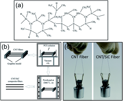 | ||
| Fig. 1 (a) The chemical structure of the PCS. (b) Schematic of the CNT/SiC fiber fabrication process. (c) The as-received CNT fiber and the as-fabricated CNT/SiC fiber hanging a 20 g weight. | ||
2.2 Characterizations
The morphologies and microstructures of the CNT and CNT/SiC fibers were characterized by SEM (Hitachi FEG S4800 and Helios 600i FEI), equipped with an energy dispersive spectrometer (EDS, Oxford INCA 350). Smooth cross-sections of the CNT and CNT/SiC fibers were fabricated using a three-ion-beam cutting instrument (Leica EM TIC 3X) to avoid surface contamination. X-ray photoelectron spectroscopy (Thermo ESCALAB 250Xi with Al Kα radiation) was employed to quantify that the phase compositions existed in the pure and the composite fibers. Raman spectroscopy was used to analyze the residual stress states in the fibers based on ref. 33–36. TEM (Talos F200X, FEI) was utilized to characterize the crystallographic structure of the CNT/SiC fibers. The TEM specimen was fabricated by Ga+ ion milling using a focused ion beam (FIB, Helios 600i, FEI) system.The uniaxial tensile tests were performed using a Testometric Micro 350 tensile tester to quantify the mechanical properties of the CNT and CNT/SiC fibers. Prior to the test, the fiber specimen with a gauge length of 10 mm was glued on a testing paper to ensure a straight loading direction along the fiber axis. Then, the specimen was tested under quasi-static tensile loading at the loading rate of 0.5 mm min−1. The average diameter of each specimen was calculated by averaging 10 measurements at different locations along the fiber axis in the gauge section using an optical microscope. The engineering stress and strain were calculated based on the obtained force and displacement data. A total of ten samples of each type of fiber were measured to ensure the validity of the obtained results.
The electrical resistances of the CNT and CNT/SiC fibers were measured using a Keithley 2000 multimeter. To achieve a better electrical contact, silver paste was used to fix the two ends of the tested fiber on a glass slide. The electrical conductivity was calculated based on Ohm's law. The thermal and oxidation resistant properties of the fibers were evaluated using a thermogravimetric (TG, Netzsch Model STA 449F3) system in Ar and air atmospheres, respectively, at the heating rate of 10 °C min−1 and the airflow rate of 40 mL min−1.
3. Results and discussion
3.1 Composite-fiber microstructures
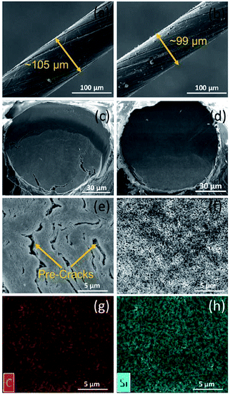
Fig. 2 shows the surface and cross-sectional morphologies of the CNT and CNT/SiC fibers. The as-received CNT fiber was ∼105 μm in diameter and displayed a twisted structure (Fig. 2a). After the SiC fabrication, the structure was retained, but the diameter was slightly reduced to ∼99 μm (Fig. 2b). The diameter reduction is probably attributed to the matrix shrinkage during the SiC fabrication, which could introduce some compressive residual stress into the fiber. Based on the cross-sectional images of the fibers (Fig. 2c and d), the linear density of the composite-fiber was 10.8 Tex, nearly twice that of the as-received CNT fiber (6.0 Tex). Note that long pre-cracks were distributed throughout the cross section of the pure CNT fiber, evidencing a loosely packed state of CNTs and a poor interaction between CNT bundles. However, after SiC infiltration, the pre-existing cracks were effectively healed, forming a homogeneous and uniform structure in the CNT/SiC fiber (Fig. 2d). Furthermore, the magnified image (Fig. 2f) demonstrated that the SiC matrix had a nanoporous structure, with the pore size <100 nm. EDS elemental mapping results reveal that the Si element was uniformly distributed in the cross-section of the composite-fiber; this indicates an adequate infiltration of SiC into the interior of the CNT fiber after the PIP process. The SiC volume fraction of the CNT/SiC fiber was 15–20%, calculated based on the linear densities of the CNT fiber and the CNT/SiC fiber (the density of SiC was 3.22 g cm−3, and the SiC weight fraction of the CNT/SiC fiber was 21–25%).Fig. 3a shows the survey XPS spectra of the as-received CNT fibers and the as-fabricated CNT/SiC fibers. The CNT fibers contained C and O elements. The existence of C element was mainly attributed to the C–C bonds in CNTs, whereas the O element might have originated from the hydroxyl and carboxyl groups existing in the fiber interiors or residual polymers and contaminations among CNTs during fiber fabrication. In comparison, the CNT/SiC fibers were composed of the extra Si element, evidenced by the two strong Si 2s and Si 2p peaks in the XPS spectra, in addition to the expected C and O elements. Detailed analysis of the Si 2p and C 1s peaks, as displayed in Fig. 3b and c, respectively, further indicates that the Si signals in the XPS spectra of the composite-fiber mainly originated from the SiC, SiCxOy, and SiO2 phases, which are the typical phase constituents of the SiC derived from the PCS pyrolysis.37–39
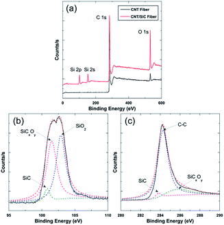 | ||
| Fig. 3 (a) The survey XPS spectra of CNT and CNT/SiC fibers. (b) The Si 2p peak in the spectra of the CNT/SiC fibers. (c) The C 1s peak in the spectra of the CNT/SiC fibers. | ||
Fig. 4 shows the TEM characterization of the as-fabricated CNT/SiC fiber. The CNTs had a multi-walled structure with a diameter of around 10 nm. They were preferentially aligned in the SiC matrix. Mutual CNTs were compactly inter-linked by the SiC matrix, and interfacial reaction was not observed. Due to the low pyrolysis temperature of PCS, the SiC matrix was mainly in an amorphous structure;37,38 therefore, it is difficult to individually address the amorphous SiC, SiCxOy, and SiO2 phases via TEM.
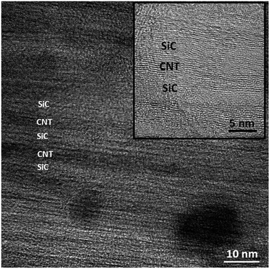 | ||
| Fig. 4 TEM microstructure of the CNT/SiC fiber. The inset is a magnified view of the SiC/CNT/SiC local zone. | ||
3.2 Residual stress characterization
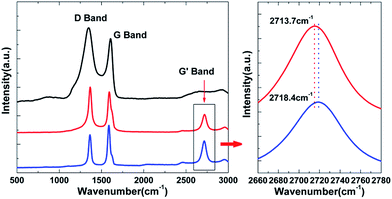
Generation of residual stress during the pyrolysis of the PCS at high temperatures is common in PIP-fabricated CMCs, which could have some impacts on the macro-mechanical performance and micro-interfacial properties.40 The residual stress in the as-fabricated CNT/SiC fiber was characterized via Raman spectroscopy. Fig. 5 shows the Raman spectrum of the CNT and CNT/SiC fibers. The data was acquired from the core regions of the cross-sections in both fibers. The Raman spectrum of the PCS-derived SiC is also presented for comparison, in which only the D and G bands of carbon were detected, and the peaks of the SiC matrix (at ∼790 and ∼970 cm−1) were missing. This is because the Raman scattering of carbon is at least 10 times higher than that of SiC.37,41 Although the PCS-derived SiC contains only ∼13.5 wt% free carbon, the scattering of these carbons still covers the signals of SiC. Therefore, in both the CNT and CNT/SiC fibers, where the CNT occupied a much higher volume/weight fraction, it is impossible to analyze the residual stress based on the information of the D and G bands. For this purpose, the G′ band was employed in this study because it is the characteristic band of the highly ordered carbon33 such as CNTs in both the CNT and CNT/SiC fibers. Moreover, this band was detected in the Raman spectrum of the two fibers, as shown in Fig. 5. The shift of the G′ band towards higher or lower wavenumber can be a hint to clarify whether the CNT is in compressive or tensile stress.34,35 The G′ band of the as-received CNT fiber was located at ∼2713.7 cm−1, which was shifted towards the right to ∼2718.4 cm−1; this indicates that after the SiC fabrication, the CNTs were in a compressive residual stress state, which was presumably mainly attributed to the matrix shrinkage during PCS pyrolysis.42This compressive residual stress that exists in the as-fabricated CNT/SiC fiber can help to explain the following observations: first, the diameter reduction of the CNT fiber after the SiC matrix fabrication, which could lead to the densification of the CNTs and increase in the number of hopping channels, and second, the reported strong CNT/SiC interface interaction,23 which is beneficial to the load transfer in the CNT/SiC/CNT networks. Accordingly, the mechanical and electrical performances of the composite-fiber were expected to enhance, as has been discussed in detail in the following section.
3.3 Mechanical properties
The mechanical properties of the as-received CNT fibers and the as-fabricated CNT/SiC fibers were quantified by uniaxial tensile tests. Fig. 6a shows the representative engineering stress–strain curves for both fibers. The CNT fibers displayed an elastic–plastic like response, with a negligible strain hardening effect that resulted in an elongation up to ∼15% strain. The measured tensile modulus was 7.2 ± 1.9 GPa, and the tensile stress was 279 ± 39.8 MPa. After SiC introduction, the CNT/SiC fibers exhibited an elastic-fracture deformation up to ∼5% strain, indicating a more brittle (due to the ceramic nature of SiC) but stronger mechanical response. Compared to those of the CNT fibers, both the elastic modulus and tensile strength of the CNT/SiC fibers dramatically increased to 17.9 ± 2.7 GPa and 713.8 ± 88.5 MPa, respectively. The nearly 1.5 times increase in the modulus and strength of the CNT fibers after the SiC fabrication indicate a high efficiency of the SiC ceramics, similar to that of other polymers (EP, PU, and PVA), to strengthen the CNT fibers.10,11,16 Note that the toughness of the CNT fiber after the SiC fabrication decreased from 23.6 ± 7.4 J g−1 to 14.9 ± 0.7 J g−1, calculated by integrating the stress–strain curves.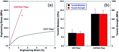 | ||
| Fig. 6 (a) Representative engineering stress–strain curves of the CNT and CNT/SiC fibers. (b) Comparisons of the tensile modulus and tensile strength of both fibers. | ||
The mechanisms of the strengthening of the CNT fibers by SiC could be as follows: first, CNT packing density in the CNT/SiC fibers becomes higher due to the matrix shrinkage effect; second, the effective healing of the pre-existing cracks occurs by SiC, thus leading to better load transfer in response to the external tensile stress; and finally, strong SiC/CNT interfacial strength is achieved.23 The mechanisms were further verified by the fracture surface observations of both fibers, as shown in Fig. 7. Due to the weak van der Waals interaction between the CNTs and CNT bundles, the as-received CNT fibers fractured mainly due to the mutual shearing of the CNTs and CNT bundles; this led to long pull-out of the CNTs and CNT bundles, with negligible strain hardening effect. In comparison, the CNT/SiC fibers displayed a much flat fracture surface with a short CNT pull-out, due to the bridging effect of SiC to the CNTs and the strong CNT/SiC interfacial interaction. Therefore, the fracture of the composite-fiber was mainly triggered by the brittle failure of the nano-porous SiC. Future work will be focussed on the optimization of the PIP process to fabricate a SiC matrix with lower porosity ratio and smaller porosity size to achieve even stronger CNT/SiC fibers.
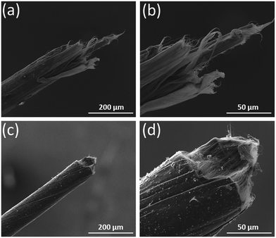 | ||
| Fig. 7 Fracture surfaces of (a and b) the CNT fiber and (c and d) CNT/SiC fiber after the uniaxial tensile test. | ||
3.4 Thermal resistant properties
It has been reported that for the pristine CNT fibers, high temperature exposure in non-oxidizing atmospheres would lead to the volatilization of the residual polymer and subsequently the loose CNT packing state, thus resulting in severe mechanical degradation of the fibers.13 This process could be effectively suppressed by the SiC infiltration into the fiber interiors. Fig. 8 shows the normalized weight retention ratio of the as-received CNT and the as-fabricated CNT/SiC fibers as a function of temperature in an Ar atmosphere. The introduction of the SiC matrix effectively impeded the mass loss of the fibers from ∼15% to ∼6% on elevating the temperature from 25 °C to 1000 °C. The lower mass loss of the composite-fiber implies a more stabilized fiber structure at high temperature, which should be mainly due to the protection of the CNT fiber structures by the thermally stable SiC ceramic. Therefore, the CNT/SiC fibers exhibit an enhanced thermal resistant property, compared to the pure fibers, as evidenced in Fig. 9. Uniaxial tensile tests were performed on the pure CNT and CNT/SiC fibers that were heat-treated at 800 °C and 1000 °C for 4 hours in an Ar atmosphere. The tensile strength retentions of the CNT/SiC fibers after 800 °C and 1000 °C heat treatment were ∼108% and ∼93%, respectively, which were ∼35% and ∼22% higher than those of the CNT fibers, respectively. The better thermal resistant property of the CNT/SiC fibers indicates a promising prospect of this novel fiber for high-temperature structural applications.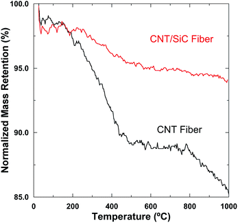 | ||
| Fig. 8 Normalized weight retention ratios of the CNT and CNT/SiC fibers as a function of temperature in an Ar atmosphere. | ||
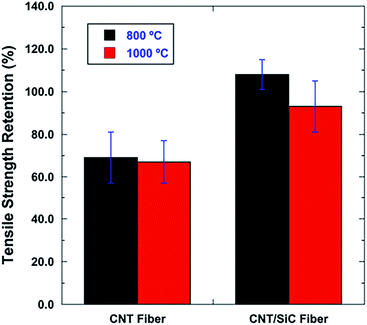 | ||
| Fig. 9 Tensile strength retentions of the CNT and CNT/SiC fibers after 800 °C and 1000 °C heat treatments in an Ar atmosphere. | ||
3.5 Electrical properties
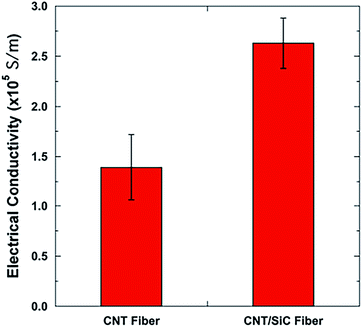
Generally, it is difficult to simultaneously enhance the mechanical and electrical properties of the CNT fibers by compositing them with polymers, functional nanoparticles, etc. For example, the introduction of polymers would enhance their mechanical property, but degrade the electrical property of the CNT fibers due to the insulating nature of the polymers;3,6 the introduction of electrical functional nanoparticles (Au, Pt, etc.) could enhance the electrical property of the CNT fibers, but at the expense of strength degradation due to the induced defects in the assembly structure.43 Fig. 10 shows the electrical conductivities of the CNT and CNT/SiC fibers. For the as-received CNT fibers, the electrical conductivity was ∼1.4 × 10⁵ S m−1, comparable to that of the typical CNT fibers reported in the literature and far smaller than that of the single CNT.3,41 After the introduction of the SiC matrix, the electrical conductivity of the CNT/SiC fibers increased to ∼2.6 × 10⁵ S m−1. The nearly 1 time increase in the electrical conductivity indicates an interesting positive effect of SiC on the electrical performance of the CNT fibers in addition to that on their mechanical performance. The dominant mechanisms in this electrical enhancement could be as follows: first, the reduction of the contact resistance between the CNTs and CNT bundles by the formation of CNT/semi-conductive SiC/CNT networks (the SiC matrix has excess free carbon with electrical conductivity of 100 to 101 S m−1)31 and second, the increasing CNT packing density that triggers more hopping channel formations within the fibers.18,19 Note that the electrical conductivity of the commercial PAN-based carbon fibers is usually in the order of 104 S m−1.4,18 Therefore, in this study, the CNT/SiC fibers possessing excellent conductivity are promising candidates for a broad range of electrical functional applications, especially those requiring high temperature.3.6 Oxidation-resistant properties
Pure CNT fibers are vulnerable when exposed to oxidizing atmospheres at moderate temperatures,13 whereas the oxidation-resistant ability of the fibers could be enhanced by the introduction of the SiC matrix, due to its good oxidation-resistant characteristics. To study their oxidation-resistant properties, both the CNT and CNT/SiC fibers were heat-treated in air, and the normalized weight retention ratios of the two fibers as a function of temperature are shown in Fig. 11. For the as-received CNT fibers, on elevating the temperature from 25 °C up to ∼450 °C, there was a gradual weight loss mainly due to the volatilization or decomposition of the residual polymers present on the CNT fibers. Further increase in the temperature would lead to massive CNT oxidations, which was evidenced by a sharp weight loss of the fibers at temperatures >450 °C, showing poor oxidation resistance at moderate temperatures. However, this property could be obviously enhanced by SiC infiltration into the CNT fiber interiors. For the as-fabricated CNT/SiC fibers, the critical temperature that triggered massive oxidation of the composite-fiber was ∼650 °C. The nearly 200 °C increase should be mainly attributed to the protection of the CNTs by SiC, delaying the air diffusion and CNT oxidations.14,15 Accordingly, compared to the pure CNT or CNT/polymer fibers, this novel CNT/SiC fiber is more advantageous to resist oxidation at temperatures up to 650 °C, demonstrating promising applicability under a high temperature and oxidation environment.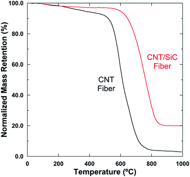 | ||
| Fig. 11 Normalized weight retention ratios of the CNT and CNT/SiC fibers as a function of temperature in an air atmosphere. | ||
4. Conclusions
In this study, a novel CNT-reinforced SiC matrix (CNT/SiC) composite-fiber with thermal and oxidation resistance was fabricated by cyclic precursor infiltration and a pyrolysis process using polycarbosilane as the matrix precursor. Compared to the pure CNT fiber, the CNT/SiC composite-fiber exhibited simultaneously enhanced mechanical, electrical, and thermal resistant properties. The following main conclusions can be drawn.(1) The CNT/SiC composite-fiber was denser and more uniform than the CNT fiber after the SiC matrix fabrication. The pore size in the SiC matrix was <100 nm, and the SiC matrix was mainly an amorphous structure, containing amorphous SiC, SiCxOy, and crystallized SiO2 nanoparticles. The CNT/SiC interface was compact, and chemical reactions were not observed. Residual compressive stress was generated in the as-fabricated CNT/SiC fiber, due to the matrix shrinkage during processing. This could probably lead to the densification of the structure, the increase in the hopping channel number and the enhancement in the CNT/SiC interfacial interaction.
(2) The composite-fiber displayed a brittle-fracture tensile response, with the tensile modulus and strength ∼1.5 times higher than that of the as-received CNT fiber. This indicates an obviously enhanced mechanical property of the CNT fiber by compositing the SiC ceramics. The dominant mechanism was a bridging effect of SiC on the CNT bundles that favored better load transfer in response to the tensile stress. Compared to the pure CNT fibers, harsh treatment at 1000 °C in Ar for 4 hours did not obviously degrade the mechanical properties of the as-fabricated composite-fiber, evidencing an excellent thermal resistant property of the CNT fiber composited with the SiC matrix.
(3) The electrical conductivity of the composite-fiber was ∼1 time higher than that of the as-received CNT fiber, mainly due to the denser microstructure of the composite-fiber. This indicates an interesting positive effect of the SiC ceramics on the electrical properties of the CNT fibers in addition to that on their mechanical properties. The oxidation-resistant property of the composite-fiber was also enhanced, due to protection by the oxidation-resistant SiC that delayed the air diffusion and CNT oxidation.
Acknowledgements
The authors thank the support of the National Natural Science Foundation of China (51402358). LWY acknowledges the financial support received from the China Scholarship Council (201306110007).Notes and references
- W. B. Lu, M. Zu, J. H. Byun, B. S. Kim and T. W. Chou, Adv. Mater., 2012, 24, 1805–1833 CrossRef CAS PubMed.
- A. S. Wu and T. W. Chou, Mater. Today, 2012, 15, 302–310 CrossRef CAS.
- A. Lekawa-Raus, J. Patmore, L. Kurzepa, J. Bulmer and K. Koziol, Adv. Funct. Mater., 2014, 24, 3661–3682 CrossRef CAS.
- J. N. Wang, X. G. Luo, T. Wu and Y. Chen, Nat. Commun., 2014, 5, 4848 CrossRef PubMed.
- L. Dumee, K. Sears, S. Mudie, N. Kirby, C. Skourtis and J. Mcdonnell, et al., Carbon, 2013, 63, 562–566 CrossRef CAS.
- X. Liu, Q. S. Yang, X. Q. He and K. M. Liew, Carbon, 2016, 106, 188–194 CrossRef CAS.
- K. Liu, Y. Sun, X. Lin, R. Zhou, J. Wang, S. Fan and K. Jiang, ACS Nano, 2010, 4, 5827–5834 CrossRef CAS PubMed.
- G. Hou, G. Wang, Y. Deng, J. Zhang, J. P. Nshimiyimana, X. N. Chi, X. Hu, W. G. Chu, H. W. Dong, Z. Zhang, L. Q. Liu and L. F. Sun, RSC Adv., 2016, 6, 97012–97017 RSC.
- Y. Sugimoto, M. Shioya, H. Matsumoto, M. Minagawa and A. Tanioka, Carbon, 2013, 60, 193–201 CrossRef CAS.
- A. Rahy, A. Choudhury, C. Kim, S. Ryu, J. Hwang, S. H. Hong and D. J. Yang, RSC Adv., 2014, 4, 43235–43240 RSC.
- S. Li, X. H. Zhang, J. N. Zhao, F. C. Meng, G. Xu, Z. Z. Yong, J. J. Jia, Z. G. Zhang and Q. W. Li, Compos. Sci. Technol., 2012, 72, 1402–1407 CrossRef CAS.
- S. Ryu, Y. Lee, J. W. Hwang, S. Hong, C. Kim, T. G. Park, H. Lee and S. H. Hong, Adv. Mater., 2011, 23, 1971–1975 CrossRef CAS PubMed.
- Z. B. Yang, X. M. Sun, X. L. Chen, Z. Z. Yong, G. Xu, R. X. He, Z. H. An, Q. W. Li and H. S. Peng, J. Mater. Chem., 2011, 21, 13772–13775 RSC.
- M. Luo, Y. Li, S. Jin, S. Sang and L. Zhao, Ceram. Int., 2011, 37, 3055–3062 CrossRef CAS.
- H. Mei, Q. L. Bai, K. G. Dassios, T. M. Ji, S. S. Xiao, H. Q. Li, L. F. Cheng and C. Galiotis, Ceram. Int., 2015, 41, 12495–12498 CrossRef CAS.
- M. Zu, W. Lu, Q. W. Li, Y. Zhu, G. Wang and T. W. Chou, ACS Nano, 2012, 6, 4288–4297 CrossRef CAS PubMed.
- H. U. Lee, C. H. Parkb and J. Y. Park, RSC Adv., 2016, 6, 2149–2154 RSC.
- Q. W. Li, Y. Li, X. F. Zhang, S. B. Chikkannanavar, Y. H. Zhao, A. M. Dangelewicz, L. X. Zheng, S. K. Doorn, Q. X. Jia, D. E. Peterson, P. N. Arendt and Y. T. Zhu, Adv. Mater., 2007, 19, 3358–3363 CrossRef CAS.
- W. H. Guo, C. Liu, F. Y. Zhao, X. M. Sun, Z. B. Yang, T. Chen, X. L. Chen, L. B. Qiu, X. H. Hu and H. S. Peng, Adv. Mater., 2012, 24, 5379–5384 CrossRef CAS PubMed.
- H. Peng, M. Jain, D. E. Peterson, Y. Zhu and Q. Jia, Small, 2008, 4, 1964–1967 CrossRef CAS PubMed.
- R. Ma, J. Wu, B. Wei, J. Liang and D. Wu, J. Mater. Sci., 1998, 3, 5243–5246 CrossRef.
- Y. Wang, Z. Iqbal and S. Mitra, Rapid, Carbon, 2006, 44, 2804–2808 CrossRef CAS.
- J. Hu, S. Dong, Q. Feng, M. Zhou, X. Wang and Y. Cheng, Carbon, 2014, 69, 621–625 CrossRef CAS.
- B. Román-Manso, S. M. Vega-Díaz, A. Morelos-Gómez, M. Terrones, P. Miranzo and M. Belmonte, Carbon, 2014, 80, 120–126 CrossRef.
- L. W. Yang, X. S. Zhang, H. T. Liu and M. Zu, Composites, Part B, 2017, 119, 10–17 CrossRef CAS.
- F. Deng, W. Lu, H. Zhao, Y. Zhu, B. S. Kim and T. W. Chou, Carbon, 2011, 49, 1752–1757 CrossRef CAS.
- Y. N. Liu, M. Li, Y. Gu, X. H. Zhang, J. N. Zhao and Q. W. Li, Carbon, 2012, 52, 550–558 CrossRef.
- Y. Z. Cai, L. Q. Chen, H. J. Yang, J. H. Gou, L. F. Cheng, X. W. Yin and H. F. Yin, Ceram. Int., 2016, 42, 4984–4992 CrossRef CAS.
- H. Liu, H. Cheng, J. Wang and G. Tang, J. Alloys Compd., 2010, 491, 248–251 CrossRef CAS.
- S. Xie, G. Q. Jin, S. Meng, Y. W. Wang, Y. Qin and X. Y. Guo, J. Alloys Compd., 2012, 520, 295–300 CrossRef CAS.
- F. Dalcanale, J. Grossenbacher, G. Blugan, M. R. Gullo, J. Brugger, H. Tevaearai, T. Graule and J. Kuebler, J. Eur. Ceram. Soc., 2015, 35, 2215–2224 CrossRef CAS.
- W. Krenkel, Ceramic matrix composites, WILEY-VCH Verlag GmbH & Co. KGaA, Weinheim, 2008 Search PubMed.
- M. A. Montes-Morán and R. J. Young, Carbon, 2002, 40, 857–875 CrossRef.
- T. Kobayashi, K. Sumiya, Y. Fukuba, M. Fujie, T. Takahagi and K. Tashiro, Carbon, 2011, 491646–491652 Search PubMed.
- N. Melanitis, P. L. Tetlow, C. Galiotis and S. B. Smith, J. Mater. Sci., 1994, 29, 786–799 CrossRef CAS.
- Y. Gao, J. Li, L. Liu, W. Ma, W. Zhou, S. Xie and Z. Zhang, Adv. Funct. Mater., 2010, 20, 3797–3803 CrossRef CAS.
- H. Liu, H. Cheng, J. Wang, G. Tang, R. Che and Q. Ma, Mater. Sci. Eng., A, 2009, 525, 121–127 CrossRef.
- P. Colombo, R. Riedel, G. D. Sorarù and H. J. Kleebe, Polymer derived ceramics, DEStech Publications, Lancaster, 2009 Search PubMed.
- S. Baunack, S. Oswald, H. K. Tönshoff, F. von Alvensleben and T. Temme, Fresenius. J. Anal. Chem., 1999, 365, 173–177 CrossRef CAS.
- H. T. Liu, L. W. Yang, S. Han, H. F. Cheng, W. G. Mao and J. M. Molina-Aldareguía, J. Eur. Ceram. Soc., 2017, 37, 883–890 CrossRef CAS.
- Y. Sasaki, Y. Nishina, M. Sato and K. Okamura, J. Mater. Sci., 1987, 22, 443–448 CrossRef CAS.
- J. Yang, R. Downes, A. Schrand, J. G. Park, R. Liang and C. Xu, Scr. Mater., 2016, 124, 21–25 CrossRef CAS.
- J. N. Zhao, Q. S. Li, B. Gao, X. H. Wang, J. Y. Zou, S. Cong, X. H. Zhang, Z. J. Pan and Q. W. Li, Carbon, 2016, 101, 114–119 CrossRef CAS.
Footnote |
| † These authors contribute equally to the work. |
| This journal is © The Royal Society of Chemistry 2017 |

